technetix AIMA3000.ASMM Operational manual

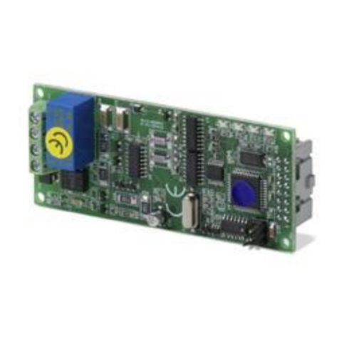
AIMA3000.ASMM
SYSTEM
MANAGEMENT
MODULE
Online
Email: customer.service.[email protected]
Website: technetix.com
Aug/2017 - V1
Technetix Group Limited
Product User Manual

Aug/2017 - V1
Product User Manual
AIMA3000.ASMM
Technetix Group Limited
Contents
1 About This Manual ....................................................................................................................................................5
1.1 Related Documentation........................................................................................................................................................................5
1.2 Technical Support...................................................................................................................................................................................5
2 Precautions.................................................................................................................................................................7
3 Overview.....................................................................................................................................................................8
3.1 About the Product ..................................................................................................................................................................................8
3.2 Features.....................................................................................................................................................................................................8
3.3 Specifications...........................................................................................................................................................................................9
3.4 Order Details............................................................................................................................................................................................9
4 Module Characteristics ............................................................................................................................................10
4.1 Block Diagram .........................................................................................................................................................................................10
4.2 Module Appearance..............................................................................................................................................................................11
4.2.1 Overview ..........................................................................................................................................................................................11
4.2.2 Front Panel View............................................................................................................................................................................12
4.2.3 Rear Panel View.............................................................................................................................................................................13
5 Installation ..................................................................................................................................................................14
5.1 Equipment Inventory..............................................................................................................................................................................14
5.2 Packing and Transportation.................................................................................................................................................................14
5.3 Power and Cooling Requirements....................................................................................................................................................14
5.4 Module Installation and Adjustment .................................................................................................................................................15
5.5 Module Removal .....................................................................................................................................................................................16
5.6 ASMM Connections ...............................................................................................................................................................................17
5.7 ASMM First Time Configuration .........................................................................................................................................................18
6 Technical Description ...............................................................................................................................................21
6.1 Overview ...................................................................................................................................................................................................21
6.2 Physical Description...............................................................................................................................................................................21
6.3 SNMP Agent.............................................................................................................................................................................................21
6.4 Management Software..........................................................................................................................................................................21

Aug/2017 - V1
Product User Manual
AIMA3000.ASMM
Technetix Group Limited
6.4.1 NMS3 Enterprise II.........................................................................................................................................................................21
6.4.2 Third Party Management Software ..........................................................................................................................................21
7 Module Control Parameters ...................................................................................................................................21
7.1 System Tab ...............................................................................................................................................................................................22
7.1.1 System Information .......................................................................................................................................................................24
7.1.2 Network Configuration.................................................................................................................................................................24
7.1.3 SNMP Configuration .....................................................................................................................................................................25
7.1.4 TFTP Server.....................................................................................................................................................................................26
7.1.5 Syslog Server..................................................................................................................................................................................27
7.1.6 User Management.........................................................................................................................................................................28
7.1.7 Date and Time................................................................................................................................................................................29
7.1.8 Factory Defaults .............................................................................................................................................................................30
7.1.9 Backup and Restore .....................................................................................................................................................................31
7.1.10 Reboot...............................................................................................................................................................................................32
7.2 Modules Tab.............................................................................................................................................................................................33
7.2.1 ASMM Module ................................................................................................................................................................................34
7.2.2 Other Modules................................................................................................................................................................................34
7.3 Alarms Tab ................................................................................................................................................................................................35
7.3.1 ASMM Alarms..................................................................................................................................................................................35
7.3.2 Other Module Alarms ...................................................................................................................................................................36
7.4 Logs Tab ....................................................................................................................................................................................................36
7.5 Upgrade Tab ............................................................................................................................................................................................37
7.5.1 Upgrading the ASMM...................................................................................................................................................................38
7.5.2 Upgrading Other Modules..........................................................................................................................................................38
8 LED Status Indicators ...............................................................................................................................................39
9 Status Parameter List and Alarm Limits................................................................................................................41
10 Declaration of Conformity .......................................................................................................................................42
Appendix A: dB Conversion Table.................................................................................................................................43

1Aug/2017 - V1 Technetix Group Limited
Product User Manual
AIMA3000.ASMM
1 About This Manual
1.1 Related Documentation
Documents listed below can be used in association with this Manual:
• Technetix.AIMA3000 - Product User Manual
• Technetix.AIMA ASMM - Product User Manual
• AIMA3000 NMS Web Management System Product User Manual
- Technetix.NMS3-EPSM - Basic Inventory Management
- Technetix.NMS3-EPSM - Basic Alarm Management
- Technetix.NMS3-EPSM - Basic System Management
- Technetix.NMS3-EPSM - Basic Template Management
1.2 Technical Support
Please contact the technical support team at Technetix if you have any problems during ASMM Module installation
or maintenance.
Europe:
Technetix BV
Kazemat 5
NL-3905 NR Veenendaal
P.O. Box 385
NL-3900 AJ Veenendaal
The Netherlands
Phone: +31 318 58 59 59
Email: customer.service.[email protected]

2Aug/2017 - V1 Technetix Group Limited
Product User Manual
AIMA3000.ASMM
1 Precautions
WARNING!
This equipment is intended for indoor applications. To prevent fire or electrical shock, or
damage to the equipment, do not expose units to water or moisture.
■Ensure the module has adequate cooling ventilation.
■The product user manual should be read and understood before the units are used.
■DO NOT power up before the cover and the panels of the equipment are installed and the
enclosure is closed. Modules with USB ports require port covers when not connected.
Cleaning
Only use a damp cloth for cleaning the front panel. Use a soft dry cloth to clean the top of the unit.
DO NOT use any spray cleaners or chemicals of any kind.
Outage or overload requiring service and repairs
Unplug the unit and refer the servicing to Technetix qualified service personnel only.
Servicing and repairs
DO NOT attempt to service this unit yourself. Refer all servicing needs to Technetix qualified service
personnel only.

3Aug/2017 - V1 Technetix Group Limited
Product User Manual
AIMA3000.ASMM
3 Overview
3.1 About the Product
The AIMA3000 System Management Module (ASMM) is the system controller module for the Technetix latest generation
Advanced Intelligent Multi-services Access Platform - the AIMA3000.
The ASMM control module supervises all Application Modules (AMs), power supplies, and fan modules within the
AIMA3000 chassis. It also serves as a communications interface between all the modules and user interfaces.
The front panel of the ASMM provides status LEDs for indicating various operations and alarms. There is a single fast
Ethernet port on the front for local control and monitoring. There are two fast Ethernet ports on the rear of the module for
secondary local control and SNMP communications with Technetix NMSE network management software. In addition, all
modules can be controlled and monitored through a web browser.
3.2 Product Key Features
■Plug-and-play AIMA3000 platform module
■Hot-swappable
■Embedded web server
■SNMPv2c compatible
■Provides firmware and device management for all modules
■Alarm and log management
■Maintenance management
■Three fast Ethernet ports for communication with local PCs and Technetix NMSE management software
■Remote firmware upgrade and auto upload/download of configuration files through the ASMM's web interface
or using Technetix NMSE
■Bulk firmware upgrades through Technetix NMSE
■Battery back-up for maintaining the Real Time Clock (RTC)
■FCC, CE and RCM(1) compliant
(1) See Declaration of Conformity for current status.

4Aug/2017 - V1 Technetix Group Limited
Product User Manual
AIMA3000.ASMM
3.3 Specifications
Communications interface (front panel)
Alarms Front-panel LEDs; SNMP Traps
RST Module reset button
LOCAL RJ45 10/100BaseT Ethernet connector
CONSOLE Micro-USB Device Type B connector (used by Technetix support engineers)
USB USB Host Type A connector
Communications interface (rear panel)
Alarm relay contacts Common, N/C and N/O contacts, 0.5 A, 40 Vac or Vdc maximum
Ethernet Ports 0 and 1 RJ45 10/100BaseT Ethernet connectors
General
Power supply Powered via AIMA3000 backplane
Power consumption < 5.0 W
Operating temperature -5 °C ~ +55 °C
Operating humidity Up to 90% RH (non-condensing)
Storage temperature -25 °C ~ +70 °C
Storage humidity Up to 90% RH (non-condensing)
Dimensions (W*D*H) 24.6 * 410 * 152.5 mm
Weight 0.7 kg
Network management Technetix NMSE, SNMP, ASMM Web interface
Maximum number of SNMPv2c Trap Addresses 5
3.4 Order Details
A-ASMM-A System Management Module, version A

5Aug/2017 - V1 Technetix Group Limited
Product User Manual
AIMA3000.ASMM
4 Module Characteristics
4.1 Block Diagram

6Aug/2017 - V1 Technetix Group Limited
Product User Manual
AIMA3000.ASMM
4.2 Module Appearance
4.2.1 Overview
Front Panel
Rear Panel
Multi-pin Connector

7Aug/2017 - V1 Technetix Group Limited
Product User Manual
AIMA3000.ASMM
4.2.2 Front Panel View
6
7
8
Note:
(*)The reset button performs a hardware reset of the ASMM module.
Item Description
1 Hinged tab (plastic face used for removing and locking the module in place)
2 LED status indicators (see Section 6)
3 RST - module reset button*
4 Orange tab-retaining clip
5 LOCAL - RJ-45 10/100BaseT Ethernet connector
6 CONSOLE – Micro USB Device Type B connector (for Technetix support use only)
7 USB - Host Type A connector
8 Module retaining screw

8Aug/2017 - V1 Technetix Group Limited
Product User Manual
AIMA3000.ASMM
4.2.3 Rear Panel View
Item Description
1 Alarm Relay Contacts:
- COM (Common)
- NC (Normally Closed)
- NO (Normally Open)
2 NET MGMT (RJ-45 Ethernet Port 0)
3 NET MGMT (RJ-45 Ethernet Port 1)
4 LAN Activity LEDs (green):
On - Link established
Flashing - Link active
O - No link established

9Aug/2017 - V1 Technetix Group Limited
Product User Manual
AIMA3000.ASMM
5 Installation
5.1 Equipment Inventory
On receiving a new ASMM, carefully unpack and examine the contents for loss or damage that may have occurred during
shipping. Refer to the warranty if loss or damage has occurred. The ASMM should include the following:
5.2 Packing and Transportation
Keep all packing boxes and packaging of the ASMM for future transport.
Use only the original packaging of the ASMM when transporting. This packaging has been specifically designed to
protect the equipment.
5.3 Power and Cooling Requirements
The ASMM module is powered by the power supply module of the AIMA3000 chassis. The module can consume
up to 5 W.
The ASMM module and its corresponding AIMA3000 chassis should be located in an environment not exceeding a
temperature range from -5 ºC to +55 ºC with the AIMA3000 fans running. Should the temperature exceed the above
limits, the AIMA3000 should be relocated in the equipment rack where the ambient temperature is less than 55 ºC.
No. Description Qty
1 ASMM module 1
2 Product User Manual (CD) 1
3 Individual test sheet (Certificate of Performance) 1

10Aug/2017 - V1 Technetix Group Limited
Product User Manual
AIMA3000.ASMM
5.4 Module Installation and Adjustment
Initial Checks
Visually check that the pins on the module’s multi-pin connector (as seen in section 4.2.1) are not bent or damaged.
Examine the module casing for any obvious damage, and ensure no screws are missing or loose. Check that the module’s
identifying label is present on the side of the casing. Make a note of the module type, its serial number and MAC address.
Note:
The ASMM module should be the first module installed and must be fitted into slot 0 of the AIMA3000 chassis.
Installing the Module
1. Gently depress the orange retaining clip and release the hinged tab
Hinged tab AIMA Module
Orange retaining clip

11Aug/2017 - V1 Technetix Group Limited
Product User Manual
AIMA3000.ASMM
Module fastening screw
Direction of module
installation/removal
2. Hold the AIMA module casing upright, align it with the AIMA3000 slide rails for the correct slot, and insert the
module until it reaches the multi-pin connector.
DO NOT use excessive force when inserting the module, but ensure the RF connectors at the rear of the module
are securely connected with the chassis's RF connectors.
CAUTION!
The module MUST be installed correctly to ensure a proper connection of the module’s multi-pin
connector and the backplane.
Tip:
When inserting the module into the guide rails, vertically tilt the module slightly to check that the guides are properly
seated on the rails. The module is guided to the correct position using the large metal fastening screw on the lower
part of the front panel.
3. After the module is inserted, gently push the hinged tab until it snaps into the orange retaining clip. While pushing
down on the hinged tab, the AIMA module will mate with the power bus and will lock in into the chassis
CAUTION!
If force is required to insert a module, then it may not be correctly seated on the slide rails, or the
mounting screw may be misaligned.
4. When the module is fully seated within the chassis, on the bottom of the AIMA module, fasten the spring-
loaded mounting screw. Only use fingers to fasten the mounting screw. DO NOT use a screwdriver.

12Aug/2017 - V1 Technetix Group Limited
Product User Manual
AIMA3000.ASMM
5.5 Module Removal
1. Disconnect the cables from the front panel of the ASMM module.
2. Disconnect the Ethernet cables from the rear of the ASMM module.
3. Disconnect the alarm relay cable from the rear of the ASMM module.
4. Unscrew the module retaining screw until it releases.
5. Gently press down on the orange retaining clip to release the hinged tab.
6. Lift the hinged tab to remove the module from the multi-pin connector.
7. Carefully use the hinged tab to initially pull the module out of the chassis.
8. Gently grip the module and continue to remove the module from the chassis.
CAUTION!
To avoid damage, do not pull the module by only using the hinged tab. Whenever the module is removed or
inserted from the chassis, secure the hinged tab in the closed position behind the orange retaining clip.

13Aug/2017 - V1 Technetix Group Limited
Product User Manual
AIMA3000.ASMM
5.6 ASMM Connections
On the rear panel, connect the:
■RJ-45 Ethernet Port 0 to a local network switch for network management using Technetix NMSE or a third-party
management software.
■You can also connect the RJ-45 Ethernet Port 1 of the primary ASMM module to Port 0 on the rear panel of a
secondary/slave ASMM module in another AIMA3000 chassis to create a daisy chain. Although many ASMM modules
can be linked, it is recommended that no more than six be linked to a single master ASMM module within 100 metres.
When operating as a daisy chain, each ASMM's IP address needs to be manually set prior to connecting.
Note:
Alternatively, you can use a LAN cable from a local network switch to Port 0 on the rear panel of a second ASMM module,
to create a daisy chain. In this case, Port 1 on both ASMM modules is not used. See the AIMA3000 system diagram below.
On the front panel, you can connect a:
■LOCAL RJ-45 Ethernet Port to a laptop PC for detailed configuration tasks via a web page interface (login required).
The default IP address is 192.168.25.168.
■USB Host Type A connector to a Android device running in USB host mode for initial configuration tasks, such as
setting the AIMA3000’s IP, Net mask and Gateway addresses common to USB and RJ-45. When using the USB Host
Type A connector, the ASMM acts as a client.

14Aug/2017 - V1 Technetix Group Limited
Product User Manual
AIMA3000.ASMM
5.7 ASMM First Time Configuration
RJ-Establish network connectivity through the RJ-45 Ethernet Port 0 on the rear panel of the ASMM. Connect to a local
network switch for network management.
Configuration using a laptop PC
1. Manually configure your network interface card to have an IP address on the 192.168.25.x block with the subnet
mask of 255.255.255.0.
2. Connect an Ethernet cable between the ASMM’s front LOCAL RJ-45 Ethernet port and the laptop PC.
3. Use a web browser to open the AIMA3000 web configuration interface via the default IP address of
192.168.25.168
4. Enter the default Username (admin) and Password (Technetix) to log in to the AIMA3000 system configuration
web interface.
Default user name: admin
Default password: Technetix
If you manually change the ASMM's IP address and forget it, you can still connect to the backup IP address at 10.10.10.10.
The IP of the client PC must be set to 10.10.10.9 and the front RJ-45 Ethernet port should be used to access the web
interface. The Backup IP is only supported by hardware version HW_A04259_4 and firmware version FW_S08471 01.01.16
or higher.
Enter the default Username (admin) and Password (Technetix) and log in to the AIMA3000 system configuration web page.
Configuration using an Android device
The Android application may not be compatible with all Android devices. The app was developed by Technetix to be used in
conjunction with a Lenovo Ideapad A1 07 running Android 2.3.4 Gingerbread. Before installing the application, the installation
of unknown sources must be enabled by going to settings > security > and check the box next to Unknown Sources.
1. Install the application:
To obtain a copy of the Android application, please contact a Technetix sales representative.
2. Turn o Wi-Fi on the Android device.
3. Go to the Android Settings menu. In the Wireless and Network settings menu select More Settings. On some
newer Android devices, there will be dedicated tethering or hotspot menu and this step can be skipped.

15Aug/2017 - V1 Technetix Group Limited
Product User Manual
AIMA3000.ASMM
4. Select the tethering and portable hotspot.
5. Enable USB tethering.

16Aug/2017 - V1 Technetix Group Limited
Product User Manual
AIMA3000.ASMM
6. Connect the Android device to the USB port on the front of the ASMM using a USB 2.0 cable.
7. The word tethered will appear at the top on the notification bar on the Android device.
Note:
If the ASMM is restarted, the USB cable will need to be disconnected and reconnected after the ASMM has completed its
boot cycle.
8. Open the web browser on your Android device.
9. Type the default IP address your Android device assigns to clients in tethering mode. The Lenovo Ideapad
A1 07 running Android 2.3.4 Gingerbread assigns 192.168.42.1 by default. This address will vary between devices
and manufacturers.
10. The ASMM login page will pop up. Enter the login (default login: admin) and password (default password:
Technetix). Passwords are case sensitive.

17Aug/2017 - V1 Technetix Group Limited
Product User Manual
AIMA3000.ASMM
6 Technical Description
6.1 Overview
The ASMM is designed to provide a user-friendly provisioning and management system. It allows remote control,
monitoring and provisioning through the Simple Network Management Protocol (SNMP) and the ASMM’s web interface.
6.2 Physical Description
The front of the ASMM has three ports. The LOCAL port is a standard RJ-45 Ethernet port, the port labelled USB is used for
management through Android devices. The port labelled CONSOLE is unused. The front panel has five LED indicators and
a module reset button.
On the rear panel there are two RJ-45 Ethernet ports and alarm relay contacts.
Power and data are supplied to the rear of the module through a 24-pin connector, which mates with only slot 0 in the
AIMA3000 chassis. Data for slots 1-16 are also routed through slot 0.
6.3 SNMP Agent
The ASMM is compatible with SNMPv2c Agent servicing requests through management software. It supports full-featured
remote provisioning and monitoring of connected application modules with up to 5 trap addresses.
The SNMP Agent includes MIB Tables and is compatible with the SCTE standard, which allows third party software to
interact with the ASMM whether it is for monitoring or provisioning.
6.4 Management Software
6.4.1 NMS3 Enterprise II
The NMS3 Enterprise II management system enables the operator to configure all individual elements of the network,
with the network tree view for easy navigation and fault-finding. Parameters of the ASMM can be monitored and changed
via the web interface. Individual ONUs can be configured using the EPON-EMS interface included with the NMS3
Enterprise II package.
6.4.2 Third Party Management Software
Third Party Management Software for billing and/or provisioning can be integrated into the system and communicates with
the ASMM via SNMPv2c.
7 Module Control Parameters
The ASMM module is controlled via a web interface, by first entering the AIMA3000’s web server IP address in your
browser’s address bar. You must then log in to the server by entering your username and password in the pop-up dialogue
box that appears.
Table of contents
Popular Control Unit manuals by other brands

VIEWEG
VIEWEG DV-5625-U instruction manual
DeZurik
DeZurik APCO CDD-9000T user manual

Siemens
Siemens SINUMERIK 828D Turning Programming manual

Honeywell
Honeywell VP522A quick start guide
Hubbell
Hubbell GAI-TRONICS 379-003 E3 IP MRM manual
HYDAC FILTER SYSTEMS
HYDAC FILTER SYSTEMS CTM-EB 1000 Series Operating and maintenance instructions
