technetix AIMA-OPSW Operational manual

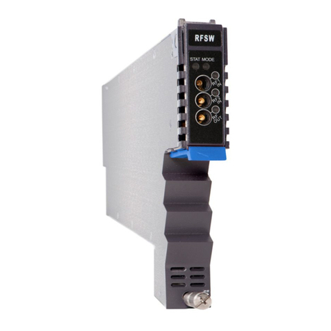
AIMA-OPSW
OPTICAL A/B
PROTECTION
SWITCH
Online
Email: customer.service.[email protected]
Website: technetix.com
Aug/2017 - V1
Technetix Group Limited
Product User Manual

Aug/2017 - V1
Product User Manual
AIMA-OPSW
Technetix Group Limited
Contents
1 Precautions.................................................................................................................................................................1
2 About This Manual ....................................................................................................................................................2
2.1 Chapter Overview ..................................................................................................................................................................................2
2.2 Related Documentation........................................................................................................................................................................2
2.3 Document Conventions........................................................................................................................................................................3
2.4 Technical Support...................................................................................................................................................................................3
3 Overview.....................................................................................................................................................................4
3.1 Product Description ...............................................................................................................................................................................4
3.2 Product Key Features............................................................................................................................................................................4
3.3 Specifications...........................................................................................................................................................................................10
3.4 Block Diagram .........................................................................................................................................................................................12
3.5 Order Details............................................................................................................................................................................................13
4 Module Characteristics ............................................................................................................................................15
4.1 Module Appearance and Port Layout..............................................................................................................................................15
4.1.1 Overview ..........................................................................................................................................................................................15
4.1.2 Front Panel Layout ........................................................................................................................................................................16
4.1.3 Rear Panel Layout..........................................................................................................................................................................18
4.2 Technical Description ............................................................................................................................................................................15
4.2.1 Block Diagram ................................................................................................................................................................................15
4.2.2 Technical Overview.......................................................................................................................................................................16
4.3 Functional Overview..............................................................................................................................................................................15
4.3.1 Optical Input Switching................................................................................................................................................................15
4.3.2 The Switched InputA Restore Function Introduction .........................................................................................................16
4.3.3 RF Input Level Measurement.....................................................................................................................................................18
5 Installation ..................................................................................................................................................................19
5.1 Preparatory Work for Installation .......................................................................................................................................................19
5.2 Installation Steps.....................................................................................................................................................................................19
5.3 Unpacking.................................................................................................................................................................................................20
5.4 Module Installation .................................................................................................................................................................................21

Aug/2017 - V1
Product User Manual
AIMA-OPSW
Technetix Group Limited
5.4.1 Connect the Optical Cables.......................................................................................................................................................21
5.4.2 Using the Sliding Fiber Guide....................................................................................................................................................23
5.4.3 Using the Fiber Tray......................................................................................................................................................................25
5.4.4 Cleaning the Fiber Connector Ends and the Front-panel Optical Ports......................................................................26
5.4.5 Connecting the Optical Fibers ..................................................................................................................................................26
5.5 Check Module's Power Supply ..........................................................................................................................................................26
5.6 Test the Optical Output Signal............................................................................................................................................................27
6 Module Configuration & Alarms .............................................................................................................................15
6.1 Login to the System Management Web Page...............................................................................................................................15
6.1.1 Configuration using a PC ............................................................................................................................................................15
6.1.2 Configuration using a Android device....................................................................................................................................16
6.2 Restore Factory Defaults......................................................................................................................................................................15
6.3 Reboot........................................................................................................................................................................................................15
6.4 Port Configuration...................................................................................................................................................................................15
6.4.1 Revert Function ..............................................................................................................................................................................16
6.5 Module Appearance and Port Layout..............................................................................................................................................15
6.5.1 Alarm Status Pages .......................................................................................................................................................................15
6.5.2 Module operating voltage and temperature alarm ............................................................................................................16
6.5.3 Module Port Alarms.......................................................................................................................................................................18
6.5.4 Alarm Monitoring Configuration................................................................................................................................................16
6.5.5 Temperature, +12V, +5V Voltage Alarms Levels Management .......................................................................................18
6.6 Input / Output Status Monitoring........................................................................................................................................................15
6.7 Logs Management..................................................................................................................................................................................15
6.8 Device Upgrade......................................................................................................................................................................................15
7 Troubleshooting.........................................................................................................................................................15
8 Product Warranty ......................................................................................................................................................15
9 Declaration of Conformity .......................................................................................................................................15
Appendix A: Default Alarm Limit Settings ...................................................................................................................15
Appendix B: dB Conversion Table.................................................................................................................................15

1Aug/2017 - V1 Technetix Group Limited
Product User Manual
AIMA-OPSW
1 Precautions
WARNING!
This equipment is intended for indoor applications. To prevent fire or electrical shock, or
damage to the equipment, do not expose units to water or moisture.
■You should carefully read and thoroughly understand the contents
of the manual before installing and using this equipment.
■A typical connector is the SC/APC 8°.
Note: An 8° angle polished optical connectors must be used.
■At any time, there may be dangerous voltage inside the device.
■Do not power up before the cover and the panels of the equipment
are installed and the enclosure is closed.
Cleaning
Only use a damp cloth for cleaning the front panel. Use a soft dry cloth to clean the top of the unit.
DO NOT use any spray cleaners or chemicals of any kind.
Outage or overload requiring service and repairs
Unplug the unit and refer only to Technetix's qualified service personnel.
Servicing and repairs
DO NOT attempt to service this unit yourself. Refer all servicing needs to Technetix's qualified service
personnel only.
WARNING!
Exposure to class 3A laser radiation is possible. Access should be restricted to
trained personnel only. Do not view exposed fibre or connector ends when handling
optical equipment.

2Aug/2017 - V1 Technetix Group Limited
Product User Manual
AIMA-OPSW
2 About This Manual
2.1 Chapter Overview
1. Precautions
2. About This Manual: Preface
3. Overview: Application module overview, including the module features, technical specifications, and
ordering information.
4. Module Characteristics: The appearance of the equipment, port, and introduction of other components
5. Installation: Installation procedure
6. Module Configuration & Alarms: Web management configuration instructions.
7. Troubleshooting
8. Product Warranty
9. Declaration of Conformity.
Appendix A: Default Alarm Parameters
Appendix B: dB Conversion Table
2.2 Related Documentation
The following documents may be used in conjunction with this manual:
- Technetix.AIMA3000 - Product User Manual
- Technetix.AIMA ASMM - Product User Manual
- AIMA3000 NMS Web Management System Product User Manual
- Technetix.NMS3-EPSM - Basic Inventory Management
- Technetix.NMS3-EPSM - Basic Alarm Management
- Technetix.NMS3-EPSM - Basic System Management
- Technetix.NMS3-EPSM - Basic Template Management

3Aug/2017 - V1 Technetix Group Limited
Product User Manual
AIMA-OPSW
2.3 Document Conventions
Before you use the manual, please familiarize yourself with the format used in this manual.
‘*’ Asterisk: Points marked with an asterisk means there are corresponding notes on the page
2.4 Technical Support
If you need help in the process of setting up and maintaining an FT5X, please contact Technetix’s technical
support sta:
Europe:
Technetix BV
Kazemat 5
NL-3905 NR Veenendaal
P.O. Box 385
NL-3900 AJ Veenendaal
The Netherlands
Phone: +31 318 58 59 59

4Aug/2017 - V1 Technetix Group Limited
Product User Manual
AIMA-OPSW
3 Overview
3.1 Product Description
The Optical A/B Protection Switch (OPSW) is designed to plug into Technetix's latest generation Advanced Intelligent Multi-
services Access platform - the AIMA3000.
The high isolation and impedance matched optical switch is microprocessor controlled and will operate in standalone
mode without the need of management software.
Switching is based on the measurement of optical and RF signals. These signals are compared to preconfigured minimum
and maximum thresholds parameters stored in the firmware tables.
Manual operation of the OPSW or the configuration of the optical and RF thresholds can be set through the web interface
using a computer, a mobile device, or through Technetix's NMSE management software.
3.2 Product Key Features
■Plug-and-play with the AIMA3000 platform
■Three adjustable optical input levels to suit dierent optical input ranges:
High: +10 dBm ~ +25 dBm (251.18 mW ~ 316.22 mW)
Middle: 0 dBm ~ +15 dBm (1 mW ~ 31.62 mW)
Low: - 10 dBm ~ + 5 dBm (0.1 mW ~ 3.16 mW)
■Fast switching time of 15 ms
■Non-Revert and Revert operating modes with user-adjustable delay
■Adjustable minimum thresholds of -10 dBm ~ +25 dBm on both inputs.
Operators can define the maximum and minimum parameters for automated switching
■Optical switching based on optical or RF power levels
■Comprehensive status monitoring through the built-in web interface
■Remotely upgradeable firmware and auto upload/download of configuration files
through ASMM web interface or use Technetix's NMSE
■Bulk firmware updates through Technetix's NMSE
■FCC, CE and RCM1compliant
1 See Declaration of Conformity for current status.

5Aug/2017 - V1 Technetix Group Limited
Product User Manual
AIMA-OPSW
3.3 Specifications
Optical Performance
Optical wavelength 1270 ~ 1630 nm
Optical input range -10 ~ +25 dBm
Insertion loss with connectors 2 dB maximum
Switch accuracy of optical < 0.5 dB
Optical crosstalk 55 dB maximum
Optical return loss 45 dB maximum
Optical connector type SC/APC, FC/APC, LC/APC, E2000/APC
(with optical safety shutter)
Alarms Front-panel LEDs, SNMP Traps
Switching time < 15 ms
RF Performance (Test port on the front panel)
RF power range10 ~ 30 dBmV/ ch, 77 ch NTSC
Switch accuracy of RF < 1 dB
RF Connectors 75 Ω Mini-SMB
General
Power supply1Powered via AIMA3000 backplane
Power consumption < 6.0 W
Operating temperature -5 ~ +55 °C
Operating humidity 90 % (Non-condensing)
Storage temperature -25 ~ 70 °C
Storage humidity 90 % (Non-condensing)
Dimensions (W x D x H) 24.6 mm x 402 mm x 152.5 mm
Weight 0.88 kg
Network management Technetix NMSE or through ASMM's Web interface
1 dBμV=60+dBmV

6Aug/2017 - V1 Technetix Group Limited
Product User Manual
AIMA-OPSW
3.4 Block Diagram
3.5 Order Details
A-OPSW-[Y]-[Z] Optical A/B Protection Switch
Options:
YOptical Connector Type
SSC/APC*
FFC/APC
LLC/APC
EE2000/APC
ZBandwidth
1G 45-1000 MHz
Figure 3 1 OPSW Block Diagram
*Standard option. Contact a PBN Sales Representative for availability of other options.

7Aug/2017 - V1 Technetix Group Limited
Product User Manual
AIMA-OPSW
4 Module Characteristics
4.1 Module Appearance and Port Layout
4.1.1 Overview
Front Panel
Rear Panel
Figure 4.1 Module Appearance

8Aug/2017 - V1 Technetix Group Limited
Product User Manual
AIMA-OPSW
4.1.2 Front Panel Layout
Figure 4-2 OPSW Front Panel Layout

9Aug/2017 - V1 Technetix Group Limited
Product User Manual
AIMA-OPSW
Table 4-1 OPSW Front Panel Functions
Item Number Item Description
1 MODE LED
Module Mode Indicator
AGC: Green
MGC: Green Light Blinking, once per second
2 STATUS LED
Module Status Indicator
Normal: Green
Minor Alarm: Orange
Major Alarm: Red
3 OPT1 LED
Input A status indicator (if choosing A, light blinks once per second)
ON: Green
Minor Alarm: Orange
Major Alarm: Red
4 OPT2 LED
Input B status indicator (if choosing B, light blinks once per second)
ON: Green
Minor Alarm: Orange
Major Alarm: Red
5 RF1/RF2 RF test ports of input A/input B
6 Orange tab-retaining clip Plug and anchor the module The tab-retaining clip will pop out
after pressing the orange release tab
7 OPT IN A Optical input A
8 OPT IN B Optical input B
9 OPT OUT Optical output
10 Mounting Screw Fasten OPSW Module
WARNING!
"OPT OUT" emits a non-visible laser radiation when working.

10Aug/2017 - V1 Technetix Group Limited
Product User Manual
AIMA-OPSW
Figure 4-3 OPSW Rear Panel Layout
4.1.3 Rear Panel Layout
Table 4-2 OPSW Rear Panel Functions
Item Number Item Description
1 Air vent Module air vent allowing air to flow out of the module
2 Multi-pin connector Power supply and communication port
3 Locating pin Used to position the module in the chassis

11Aug/2017 - V1 Technetix Group Limited
Product User Manual
AIMA-OPSW
4.2 Technical Decription
4.2.1 Block Diagram
Figure 4-4 OPSW Block Diagram
Parameters Glossary
OPT IN A also labeled InputB Optical input A
OPT IN B also labeled InputA Optical input B
OPT OUT Optical Output
RF TP A RF A test port
RF TP B RF B test port
PD Detect A/B
Amplifier Amplifier
ATT Adjustable attenuator
RF Detector Detect RF
TO BACK PLANE AND COMMS Data Bus
Table 4-3 OPSW Block Diagram Glossary

12Aug/2017 - V1 Technetix Group Limited
Product User Manual
AIMA-OPSW
4.2.2 Technical Overview
The OPSW switching module consists of three major parts. The first part is the optical input and output, which includes two
optical input ports: OPT IN A and OPT IN B, and one optical output port: OPT OUT. Two optical signal are separated from
this section by an optical divider, which is used to test the power of OPT IN A and OPT IN B.
The second part is signal testing, which includes two optical testing circuits and two RF testing circuits.
The last part is the microprocessor controller and monitor, which is used to perform monitoring functions and to select
which one of the two optical input signals is used. This microprocessor also communicates with the ASMM Inter-Integrated
Circuit (I2C) System. Users can manage the OPSW through the ASMM by using a tablet computer or PC (see the installation
section of this manual).
4.3 Functional Overview
4.3.1 Optical Input Switching
InputA of the OPSW switching module is the primary input. The isolation between Input A and Input B is more than 55
dB. Both inputs (Input A and B) signal levels are separated by an optical divider in the optical section, then go through
the optical testing circuit and then are individually monitored by a microprocessor and compared against the threshold
parameters set by the administrator. InputA is the default input. In event of signal loss at InputA and only the signal at
InputB is within the set parameters, the OPSW unit will switch to the InputB port. When both optical inputs are within the
set parameters, InputA is re-enabled to the optical output port after the user set "Restore Time". When the signal at the
InputB port is not within the user configured setting, the OPSW will not switch between A or B. In this case, the inputs can
be switched using the ASMM's web interface.
Only the “High Optical Input Level” supports the RF switching. If both of the two optical inputs are carrying RF signals
where both optical and RF signals are within the set parameters, when there is a signal loss at InputA, the OPSW unit will
switch to InputB.
4.3.2 The Switched InputA Restore Function Introduction
The Switched InputA Restore Function is called the “Port-Configuration-Revert Enable”, when this is set to “On”, after
InputA is restored or within the set parameters, it will switch back to InputA after a user defined restore time. If “Revert
Enable” is set to “O”, the signal will not automatically switch back to InputA from InputB.
4.3.3 RF Input Level Measurement
There is no eect on the RF testing ports regardless of whether the optical output switch is connected to InputA or InputB.
RF input level measurement would work only when the optical input carrying the RF signal is within the “High Optical
Input Level”.

13Aug/2017 - V1 Technetix Group Limited
Product User Manual
AIMA-OPSW
5 Installation
5.1 Preparatory Work for Installation
Before installing this device, you must ensure that the unit is intact and ready for installation.
Unpack and check the unit: Open the box to check for any damage that may have occurred during shipment.
If damage is found, please contact a Technetix customer support representative.
Necessary equipment and tools for installation:
Table 5-1 Necessary equipment and tools for installation
Tools/Modules Description
Phillips screwdriver PH1/PH2 For use with the AIMA3000 chassis
FT5X module The module to install into the AIMA3000 chassis
No. Description Qty
1 OPSW module 1
2 Product User Manual (CD) 1
3Individual test sheet (Certificate of Performance) 1
5.2 Installation Steps
To install the module follow the instructions below:
1. Unpack the device
2. Install the module
3. Connect the fiber optic tail of the optical input to the first and second optical connectors of front panel
to test the two optical inpit signals
4. Connect the optical output signal to a fiber optic tail
5.3 Unpacking
Unpack the module. Keep the packaging materials for future transport needs.
Check the package manifest, record the product module type, serial number, purchase date, and any other relevant
information to facilitate later management and maintenance.
Table 5-2 Package Manifest

14Aug/2017 - V1 Technetix Group Limited
Product User Manual
AIMA-OPSW
5.4 Module Installation
1. Gently depress the orange retaining clip and release the hinged tab
Hinged tab
Module fastening screw
AIMA Module
Orange retaining clip
2. Hold the AIMA module casing upright, align it with the AIMA3000 slide rails for the correct slot, and insert the
module until it reaches the multi-pin connector.
DO NOT use excessive force when inserting the module, but ensure the RF connectors at the rear of the module
are securely connected with the chassis's RF connectors.
CAUTION!
The module MUST be installed correctly to ensure a proper connection of the module’s
multi-pin connector and the backplane.
Tip:
When inserting the module into the guide rails, vertically tilt the module slightly to check that the
guides are properly seated on the rails. The module is guided to the correct position using the
large metal fastening screw on the lower part of the front panel.

15Aug/2017 - V1 Technetix Group Limited
Product User Manual
AIMA-OPSW
3. After the module is inserted, gently push the hinged tab until it snaps into the orange retaining clip. While pushing
down on the hinged tab, the AIMA module will mate with the power bus and will lock in into the chassis.
4. When the module is fully seated within the chassis, on the bottom of the AIMA module, fasten the spring-loaded
mounting screw. Only use fingers to fasten the mounting screw. DO NOT use a screwdriver.
5.4.1 Connecting Optical Cables
For the convenience of the user, the AIMA3000 Chassis has a Sliding Fibre Guide to help the operator to arrange the
cables. For the specific steps to connect the fibre, please refer to the instructions in section 5.4.2.
5.4.2 Using the Sliding Fibre Guide
The sliding fibre guide is located in the lower-left corner of the chassis if looking at the front of the chassis, and is
designed to help installation of the optical fibre cabling. To access the sliding fibre guide you will need to first remove the
rear panel located on the back of the chassis.
1. Unscrew the two thumbscrews on the rear panel.
CAUTION!
If force is required to insert a module, then it may not be correctly seated on the slide
rails, or the mounting screw may be misaligned.

16Aug/2017 - V1 Technetix Group Limited
Product User Manual
AIMA-OPSW
2. Then, pull the panel forward.
3. Then lift up the handle and slide the fibre guide out of the front of the chassis.

17Aug/2017 - V1 Technetix Group Limited
Product User Manual
AIMA-OPSW
DO NOT remove the dust cap from the fibre connector until right before connecting it to the input port.
4. Raise the clip, insert the fibre connector, and then lower the clip over the connector.
When using the sliding guide, put the fibre connector in the clip and slide it in from the rear to the front, through the
chassis. Ensure that the optical fibre tail does not become trapped or pulled tightly.
Fibre clip (at rear, for up to two connectors) Handle (at front)
5.4.3 Using the Fibre Tray
All optical fibres must be organised in a tidy manner in the chassis’s fibre tray, which provides enough space for up to 64
optical fibres. This allows for easy positioning and future replacement of optical fibres. Along the front of the chassis, there
are cut-outs for keeping the optical fibres in position.
1. When organising the optical fibres, lift up the metal flap at the rear of the panel above the sliding guide. This will
allow fibre cables to be moved away from the sliding guide rails.
Table of contents
Other technetix Switch manuals
Popular Switch manuals by other brands
Aluratek
Aluratek AUH0304F quick start guide
Extreme Networks
Extreme Networks Alpine 3804 installation guide
NTI
NTI KEEMUX-Sx-O Installation and user guide
SMC Networks
SMC Networks PF2W7 Series Operation manual
Ross
Ross Acuity Operation manual

Avocent
Avocent SwitchView SwitchView IC Quick installation guide

ATEN
ATEN ATEN VanCryst VM1600A quick start guide
Elpro Technologies
Elpro Technologies EL-415U-IAS-C Series user manual
Cabletron Systems
Cabletron Systems FlowPoint 2100 12 user guide
Toa
Toa N-8000RS installation manual
Eaton
Eaton xiria series user manual
Rose electronics
Rose electronics Orion X OXS-CH288-00 Installation and operation manual
