Technical Concepts Milano Maintenance and service guide
IMPORTANT: PLEASE READ ENTIRE INSTRUCTION
BOOKLET BEFORE YOU BEGIN INSTALLATION!
Milano
AUTOMATIC FAUCET
with Surround Sensor Technology
Installation & Maintenance
IMPORTANT: PLEASE READ ENTIRE INSTRUCTION
BOOKLET BEFORE YOU BEGIN INSTALLATION!
L
o
o
k
s
C
l
e
a
n
-
I
s
C
l
e
a
n
.
™
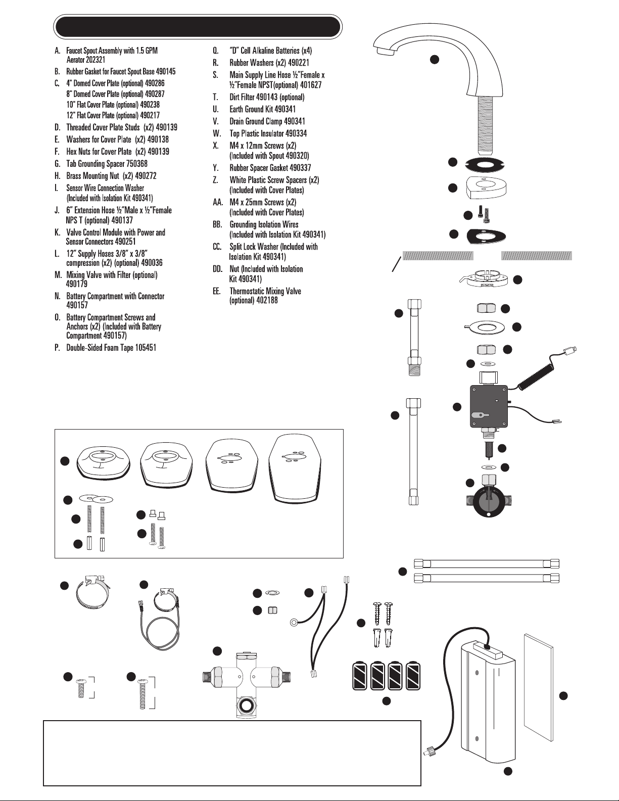
AutoFaucet®PartsList
W
B
A
H
H
I
Y
X
BB
CC
DD
CoverPlates
SINK or COUNTERTOP
x2
x2 25mm
Z
C
E
D
F
AA
Tools Required: Basin or Crescent wrench, slotted and Phillips screwdriver
Optional TC Faucet Universal Tool #490142
J
K
L
M
T
N
P
O
Q
R
R
S
4" 8" 10" 12"
X
EE
Optional Aerators Available:
0.5 GPM (vandal resistant) #401190
1.5 GPM (vandal resistant) #401213
1.5 GPM Laminar flow #401214
2.0 GPM (vandal resistant) #401148
Optional AC Adapters:
Single unit AC adapter #490099
6 - unit AC adapter box #490071
AC wire assembly #490100
NOTE: An AC wire assembly needs to be
ordered for each faucet when purchasing
the 6 - unit AC adapter box.
2
U
V
G
12mm
AA

IMPORTANT - DO NOT USE PIPE DOPE OR TEFLON TAPE FOR
ANY FAUCET OR SUPPLY CONNECTIONS!
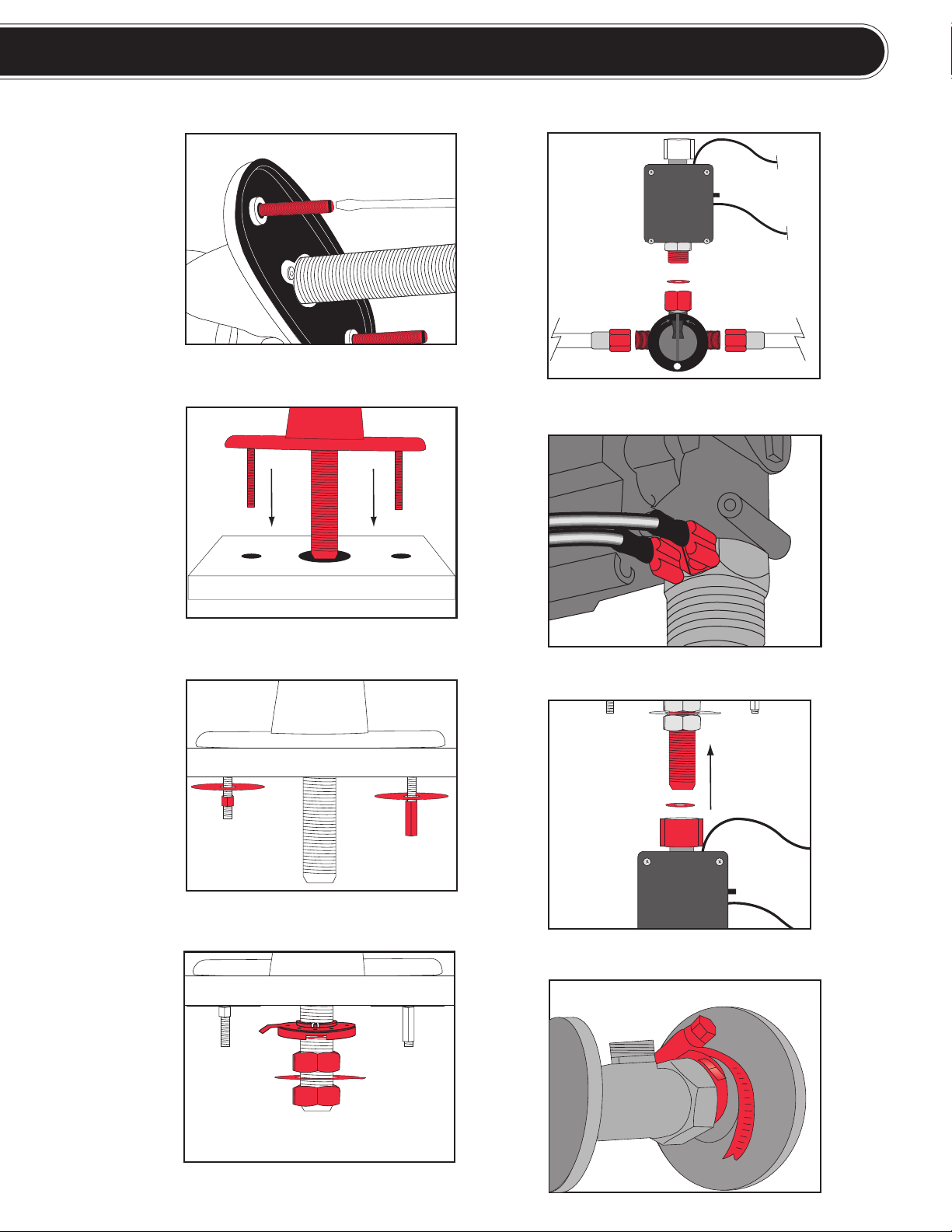
Step 1
Attach both threaded studs (D) to the bottom of the semi-assembled cover plate.
Step 2
Guide the semi-assembled faucet spout through the 3-hole 4” or 8” center set in counter or
sink.
Step 3
Finish securing the cover plate from underneath by placing the two metal washers (E) on to
each of the threaded studs. Secure with hex nut (F) and hex nut (DD).
Step 4
Secure the spout by using the following components in sequential order:
a. Tab grounding spacer (G) (brass washer needs to be on top)
b. Brass mounting nut (H)
c. Sensor wire connection washer (I) [IMPORTANT: Make sure this washer’s tab is
rotated 180° from the tab grounding spacer (G).]
d. Brass mounting nut (H)
Step 5
Connect the two 12” supply hoses (L) to the mixing valve (M). Place the rubber washer (R) into
module (K).
Step 6
Connect the earth ground wire (U) to one side of the U-tab. Then connect the yellow sleeved
drain ground connector, located on the Grounding Isolation Wires (BB), to the other side of the
brass U-tab.
Step 7
Hand tighten the valve control module assembly to the faucet shank.
NOTE: Make sure the black rubber washer is in the white plastic nut before connecting the
valve control module to the faucet shank.
Step 8
Mount the earth ground clamp to the cold water supply pipe.
Instructions continued on reverse side
Installing Your New Faucet
3
4
Step1
Step3
Step4
Step2
COLD
HOT
Step5
Step7
Step6
Step8

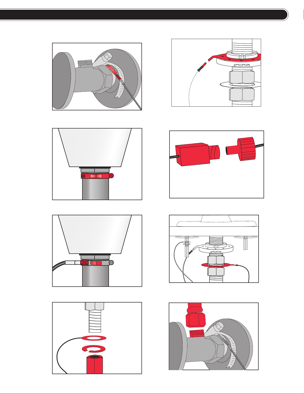
Step 9
Connect the longer green earth ground wire to the clamp tab.
Step 10
Mount the drain ground clamp to the metal drain tail stock as close to the sink as possible.
Step 11
Connect the brass plated end (black sleeved) of the green Grounding Isolation Wires (BB) to the drain ground
clamp tab (V).
Step 12
Connect the ring terminal on the green Grounding Isolation Wires (BB) to the stud with the hex nut (DD).
Continue fastening with lock washer (CC) and hex nut (F). [NOTE: For single-hole mounted faucets remove
the ring terminal wire with wire cutters.]
Step 13
Connect the other end of the green Grounding Isolation Wires (BB) to the tab grounding spacer(G).
Step 14
See battery compartment installation instructions below. Then connect the battery power connector wires
control module indicating that the faucet is installed properly.
Step 15
Connect the black sensor wire to the sensor washer (I).
Step 16
Connect the water supply hoses (L) to the valve stops. Turn on the hot and cold water supply and test faucet.
NOTE:
· If the optional 6” extension hose (J) is used between the valve control module (K) and the faucet shank
connection (to lower the unit down for accessibility), the rubber washer (R) is not required.
· If this is an AC adapter installation, skip “Battery Compartment Installation” and use instructions
supplied with the AC adapter.
Battery Compartment Installation
1. Remove battery compartment cover by unscrewing the two Phillips screws. Inside the battery compartment
(N) there are two large screws and anchors (O). Place the battery compartment (N) in a convenient location
ensuring easy access.
2. Secure to wall using screws and anchors (O) or double-sided tape (P).
3. Install four (4) “D” cell alkaline batteries (Q). Replace cover on battery compartment. Connect battery box
connector to valve power connector. Once power is established, you will hear a clicking sound when you
place your hand under the faucet.
4. Turn water supply on. The water will automatically come on when you place your hand under the faucet.
The water will stay on for a maximum of 15 seconds as long as your hands are under the faucet, and
moving. The water will shut off after you remove your hands from the sensing zone or water stream.
5. Verify water supply connections are not leaking.
Setting Water Temperature Mix
1. There is a temperature dial on the mixing valve (M). Use a screwdriver to loosen the screw on the dial.
[To add hot water, turn the knob to the right or to the left to add cold water. ]
2. Once you have the desired water mix temperature, lock the control knob in place with a screwdriver.
3. There is a temperature adjustment on the optional thermostatic mixing valve (FF). Use an allen wrench to
turn adjustment screw to add hot or cold water.
5
6
Step 14
Step 11
Step 10
Step9
Step 12 Step 16
Step 13
Step 15

IMPORTANT: Must have
tight connection to
metal supply line!
H
C
H
(green)
(green)
(green)
RED INDICATOR
RESET BUTTON
OPEN
AUTO
Figure1
attach to drain
IMPORTANT: Must have
tight connection
around drain!
IMPORTANT: All Wires
MUST BE connected
as shown! IMPORTANT: All Wires
MUST BE connected
as shown!
Note: Above counter parts
come pre-assembled.
7
Black Sensor Wire
MANUAL
OVERRIDE
DIAL
Drain Ground Wire
Earth Ground Wire
EDD
D
L
N
K
M
I
G
H
H
U
R
R
T
BB
CC
F
T
WAA
Y
A
C
B
Z

Troubleshooting Guide
Install issues due to drainpipe
obstructions
Drain pipe or other plumbing under the
sink or countertop is in the way.
Use the optional flexible 6” extension hose (J). It is to be placed between the spout shank (A) and the outlet
of the valve control module (K). The faucet components can then be assembled off to one side of the drain or
other plumbing. Do not add any plumbing or piping components not Included in this kit to the faucet installation
as it may cause the faucet to not function or sense properly.
Faucet not working
(No flashing red LED located
on valve
control module)
Batteries not inserted
correctly
Improper or poor connection to
power supply
Remove cover from battery box (N) check that the batteries (Q) have been inserted to the correct orientation and
are making connection to the contacts. Refer to the battery icons located on the base of the battery box tray.
Check that the connection from the battery box is fully inserted into the female connector on the valve control
module (K) and assure the connector round thumbnut is fully fastened.
Faucet not working and no
water flows
when activated
(Red LED is flashing)
Low batteries
Water source valves turned off
Sensor shorted to ground or unit
unable to calibrate
Improper ground connection
Broken or corrupt sensor wire or
defective valve control module
electronics.
If red indicator is flashing 5 times every 4 seconds, replace with new Alkaline batteries (Q).
Open water source valves and check that there is water flow.
If red indicator is flashing once or multiple times every 4 seconds, there is a problem with the installation and the
sensor is shorted. To verify the valve control module is working correctly, carefully disconnect the black sensor
wire from the connection washer (I). With the wire disconnected, touch the connector at the end of the black wire
with your fingers. The sensor should activate and water should come on. Let go of the connector and the water
should shut off. If the unit works as described above, it malfunctions when you reconnect the black sensor wire to
the spout assembly, then there is an error in the spout and cover plate installation. If the faucet does not activate
as described when touching the sensor connector, then you have a grounding issue or there is a broken sensor
wire (see troubleshooting below).
If you can touch any of the steel braided supply hoses, the brass fitting on the valve control module, or the mixing
valve and it activates the unit, there is improper earth grounding (U). Verify that the ground clamp (U) has been
installed and recheck the connections. Verify the clamp is tightly fastened directly to the copper pipe for a proper
ground connection. Press reset button on valve control module after making any adjustments.
If the connector has broken off of the black sensor wire or the valve control module appears to be defective
please contact Technical Concepts. Do not attempt to repair the valve control module (K) or sensor wire.
Intermittent cycling and/or water
runs on after actuation
Poor sensor washer and
wire connection
Verify the brass nuts (H) that fasten the connection washer (I) are fully tightened. Reconnect the sensor wire to
the washer. Press reset button on valve control module after making any adjustments
Insufficient ground connection
SST faucet components are in
contact with metal parts of the sink
or plumbing.
Be sure that all of the SST faucet components (cover plate, white plastic screw spacers, brass shank, metal
washer, braided hoses) or any components for the sink (metal sink lip / mounting hardware) or countertop (i.e.
metal support brackets / structural parts) are not in contact and are spaced from each other. Press reset button
on valve control module after making any adjustments
Verify that the earth ground clamp (U) has been installed and recheck the connections. Verify the clamp is tightly
fastened directly to the copper pipe for a robust ground connection. Press reset button on valve control module.
Intermittent cycling and /or
faucet actuation is overly
sensitive
Isolation parts are not installed or
not installed correctly.
If you can touch the sink and the faucet activates, the unit installation is improper. Check that isolation
components (W, Z, & G) are used and installed correctly. If the sink is of a metal composition, verify the
sink ground connection (BB) is in place and installed properly.
Faucet doesn’t shut off after
you pull your hands away
Check that the drain ground (V) is assembled to the threaded portion of the metal drain ring (not on
the pipe) and is connected to the tab on the valve control module (K). Press reset button on valve
control module after making any adjustments.
Drain grounding not connected or
assembled.
There is sensor short to ground or
unit is not calibrating.
Press reset button located on the face of the valve control module (K). The valve should close and the
water will stop running. Let unit recalibrate for 20 seconds and verify faucet activation. If water continues to
run, then there is an error in the installation and grounding scheme (see troubleshooting above).
Water stays on
Dial set to the “open” position or not
turned to the full “auto” position
Turn the knob on the side of the valve control module (K) fully to the “auto” position (until it hits the stop)
and actuate the faucet by placing your hand near the spout. Water should stop running and unit will return
to the normal idle operation mode when you remove your hand from the spout.
Turn off water source valves. Remove aerator from end of the spout (A) and examine for dirt and particu-
lates. Inspect and clean input dirt filter (T). Reinsert filter and turn water source back on. Actuate faucet
several times without the aerator installed to flush any debris from the valve mechanism until dripping has
ceased. Reinstall aerator.
Turn the knob on the side of the valve control module (K) fully to the “auto” position (until it hits the stop) and
actuate the faucet several times by placing your hand near the spout. Water should stop running or dripping
and unit will return to the normal idle operation mode once you remove your hand from the spout.
Dial not turned to the full
“auto” position
Debris or particulate matter is
trapped in valve
Leaky faucet
First check that the water supply line valves are fully open and the lines are not restricted. If water flow is
not as desired, optional sized aerators to control water flow (0.5 & 2.0 GPM) can be purchased.
Size of aerator or water
supply flow
Increase or decrease
water flow
Install a mixing valve (M). Adjustments can be made to the valve by resetting the temperature control
knob. If more precise or anti scald water temperature control is required, the optional thermostatic control
valve (FF) may need to be purchased.
Turn the knob on the side of the valve control module (K) to the “open” position to flush faucet. This is a
mechanical override of the automatic sensing and will set the valve to a constant open position. Once the
water is flushed as required, turn the knob back fully to the “auto” position (until it hits the stop) and cease
water flow by placing hand near faucet and pulling hand away.
Required hygiene or sanitary
procedure
No mixing valve installed or mixing
valve needs adjustment
Flushing faucet for regulatory
protocol
Water temperature too hot
or cold
Problem Cause Solution
For technical assistance, please call 1.800.551.5155
Web: www.technicalconcepts.com Email: [email protected]
Tehcnical Concepts LLC.
1301 Allanson Road, Mundelein, Illinois 60060 U.S.A • 1-847-837-4100 • FAX: 1-800-551-5046 107199A Rev 2 12/07
1
2
3
4
5
6
7
8
9
10
11
Table of contents
Other Technical Concepts Plumbing Product manuals


Popular Plumbing Product manuals by other brands


Blanco
Blanco BlancoDiamond 511-710 Specification sheet

Hans Grohe
Hans Grohe AXOR Starck 10859 0 Series Installation/User Instructions/Warranty

Villeroy & Boch
Villeroy & Boch My Nature SC instruction manual

Toto
Toto TLP02301 Operation manual

saunalife
saunalife Ergo E7 Series manual

Dundalk LeisureCraft
Dundalk LeisureCraft Cedar Assembly instructions