manuals.online logo
Brands
  1. Home
  2. •
  3. Brands
  4. •
  5. Technics
  6. •
  7. Cassette Player
  8. •
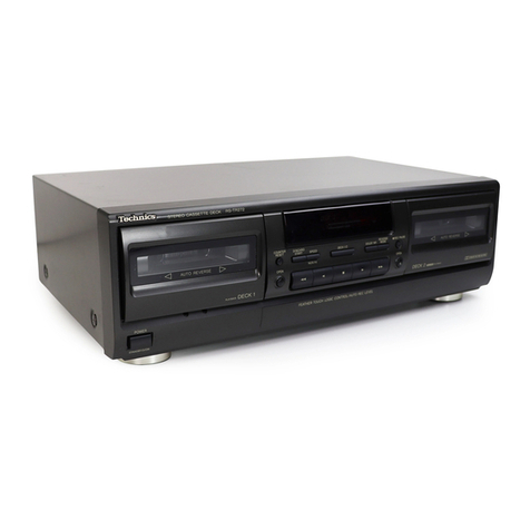
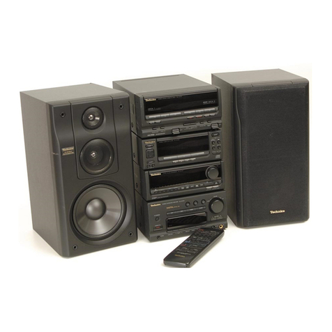
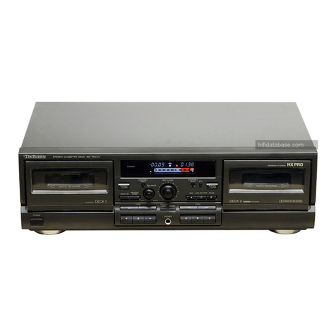
  9. Technics RS-CH770 User manual

Technics RS-CH770 User manual

This manual suits for next models

2

Other Technics Cassette Player manuals
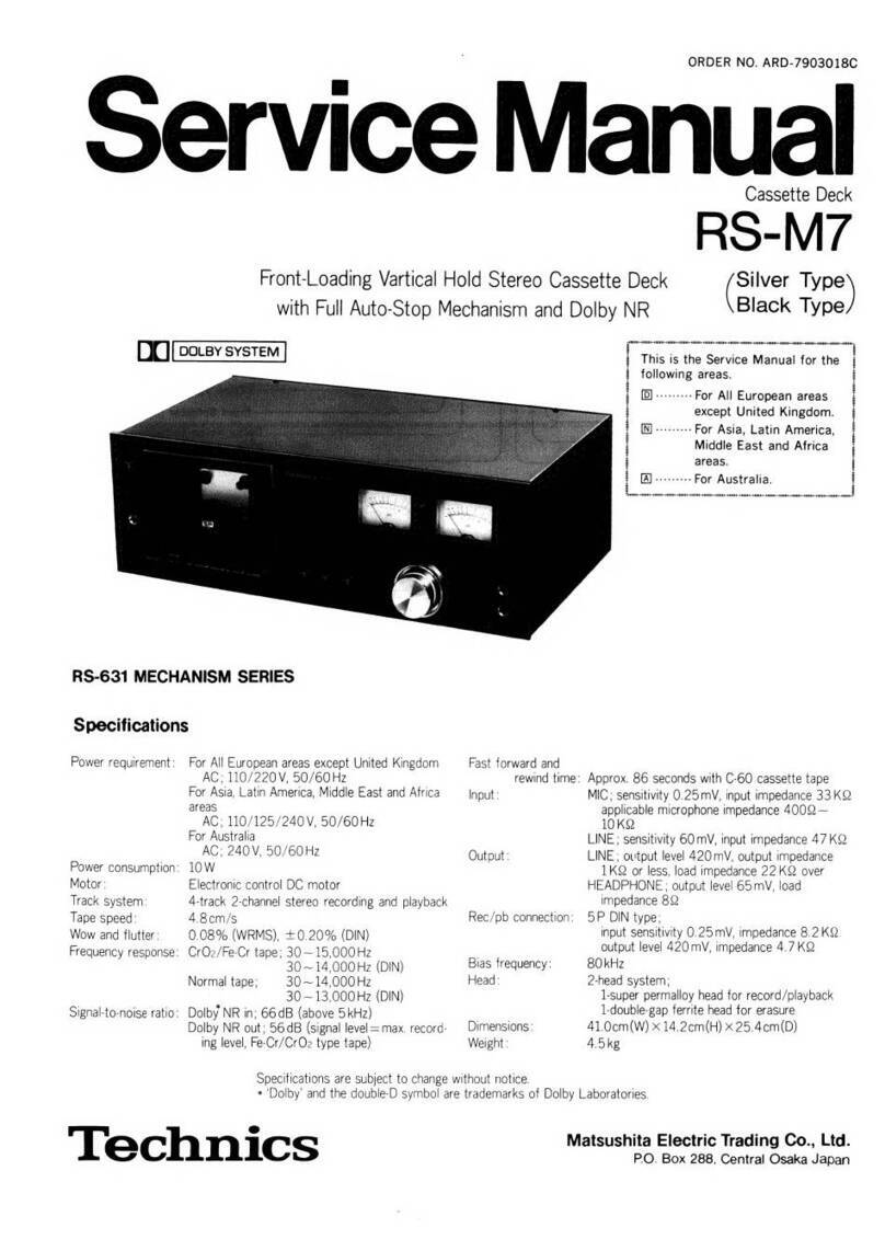
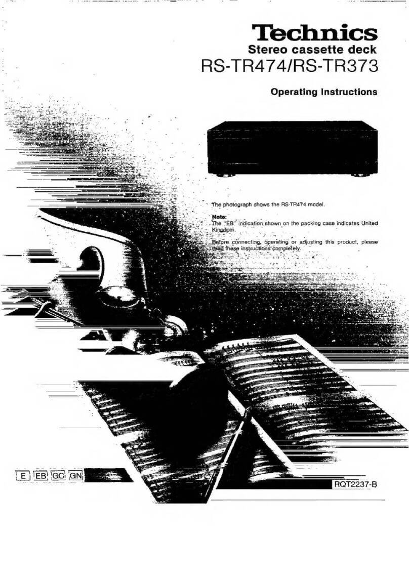
Technics RS-BX501 - SERVICE User manual

Technics

Technics RS-BX501 - SERVICE User manual

Technics RSTR155 - DUAL CASS RECORDER User manual

Technics

Technics RSTR155 - DUAL CASS RECORDER User manual

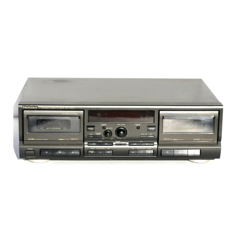
Technics RS-TR575M2 User manual

Technics

Technics RS-TR575M2 User manual

Technics RS-B14 User manual

Technics

Technics RS-B14 User manual

Technics RS-DV250 User manual

Technics

Technics RS-DV250 User manual

Technics RS-M235X User manual

Technics

Technics RS-M235X User manual

Technics RS-B11W User manual

Technics

Technics RS-B11W User manual

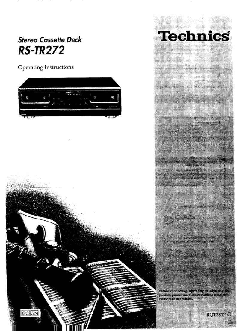
Technics RSTR272 - DUAL CASS. RECORDER User manual

Technics

Technics RSTR272 - DUAL CASS. RECORDER User manual

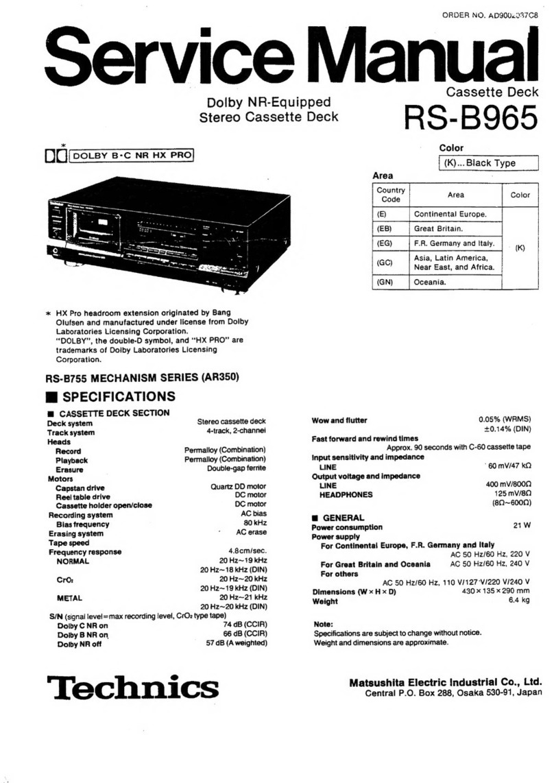
Technics RS-B965 User manual

Technics

Technics RS-B965 User manual

Technics RS-TR474 User manual

Technics

Technics RS-TR474 User manual

Technics RS-CA01 User manual

Technics

Technics RS-CA01 User manual

Technics RS-DC10 User manual

Technics

Technics RS-DC10 User manual

Technics RSTR272 - DUAL CASS. RECORDER User manual

Technics

Technics RSTR272 - DUAL CASS. RECORDER User manual

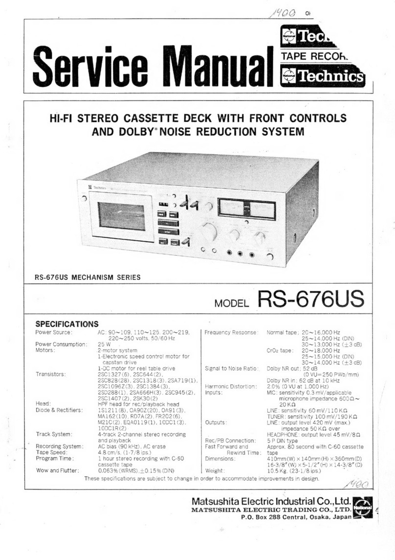
Technics RS-676US User manual

Technics

Technics RS-676US User manual

Technics RS-BX606 User manual

Technics

Technics RS-BX606 User manual

Technics RS-M215 User manual

Technics

Technics RS-M215 User manual

Technics RS-AZ6 User manual

Technics

Technics RS-AZ6 User manual

Technics RS-DV290EG User manual

Technics

Technics RS-DV290EG User manual

Technics RS-M225 User manual

Technics

Technics RS-M225 User manual

Technics RS-TR333 - SCHEMATICS User manual

Technics

Technics RS-TR333 - SCHEMATICS User manual

Technics RS-TR474 User manual

Technics

Technics RS-TR474 User manual

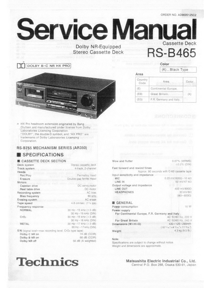
Technics RS-B465 User manual

Technics

Technics RS-B465 User manual

Technics RSTR272 - DUAL CASS. RECORDER User manual

Technics

Technics RSTR272 - DUAL CASS. RECORDER User manual

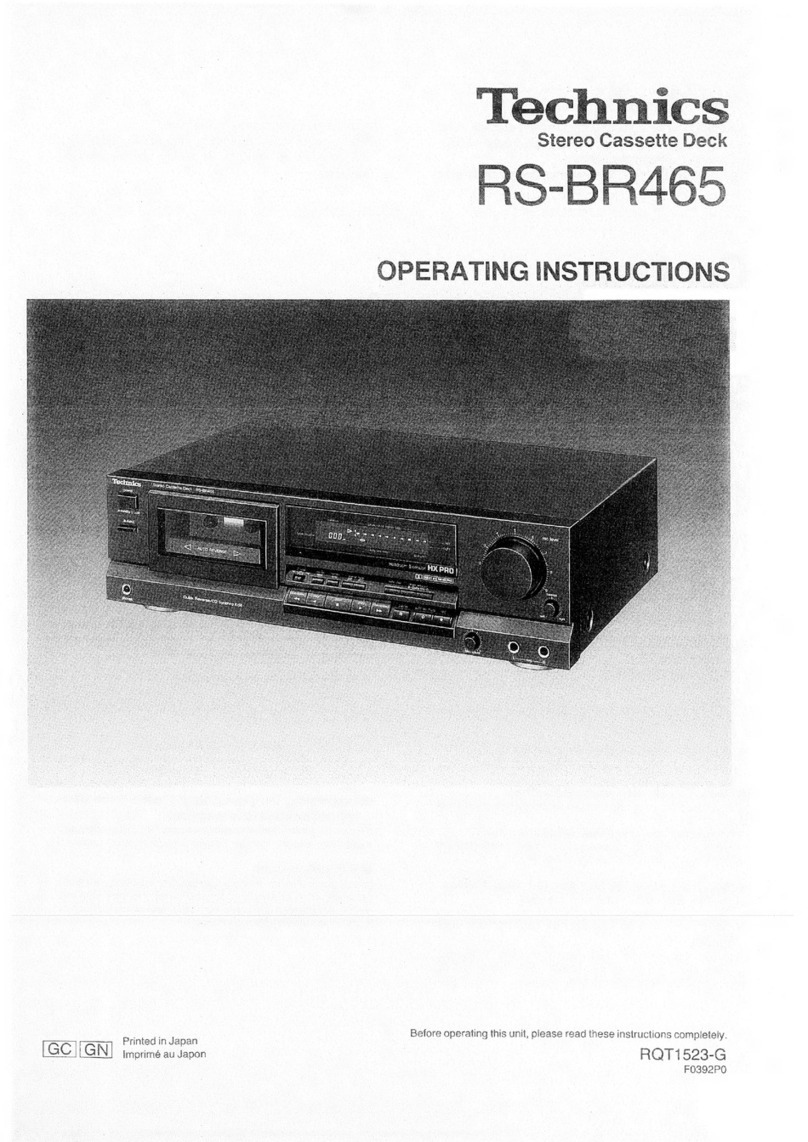
Technics RS-BR465 User manual

Technics

Technics RS-BR465 User manual
Popular Cassette Player manuals by other brands

Ahuja CPA-360 Operation manual

Ahuja

Ahuja CPA-360 Operation manual

Sony Pressman TCS-60DV Specifications

Sony

Sony Pressman TCS-60DV Specifications

Philips AQ6485/14 Product information

Philips

Philips AQ6485/14 Product information

Sony TCM-200DV - Cassette Recorder operating instructions

Sony

Sony TCM-200DV - Cassette Recorder operating instructions

Nakamichi BX-300 Service manual

Nakamichi

Nakamichi BX-300 Service manual

Panasonic RQ-E25V operating instructions

Panasonic

Panasonic RQ-E25V operating instructions

Aiwa TP-VS535 operating instructions

Aiwa

Aiwa TP-VS535 operating instructions

Yamaha MT8X Operation manual

Yamaha

Yamaha MT8X Operation manual

Sherwood Newcastle D-480 operating instructions

Sherwood

Sherwood Newcastle D-480 operating instructions

Manta MA408 user manual

Manta

Manta MA408 user manual

GPO W0162B user guide

GPO

GPO W0162B user guide

Marantz CP230 Service manual

Marantz

Marantz CP230 Service manual

Sony HST-471 Service manual

Sony

Sony HST-471 Service manual

Sharp JC-AV1 Operation manual

Sharp

Sharp JC-AV1 Operation manual

Pioneer CT-W103 Service manual

Pioneer

Pioneer CT-W103 Service manual

Sony CFS-B15 - Am/fm Stereo Cassette Recorder operating instructions

Sony

Sony CFS-B15 - Am/fm Stereo Cassette Recorder operating instructions

Sony WMFS220 - Portable Sports AM/FM Cassette... operating instructions

Sony

Sony WMFS220 - Portable Sports AM/FM Cassette... operating instructions

Aiwa HS-TA21 operating instructions

Aiwa

Aiwa HS-TA21 operating instructions

manuals.online logo
manuals.online logoBrands
  • About & Mission
  • Contact us
  • Privacy Policy
  • Terms and Conditions

Copyright 2025 Manuals.Online. All Rights Reserved.

ORDER
NO.
AD9603056C8
Service
Manual
Stereo
Cassette
Deck
Cassette
Deck
System:
SC-CH770
OU
[DOLBY
B
NR
|*’
R
S
=
C
+
vA
vA
O
*2.*3
§B-CH770
*2,*3
SB-PC10
*2.*9
SB-CH770
ST-CH770
SL-CH770
Colour
(K)
:
Black
ySBPSIO
poe
Suffix
for
Area
Colour
Model
No.
Europe,
Asia,
Latin
America,
Middle
East,
Africa
and
Oceania
*2,*3
SB-PS10
RS-CH770
SE-CH770
Remote
Control
Transmitter
System:
SC-CH570
*2.*3
§B-CH570
*2.*3
SB-PC570
*2.*3
SB-CH570
*2
$B-PS570
#
*2$B-PS570
*1:
Dolby
noise
reduction
manufactured
under
or
i
i
i
or
license
from
Dolby
Laboratories
Licensing
*3SB-PS10
|
So
ee
as
|
gai?
SB-PS10
Corporation.
:
as,
re
“Dolby”
and
the
double-D
symbol
are
trade
marks
of
Doiby
Laboratories
Licensing
Corporation.
Remote
Control
Transmitter
RS-CH770
SE-CH570
AR-2
MECHANISM
SERIES
Specifications
(IH
F
78)
Frequency
response
(Dolby
NR
off)
.
TYPE
I
(NORMAL)
20
Hz-1
6
kHz
(DIN)
@
Cassette
Deck
Section
TYPE
II
(HIGH)
20
Hz-1
6
kHz
(DIN)
Deck
system
Stereo
cassette
deck
TYPE
IV
(METAL)
20
Hz-1
6
kHz
(DIN)
Track
system
4-track,
2-channel
S/N
(signal
level
=
max
recording
level,
TYPE
II
type
tape)
Recording
system
AC
bias
NR
off
56
dB
(A
weighted)
Bias
frequency
100
kHz
Dolby
NR
B
on
66
dB
(A
weighted)
Erasing
system
AC
erase
Input
sensitivity
and
impedance
Heads
REC
(IN)
400
mV/23
kQ
DECK
1
Playback
head
(Permalloy)
x
1
Output
voltage
and
impedance
DECK
2
Recording/Playback
head
(Permalloy)
x 1
PLAY
(OUT)
280
mV/360
O
Erasing
head
(Double-gap
ferrite)
x
1
Hi
General
Motors
: ;
DECK
1,
2
Capstan
drive
(DC
servo
motor)
=
1
Dimensions
(W
x
Hx
D)
270
x
118.5
«
269.5
mm
Tape
speed
4.8
cm/sec.
weelant
1.9
kg
Wow
and
flutter
0.16%
(WRMS)
Notes:
Fast
forward
and
rewind
times
Specifications
are
subject
to
change
without
notice.
Approx.
110
seconds
with
C-60
cassette
tape
Weight
and
dimensions
are
approximate.
Tuner/sound
Compact
disc
el
System
processor
player
Amplifier
Cassette
deck
|
Front
speakers
|
Center
speaker
|
Surrournd
speakers
SC-CH770
ST-CH770
SL-CH770
SE-CH770
¥2.*3SB-CH770
|
*2°°SB-PC10
|
*°°3
SB-PS10
*2
SB-PT570
SC-CH570
ST-CH570
SL-CH570
sE-cH5s70
|
FS
CH770
|
s2s358.cH570
|
“SB-PCS70
*2SE3-PS570
*3SB-PT570A
*3
SB-PC570
“8S
B-PS10
*2
For
Europe
area:
oo...
Made
in
PAES
*3
Except
for
Europe
area:
.....
Made
in
NABEL
©
1996
Matsushita
Electric
Indusiriaal
Co.,
Ltd.
e
®
:
All
rights
reserved.
Unauthorized
c
©pying
i
ec
]
and
distribution
is
a
violation
of
law.
re
RS-CH770
A\WARNING
This
service
information
is
designed
for
experienced
repair
technicians
only
and
is
not
designed
for
use
by
the
general
public.
It
does
not
contain
warnings
or
cautions
to
advise
non-technical
individuals
of
potential
dangers
in
attempting
to
service
a
product.
Products
powered
by
electricity
should
be
serviced
or
repaired
only
by
experienced
professional
technicians.
Any
attempt
to
service
or
repair
the
product
or
products
dealt
with
in
this
service
information
by
anyone
else
could
result
in
serious
injury
or
death.
Location
of-
Controls
iscetei
es
hick
aie
eee
eisai
etanariann
Cotas
aks
2
Wiring
Connection
Diagram
Operation
Check
and
Function
oflG
Terminals:
23,
ccecsse.cscesecesdauseavivesctds
ay
tice
vals
aan
Main
Component
Replacement
Procedures
0...
eee
3~12
Block
Diagram
.......ccceeccseetseetereee
Service
Mode
Function
of
Cassette
Mechanism...
13,14
Replacement
Parts
List
oe
Measurements
and
Adjustments
........
cece
ecceceeeerserecteeetiieens
15~17
Cabinet
Parts’
Location
iin.
ii.
itie
ities
aude
eens
neinarieaGane
Schematic
Diagram
occ
erect
eeseeeereees
Mechanism
Parts
Location
Printed
Circuit
Board
Diagram
uo...
cece
ce
cererrseeeeeetsereeeens
NOTE:
Refer
to
the
service
manual
for
Model
No.
SE-CH770
(ORDER
No.
AD9603055C8)
or
SE-CH570
(ORDER
No.
AD9603054C8)
for
information
on
“Accessories”,
“Stacking
the
Components”,
“Connections”
and
“Packaging”.
@
Location
of
Controls
G@)
Deck
1
cassette
holder
@
Deck
1
indicator
(DECK
1)
3)
Deck
1/deck
2
select
button
(DECK
1/2)
(4)
Reverse
mode
select
button
(REV
MODE)
()
Deck
2
cassette
holder
©
Dolby
noise
reduction
button
(DOLBY
NR)
@
Record
pause
button
(@
REC
PAUSE)
Record
pause
indicator
(REC
PAUSE)
@)
Deck
2
indicator
(DECK
2)
Deck
1
cassette
holder
open
button
(4
OPEN)
@)
Counter
reset
button
(RESET)
42)
Counter
display
button
(DISPLAY)
(3
Fast
forward/rewind/tape
program
sensor
buttons
(<<,
>>)
Playback
buttons
and
indicators
(<1,
>>)
@®
Stop
button
(0)
Tape
edit
buttons
(TAPE
EDIT,
NOR,
HIGH)
@)
Deck
2
cassette
holder
open
button
(4
OPEN)
RS-CH770
i
OPERATION
CHECKS
AND
MAIN
COMPONENT
REPLACEMENT
PROCEDURES
1.
This
section
describes
procedures
for
checking
the
operation
of
the
major
printed
circuit
boards
and
replacing
the
main
components.
2.
For
reassembly
after
operation
checks
or
replacement,
reverse
the
respective
procedures.
Special
reassembly
procedures
are
described
only
when
required.
3.
Select
items
from
the
following
index
when
checks
or
replacement
are
required.
4.
illustrated
screws
are
equivalent
to
actual
size.
5.
Refer
the
parts
No.
on
the
page
of
“Main
Component
Replacement
Procedures”,
if
necessary.
e
Contents
*Checking
Procedure
for
each
P.C.B.
Page.
1.
Checking
for
the
main
P.C.B.
and
power
supply
P.C.B..sseeeceeecceecccsccccccccccescsecescvses
ee
34.
2.
Checking
for
the
operation
P.C.B..
Coo
omer
eererererereseesereoesreesereenecseneseseeeeeoer
oe
56,
«Main
Component
Replacement
Procedures
1.
Replacement
for the
cassette
lid
ass'y,
se
eereecereccccsccsescesescccssesceseseeseesesvvcsvoce
7.
2.
Replacement
for the
cassette
holder,
s*eeecercsccsccrvecvereeccccveesesesesesesesesesecesenes
7:
3.
Replacement
for
the
motor
ass’y,
capstan
belt
and
winding
belt.
sesercerreseeccceercesccscscveeeeeee
8.44,
4.
Replacement
for the
plunger
ass’y
and
the
parts
mounted
on
mechanism
P.C.B..
seeececerceeesesccevess
14.42,
5.
Replacement
for
the
head
block
and
pinch
roller
ass’y.sseesecceccesccsvccsscsscessscescsecsceve
se
t2
Mi
Checking
Procedure
for
each
P.C.B.
1.
Checking
for
the
main
P.C.B.
and
power
supply
P.C.B.
Remove
the
top
cabinet.
Cup
@x4
()\
mp
©
(Black)
[RHD30007
-
K1]
(ID
©
Black)
[XTBS3+8JF-Z1]
RS-CH770
Remove
the
flat
cable
from
connector.
cD
Release
the
4
claws,
and
then
remove
the
front
panel
ass’y.
Connector
(CN901-—1/CNS01—2)
Main
P.C.B.
Connect
the
flat
cable
to
the
connector.
Connector
(CN6O1A)
Release
the
2
claws,
and
then
remove
the
power
supply
P.C.B..
Socket
(CN601B)
Power
supply
P.C.B.
t
step
9
Connect
the
socket
(CN601B)
to
the
connector
(CN601A).
*
Check
the
main
P.C.B.
and
power
supply
P.C.B.
as
shown
below.
Main
P.C.B.
istep
10)
Connect
the
lead
wire.
Cabinet
Place
the
power
supply
P.C.B.
on
the
insulation
material
not
to
short-circuit
the
solder
side
of
power
supply
P.C.B..
(i)
+
(Black)
[XTBS3HJFZ1]
RS-CH770
2.
Checking
for
the
operation
P.C.B.
Press
the
eject
rod
in
the
direction
of
arrow,
and
then
open
the
cassette
holder.
+
Follow
the
@eamp
~
of
the
item
1
in
checking
procedure
for
each
P.C.B.
on
pages
3
and
4.
Cassette
holder
(DECK1)
Cassette
holder
(DECK2)
Remove
the
shield
plate
(L)
/
(R).
Shield
plate
(L)
Shield
plate
(R)
Release
the
claw,
and
then
remove
the
mechanism
unit.
Remove
the
cassette
lid
ass’y
in
the
direction
of
arrow.
Cassette
lid
ass'y
(DECK1)
Cassette
lid
ass’y
(DECK2)
Release
the
2
claws.
(SID
©
(Black)
[XTB3+1
OJFZ]
(3)
‘bY
[XTBS26+10J]
RS-CH770
|
Remove
the
deck
mecha
frame
in
the
direction
of
arrow.
Remove
the
operation
P.C.B..
Operation
P.C.B.
Connect
the
flat
cable
to
the
connector.
\
Connector
(CN601A)
Socket
(CN601B)
Power
supply
P.C.B.
aD
Connect
the
socket
(CN
601B)
to
the
connector
(CN6(4A).
¢
Check
the
operation
P.C.B.
as
shown
below.
Operation
P.C.B.
Connect
the
lead
wire
NOTE
Place
the
power
supply
P.C.B.
on
the
insulation
material!
not
aes
to
short-circuit
the
solder
side
GND
plate
of
power
supply
P.C.B..
Cabinet
eae
|
_
RS-CH770
i
Main
Component
Replacement
procedures
1.
Replacement
for
the
cassette
lid
ass’y
+
Follow
the
G2aD
~
GED
of
the
item
1
in
checking
procedure
for
each
P.C.B.
on
page
3.
Cassette
holder
(DECK2)
Cassette
holder
(DECK1)
c=
Press
the
eject
rod
in
the
direction
of
arrow,
and
then
open
the
cassette
holder.
Eject
rod
Remove
the
cassette
lid
ass’y
in
the
direction
of
arrow.
Cassette
lid
ass'y
(DECK1)
(RYF0412-K]
Cassette
lid
ass'y
(DECK2)
[RYF0413-K]
2.
Replacement
for
the
cassette
holder
*
Follow
the
G&D
~
GEEED
of
the
item
1
in
checking
procedure
for
each
P.C.B.
on
pages
3
and
4.
M@
Open
spring
installation
*
Follow
the
ZUR
~
of
the
item
2
in
checking
Cassette
holder
ass'y
procedure
for
each
P.C.B.
on
pages
5
and
6.
(DECK1)
[RFKLACH430GA]
Cassette
holder
ass
y
(DECK2)
——,
[RFKLACH430GB]
»
Release
the
lug
of
Cassette
holder
Sy
in
the
direction
of
arrow.
RS-CH770
3.
Replacement
for
the
motor
ass’y,
capstan
belt
and
winding
belt
+
Follow
the
@25ED
~
GREED
of
the
item
1
in
checking
procedure
for
each
P.C.B.
on
pages
3
and
4.
*
Follow
the
G&D
~
G&D
of
the
item
2
in
checking
procedure
for
each
P.C.B.
on
page
5.
Mechanism
P.C.B.
SG
5
|
aun
qs,
NOTE
Kr
ie
Ea
wi
ue
Handle
the
connector
)
aN
:
;
with
care
so
that
me
When
removeing
the
Oe
4
3
LTS:
a
shape
of
terminals
mechanism
control
P.C.B.,
;
be
toe
Rae
nae
i.
:
different
from
others.
remove
it
with
holding
the
¥
=
mechanism
P.C.B.
by
finger.
Unsolder
the
terminals.
Release
the
claw,
and
then
remove
the
main
P.C.B..
The
illustration
below
shows
DECK2
mechanism.
For
DECK1
mechanism,
perform
the
same
procedure
as
DECK2.
Remove
the
sub
chassis.
Head
connector
Re
€
its
Remove
the
P.C.B.
support.
ex)
hs
;
(se)
ump
ra)
Release
the
2
claws,
:
and
then
remove
the
.
head
connector.
a
:
XTBS26+8]
f)ump
©
XTW26+10S]
RS-CH770
@)p
©
[RHD26022]
Motor
ass'y
[REM0055]
Capstan
belt
[RDV0034]
Remove
the
flywheel
R.
Winding
belt
[RDV0033-1]
|
Release
the
2
calws,
and
then
step
11
remove
the
winding
belt
and
Remove
the
flywheel
F,
SPN9-
Put
the
winding
belt
on
the
flywhe
el
F.
Veh
The
boss
and
marking
should
be
positioned
horizontally.
F
lywheel
F
Winding
belt
Tweezers
Install
the
flywheel
F.
NOTE
Take
care
not
stick
the
grease
onthe
belt.
Put
the
winding
belt
on
the
pulley
temporarily.
RS-CH770
The
winding
lever
should
be
positioned
as
shown
below.
Winding
lever
Capstan
belt
A
(Side
view)
Winding
arm
Install
the
winding
lever
and
spring
while
pressing
the
winding
arm
in
the
direction
of
arrow.
(The
winding
lever
must
be
inserted
completly
and
latched
with
claws.)
Put
the
capstan
belt
A
temporarily
as
shown
below.
dss
505:
Boss
Capstan
belt
A
Install
the
sub
chassis
to
the
mechanism,
and
then
tighten
screws.
Mechanism
~10-
@)mm
0
[XTW226+10S]