manuals.online logo
Brands
  1. Home
  2. •
  3. Brands
  4. •
  5. Technics
  6. •
  7. Stereo Receiver
  8. •
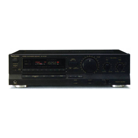
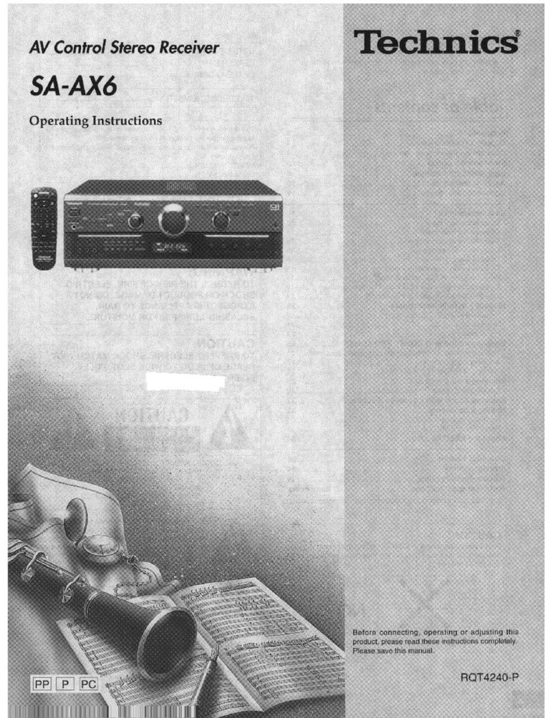
  9. Technics SA-EX300 User manual

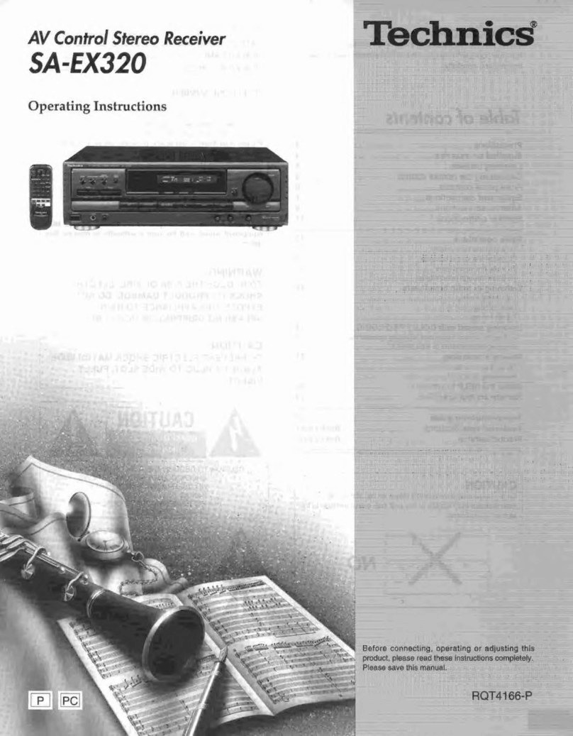
Technics SA-EX300 User manual

Other manuals for SA-EX300

2

This manual suits for next models

1

Other Technics Stereo Receiver manuals
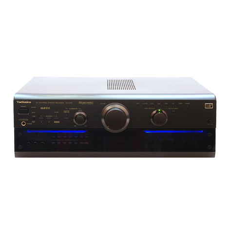
Technics SA-EX510; SA-EX410; SA-EX310 User manual

Technics

Technics SA-EX510; SA-EX410; SA-EX310 User manual

Technics QUARTZ SA-R330 User manual

Technics

Technics QUARTZ SA-R330 User manual

Technics SA-5250 User manual

Technics

Technics SA-5250 User manual

Technics SADX930 - RECEIVER User manual

Technics

Technics SADX930 - RECEIVER User manual

Technics SA-203 User manual

Technics

Technics SA-203 User manual

Technics SA-5570 User manual

Technics

Technics SA-5570 User manual

Technics SU-CH700 User manual

Technics

Technics SU-CH700 User manual

Technics SAAX6 - RECEIVER User manual

Technics

Technics SAAX6 - RECEIVER User manual
Technics SA-EX120 User manual

Technics

Technics SA-EX120 User manual

Technics SA-DX940 User manual

Technics

Technics SA-DX940 User manual

Technics SC-EH760 User manual

Technics

Technics SC-EH760 User manual

Technics SA-GX170 User manual

Technics

Technics SA-GX170 User manual

Technics SA-GX690 User manual

Technics

Technics SA-GX690 User manual

Technics SA-EX120 User manual

Technics

Technics SA-EX120 User manual

Technics SA-AX910 User manual

Technics

Technics SA-AX910 User manual

Technics SA-EX510; SA-EX410; SA-EX310 User manual

Technics

Technics SA-EX510; SA-EX410; SA-EX310 User manual

Technics SA-GX650 User manual

Technics

Technics SA-GX650 User manual

Technics SA-GX470 User manual

Technics

Technics SA-GX470 User manual

Technics SA-AX7 User manual

Technics

Technics SA-AX7 User manual

Technics SA-222 User manual

Technics

Technics SA-222 User manual

Technics SA-700 - service User manual

Technics

Technics SA-700 - service User manual
Technics SAEX140 - RECEIVER User manual

Technics

Technics SAEX140 - RECEIVER User manual

Technics SA-EX100 User manual

Technics

Technics SA-EX100 User manual

Technics SAEX310 - RECEIVER User manual

Technics

Technics SAEX310 - RECEIVER User manual

Popular Stereo Receiver manuals by other brands

Teac AG-680 Service manual

Teac

Teac AG-680 Service manual

Kenwood KR-V888D instruction manual

Kenwood

Kenwood KR-V888D instruction manual

Teac AGV1050 owner's manual

Teac

Teac AGV1050 owner's manual

Sony STR-435 operating instructions

Sony

Sony STR-435 operating instructions

Pioneer Elite SC-68 Service manual

Pioneer

Pioneer Elite SC-68 Service manual

Pioneer SX-1250 operating instructions

Pioneer

Pioneer SX-1250 operating instructions

Marantz CINEMA 70S owner's manual

Marantz

Marantz CINEMA 70S owner's manual

Kenwood KMDX92 instruction manual

Kenwood

Kenwood KMDX92 instruction manual

Yamaha RX-830 owner's manual

Yamaha

Yamaha RX-830 owner's manual

Pioneer AVH-Z7250BT owner's manual

Pioneer

Pioneer AVH-Z7250BT owner's manual

Denon AVR-1311 owner's manual

Denon

Denon AVR-1311 owner's manual

Denon AVR-S760H owner's manual

Denon

Denon AVR-S760H owner's manual

Denon AVR-X7200W Service manual

Denon

Denon AVR-X7200W Service manual

Sony XAV-1500 operating instructions

Sony

Sony XAV-1500 operating instructions

Radio Shack DX-399 owner's manual

Radio Shack

Radio Shack DX-399 owner's manual

Sony STR-DE535 - Fm Stereo/fm-am Receiver operating instructions

Sony

Sony STR-DE535 - Fm Stereo/fm-am Receiver operating instructions

Pioneer SX-1000TA operating instructions

Pioneer

Pioneer SX-1000TA operating instructions

Yamaha MusicCast TSR-5B3D owner's manual

Yamaha

Yamaha MusicCast TSR-5B3D owner's manual

manuals.online logo
manuals.online logoBrands
  • About & Mission
  • Contact us
  • Privacy Policy
  • Terms and Conditions

Copyright 2025 Manuals.Online. All Rights Reserved.

‘Technics
AV
Control
Stereo
Receiver
SA-EX300
SA-EX100
Operating
Instructions
The
photographs
show
SA-EX300.
Before
connecting,
operating
or
adjusting
this
product,
please
read
these
Instructions
completely:
;
Dear
Customer
Thank
you
for
purchasing
this
Technics
product.
For
optimum
performance
and
safety,
please
read
these
instructions
carefully.
These
operating
instructions
are
applicable
to
models
SA-EX300
and
SA-EX100.
These
operating
instructions,
however,
are
intended
primarily
for
model
SA-EX300.
THIS
TUNER/RECEIVER
IS
CAPABLE
OF
RECEIVING
THE
NEW
AM
STEREO
BROADCASTS
FROM
THE
AM
BAND
RADIO
STATIONS.
HOWEVER
LIKE
MANY
TUNERS
AND
RECEIVERS
CURRENTLY
AVAILABLE
ON
THE
MARKET
IT
WILL
REPRODUCE
THIS
AM
STEREO
SIGNAL
ONLY
IN
AM
MONO,
WHICH,
IN
EFFECT,
iS
OF
NO
LESSER
QUALITY
THAN
YOUR
EXISTING
AM
MONO
TUNER/RECEIVER.
Table
of
contents
Accessories
Suggestions
for
safety
Front
panel
controls
Equipment
connections.
Antenna
connections...
Speaker
connections
|]
Sma
aow
Basic
operations.
To
adjust
the
tone
quality
To
adjust
the
sound
balance
To
mute
the
sound
level...
To
listen
through
headphone:
Listening
to
radio
broadcasts
Sequential
tuning.
Preset
tuning
..
Direct
access
tuning
Enjoying
sound
with
DOLBY
PRO
LOGIC
SURROUND
3
STEREO...
Setting
the
center
mode
Adjusting
speaker
output
level.
Enjoying
with
SURROUND
or
3
STEREO.
Making
a
recording...
Recording
on
the
tape
de
Recording
on
the
VCR
(VCR
1
Sleep
timer
function.
About
the
HELP
function
OA
ARAOHD
;
_
BB888sen555
Troubleshooting
guide
.
Technical
specifications
..
Please
check
and
identify
the
supplied
acces-
sories
AM
loop
antenna
set
@
AM
loop
antenna
@
AM
loop
antenna
holder
Screw
Antenna
plug...
|
Remote
control
transmitter
.
For
SA-EX300
(RAK-SA612WH)
For
SA-EX100
(EUR642175)
'
'
'
1
'
'
-
4
'
'
'
'
1
'
l
i
4
‘
’
'
'
'
'
For
details
on
remote
control
transmitter
operation,
refer
to
“How
to
use
the
remote
control
transmitter’
in
the
separate
booklet.
Placement
Avoid
placing
the
unit
in
areas
of:
direct
sunlight
@
high
temperature
@
high
humidity
¢
excessive
vibration
@
uneven
surfaces
(Place
the
unit
on
a
flat
level
surface.)
Such
conditions
might
damage
the
cabinet
and/or
other
component
parts
and
thereby
shorten
the
unit's
service
life.
Ventilation
@
Place
the
unit
in
a
well
ventilated
position
at
least
10
cms
away
from
wall
surfaces
etc.
@
Ensure
that
curtains
and
similar
materials
do
not
obstruct
the
ven-
tilation
holes,
Stacking
Never
place
heavy
items
on
top
of
the
unit
or
the
power
cord.
Voltage
lt
is
very
dangerous
to
use
an
AC
power
source
of
high
voltage
such
as
for
an
air
conditioner,
A
fire
might
be
caused
by
such
a
connection.
©
A
DC
power
source
can
not
be
used.
Be
sure
to
check
the
power
source
carefully,
especially
on
a
ship
or
other
place
where
DC
is
used.
Power
cord
protection
Avoid
cuts,
scratches
or
poor
connection
of
the
AC
mains
cord,
as
this
may
result
in
fire
or
electric
shock
hazard.
Excessive
bending,
pulling
or
slicing
of
the
cord
should
also
be
avoided.
@
Do
not
pull
on
the
cord
when
you
are
disconnecting
the
power,
as
this
could
cause
an
electric
shock.
Grasp
the
plug
firmly
when
you
disconnect
the
power
supply.
®
Never
touch
the
plug
with
wet
hands
or
a
serious
electric
shock
could
result.
CAUTION!
Foreign
materials
Ensure
that
no
foreign
objects,
such
as
needles,
coins,
screw-
drivers
etc.,
accidentally
fall
into
the
unit
or
through
the
ventilation
holes.
Otherwise,
a
serious
electric
shock
or
malfunction
could
occur.
®
Be
extremely
careful
about
spilling
water
or
liquid
on/into
the
unit,
as
a
fire
or
electric
shock
could
occur.
{Disconnect
the
power
plug
and
contact
your
dealer
immediately
if
this
occurs.)
©
Avoid
spraying
insecticides
onto
the
unit
as
they
contain
flamma-
bla
gases
which
can
be
ignited.
@
Insecticides,
alcohol,
paint
thinner
and
similar
chemicals
should
never
be
used
to
clean
the
unit
as
they
can
cause
flaking
or
cloudiness
to
the
cabinet
finish.
Maintenance
Clean
the
cabinet,
panel
and
controls
with
a
soft
cloth
lightly
moist-
ened
with mild
detergent
solution.
Do
not
use
any
type
of
abrasive
pad,
scouring
powder
or
solvent
such
as
alcohol
or
benzine.
Service
@
Never
attempt
to
repair,
disassemble
or
reconstruct
the
unit
if
there
seems
to
be
a
problem.
A
serious
electric
shock
could
result
if
you
ignore
this
precaution-
ary
measure.
elf
a
problem
occurs
during
operation
(the
sound
is
interrupted,
indicators
fail
to
illuminate,
smoke
is
detected,
etc)
contact
your
dealer
or
Authorized
Service
Center
immediately.
Disconnect
the
power
supply
if
the
unit
will
not
be
used
for
a
tong
time.
Otherwise
the
operation
life
could
be
shortened.
CAUTION
Do
not
place
a
tape
deck
or
CD
player
on
top
of
this
unit.
Heat
radiated
from
the
top
of
this
unit
may
cause
damage
to
the
tape
or
CD
software.
DO
NOT
INSTALL
OR
PLACE
THIS
UNIT
IN
A
BOOKCASE,
BUILT
IN
CABINET
OR
IN
ANOTHER
CONFINED
SPACE
IN
ORDER
TO
KEEP
WELL
VENTILATED
CONDITION.
ENSURE
THAT
CURTAINS
AND ANY
OTHER
MATERIALS
DO
NOT
OBSTRUCT
THE
VENTI-
LATION
CONDITION
TO
PREVENT
RISK
OF
ELECTRIC
SHOCK
OR
FIRE
HAZARD
DUE
TO
OVERHEATING.
No.
Name
Ref.
page
@
Power
“STANDBY
©
/ON”
switch
12
(POWER,
STANDBY
(©
/ON)
Press
to
switch
the
unit
from
on
to
standby
mode
or
vice
versa.
in
standby
mode,
the
unit
is
still
consuming
a
small
amount
of
power.
@®
Tuning
buttons
(TUNING)
14
@
Band
select
button
(BAND)
14
@
FM
mode
select
button
(FM
AUTO/MONO)
14
®
Memory
button
(MEMORY)
15
@
Preset
channel
buttons
(PRESET)
15,16
@
Remote
control
signal
sensor
(SENSOR)
-
“STANDBY”
indicator
(STANDBY)
=
When
the
unit
is
connected
to
the
AC
mains
supply,
this
indica-
tor
lights
up
in
standby
mode
and
goes
out
when
the
unit
is
turned
on.
©
BSc
Surround
button
(SURROUND)
17,18,19
©
BESeE
3
stereo
button
(3
STEREO)
17,18,19
No.
Name
Ref.
page
®
Center
mode
select
button
(CENTER
MODE)
17
@®
Display
=
®
Muting
button
(MUTING)
13
@
Volume
control
(VOLUME)
12
@®
Headphones
jack
(PHONES)
18
{®
Speaker
button
(SPEAKERS)
12
@
Sleep
timer
button
(SLEEP)
22
@
Input
select
buttons
12
@
Tape
monitor
button
(TAPE
MONITOR)
12,20
@
Bass
control
(BASS)
13
@
Treble
control
(TREBLE)
18
@
Balance
control
(BALANCE)
18
Make
sure
that
the
power
supply
for
all
components
has
been
turned
off
before
making
any
connections.
Stereo
connection
cable
(not
included)
Do
not
place
books,
etc.,
on
top
of
this
unit
or
block
the
heat
radiation
vents
in
any
way
SA-EX300
Turntable
(not
included)
OUTPUT
GND
Only
for
turntable
a
with
ground
terminal
cnet)
a
AUDIO
|
|
AUDIO
VIDEO
|
|
VIDEO
IN
OUT
OUT
IN
-—
VCR
(not
included)
CD
player
(or
CD
changer)
(not
included)
one
aacecd
=
Cooling
fan
The
cooling
fan
operates
at
high
power
output
levels
only.
NY
Video
connection
cables
(not
included)
Tape
deck
(not
included)
=
REC
(NO
|
Tae
oe
PLAY
5
=
=
(QUT)
=
——|
Household
AC
outlet
AC
power
supply
cord
(included)
AUDIO
OUT
VIDEO
IN
VIDEO
OUT
Connect
this
cord
after
all
other
cables
and
cords
are
connected.
TV
(not
included)
Make
sure
that
the
power
supply
for
all
components
has
been
turned
off
before
making
any
connections,
Stereo
connection
cable
{L)
White
(not
included)
(R)
Red
Do
not
place
books,
etc.,
on
top
of
this
unit
or
block
the
heat
radiation
vents
in
any
way
-EX100
CD
player
(or
CD
changer)
(not
included)
Turntable
(not
included)
=
—
ie
OUTPUT
Only
for
turntable.
—~~~
with
ground
terminal
Tape
deck
(not
included)
PLAY
(OUT)
Cooling
fan
The
cooling
fan
operates
at
high
power
output
levels
only.
Household
ac
d
AC
outfet
power
supply
cor
(included)
40
Connect
this
cord
after
all
other
cables
and
cords
are
connected.
AUDIO AUDIO
IN
QUT
VIDEO VIDEO
OUT
IN
Video
connection
VCR
(not
included)
cable
(not
included)
TV
(not
included)
To
connect
a
TV
and
VCR
with
21
pin
scart
terminal
TV
(not
included)
‘ER=>
(AUDIO
OUT)
(VIDEO
OUT)
VCR
(not
indcleded)
(VIDEO
IN)
21
pin
scart
cables
°
=
=
(VIDEO
IN)
(not
Included)
c—
[|
=
SOHO
20)
(VIDEO
OUT)
oe
B=)
(AUDIO
IN)
‘GE
(AUDIO
OUT)
To
connect
a
second
VCR
TV
(not
included)
Second
VCR
(for
playback
only)
(not
included)
a
Eas
a
|
ee
ci
io
OO]
VIDEO
AUDIO
VIDEO
OUT OUT
IN
Stereo
connection
cable
(not
included)
Video
connection
cables
(not
included)
FM
indoor
antenna
(included)
This
antenna
is
normally
sufficient
for
reception
of
FM
broadcasts.
FM
indoor
antenna
{ineluded)
am
‘
Tape
I
‘
‘
FM
ANT
nen
|
®
Ed
Tore
eae
ee]
Attach
to
a
wall
(using
a
tack
or
tape)
facing
in
the
direction
of
best
reception.
For
best
reception
sound
quality
An
FM
outdoor
antenna
is
recommended.
Disconnect
the
antenna
if
an
FM
outdoor
antenna
is
installed.
ee
FM
outdoor
antenna
(not
included)
The
outdoor
antenna
should
be
used
when
using
the
main
unit
in
mountainous
areas
or
in
spaces
enclosed
by
reinforced
concrete
where
the
FM
indoor
antenna
(included)
does
not
provide
satisfac-
tory
reception.
An
outdoor
antenna
should
be
installed
by
a
qualified
technician
only.
FM
outdoor
antenna
(not
included)
a
75-ohms
coaxial
cable
(not
included)
300-ohms
Antenna
plug
il
feeder
wire
(included)
(not
included)
(see
figure
at
the
right.)
=
-
FM
ANT
780.
@
How
to
use
the
antenna
plug
(included)
Two
types
of
wire
are
most
commonly
used
for
connection
from
the
antenna.
300-ohms
parallel
feeder
wire
or
75-ohms
coaxial
cable.
For
best
resistance
to
outside
interference,
the
use
of
75-ohms
coaxial
cable
is
suggested.
To
connect
a
75-ohms
coaxial
cable
@
Remove
a
piece
of
the
outer
vinyl
insulator.
=»
20
mm
10mm
@®
Remove
the
cover
while
pulling
the
tabs.
If
the
tabs
are
pulled
too
hard,
the
casing
may
be
damaged.
Clamp
the
cable
con-
ductor,
and
wind
it
on so
that
it
doesn’t
contact
anything
else.
Press
down
with
pliers.
©
Attach
the
cover.
To
connect
a
300-ohms
feeder
wire
300-ohms
feeder
wire
(not
included)
Loosen
the
screw
to
connect
the
feeder
wire
and
tighten
it
to
secure
the
connection.
AM
loop
antenna
(included)
This
antenna
is
normally
sufficient
for
reception
of
AM
broadcasts.
A
AM
loop
antenna
a
(included)
AM
LOOP
ANT
install
the
AM
loop
antenna
holder
(included)
at
the
rear
panel
of
this unit
and
then
attach
the
AM
loop
antenna
to
the
AM
loop
anten-
na
hoider
(facing
in
the
direction
of
best
reception).
Insert
the
tab
into
the
hole
and
then
push
the
holder
downward.
Rear
panel
of
this
unit
AM
loop
antenna
holder
(included)
When
mounting
the
antenna
to
a
column,
a
wall
or
rack
Mount
it
vertically.
[=—sry
be
a
ee
ee
=
Lal
loop
antenna
holder
(included)
he
Screws
{included)
Pay
attention
to
the
following
points
when
mounting
the
antenna.
@
Do
not
mount
it
horizontally
(doing
so
will
impair
reception).
Do
not
mount
it
close
to
power
supply
cords,
speaker
wires
or
metal
surfaces
(doing
so
will
result
in
noise).
@
Do
not
mount
it
close
to
a
tape
deck.
When
the
tape
deck
is
being
used,
chirping
or
beeping
sounds
may
result.
AM
outdoor
antenna
(not
included)
The
outdoor
antenna
should
be
used
when
using
the
main
unit
in
mountainous
areas
or
in
spaces
enclosed
by
reinforced
concrete
where
the
AM
loop
antenna
(included)
does
not
provide
satisfactory
reception.
+—
5
~—12m—_4
AM
outdoor
antenna
(not
included)
AM
loop
antenna
in
cluded
Vinyl-covered
wire
(not
included)
H
H
AM
LOOP
ANT
Stretch
5-12
m
of
vinyl-covered
wire
horizontally
across
a
window
frame
or
other
convenient
location,
keeping
it
as
high
as
possible
from
the
ground,
When
the
unit
is
not
in
use,
disconnect
the
outdoor
antenna
to
pre-
vent
possible
damage
that
may
be
caused
by
lightning.
Never
use
an
outdoor
antenna
during
an
electrical
storm.
Be
sure
to
connect
the
AM
loop
antenna
even
when
an
AM
outdoor
antenna
is
used.
10
Speaker
layout
for
Dolby
Pro
Connection
of
front
speakers
Logic
Systems
eS
a
es
ge
ee
a
ae
For.
SACEX300
Right
speaker
Left
speaker
As
well
as
enjoying
normal
stereo
reproduction
with
the
left
and
(not
included)
{not
included)
right
front
speakers,
a
center
speaker
and
surround
speakers
can
also
be
connected
to
this
unit
in
order
to
enjoy
the
sound
perfor-
iS)
i?)
iS) (3)
mance
of
Dolby
Pro
Logic
Systems.
——
The
illustration
below
shows
where
to
place
the
speakers
so as
to
best
enjoy
sound
with
Dolby
Pro
Logic
systems.
We
recommend
that
surround
speakers
be
placed
on
the
side
of
or
Speaker
cables
slightly
behind
the
listener,
and
about
one
meter
higher
than
ear
(not
included)
level.
;
This
unit
However
the
position
should
be
adjusted
to
your
personal
prefer-
ence,
because
the
effect
varies
to
some
degree
depending
upon
the
sources.
SURROUND
FRONT
@
U
cenTeR
@
S
®
Front
speaker
Front
speaker
(not
included)
(not
included)
SUB
6
a)
(Left)
er
(Right)
WOOFER
=
C_]
Right
speaker
Lett
speaker
(not
included)
(not
included)
Center
speaker
t
included’
{not
included)
%%
Subwoofer
(not
included)
Speaker
cables.
(not
included)
[o
a]
Surround
speaker
Surround
speaker
(not
included)
{noi
included)
(Left)
(Right)
2%
The
subwoofer
can
be
placed
in
any
position.
To
prevent
damage
to
circuitry,
never
short-circuit
positive
(+)
and
negative
(-)
speaker
wires.
I
Speaker
Impedance
The
impedance
of
any
speaker
used
with
this
unit
must
be
816
Q.