manuals.online logo
Brands
  1. Home
  2. •
  3. Brands
  4. •
  5. Technics
  6. •
  7. Turntable
  8. •
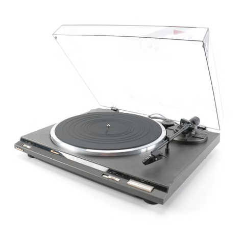
  9. Technics SLD210 User manual

Technics SLD210 User manual

ORDER
NO.
DAD84040075C8
ervice
Manual
Turntable
System
SL-D210Kk)
[E},
[EK],
[XL],
[EG],
*
[EH],
[EF],
[Ei],
[EC],
[XA],
[XM]
Areas
*
[E]
is
available
in
Switzerland
and
Scandinavia.
*
[EK]
is
available
in
United
Kingdom.
*
[XL]
is
available
in
Australia.
*
[EG]
is
available
in
F.R.
Germany.
*
[EB]
is
available
in
Belgium.
*
[EH]
is
available
in
Holland.
*
[EF]
is
available
in
France.
*
[Ei]
is
available
in
Italy.
*
[EC]
is
available
in
Czechoslovakia.
*
[XA]
is
available
in
Southeast
Asia,
Oceania,
Africa,
Middle
Near
East
and
Central
South
America.
*
[XM]
is
available
in
Central
South
America.
(TaD)
is
the
standard
for
plug-in-connector
type.
Products
carrying
this
mark
are
interchangeable
and
adaptable
among
each
other.
*The
color
of
this
model
include
service
and
black.
*
The
black
type
model
is
provided
with
(K)
in
the
Service
Manual.
English
og
H
Specifications
are
subject
to
change
without
notice
for
further
improvement.
Specifications
Weight
and
dimensions
shown
are
approximate.
*This
rating
refers
to
turntable
assembly
alone,
excluding
effects
of
record,
cartridge
or
tonearm,
but
including
platter.
Measured
by
obtaining
signal
from
built-in
frequency
generator
of
motor
assembly.
Rumble:
—56
dB
(IEC
98A
Unweighted)
—
78
dB
(IEC
98A
Weighted)
@
General
Power
supply:
~
240
V,
50
Hz
Power
consumption:
4w
Dimensions:
43x
1037.5
cm
(WxHxD)
(16-15/16"
x3-15/16"
x
14-3/4”)
Maximum
height
when
top
(dust
cover)
is
open.
433741
cm
(16-15/16"
x
14-9/16"
x
16-
1/8")
Weight:
4.4
kg
(9.7
|b.)
@
Tonearm
section
Type:
Statically-balanced
straight
tonearm
Plug-in
connector
cartridge
system
230
mm
(9-1/16'')
15
mm
(19/32"’)
Within
2°32’
at
the
outer
groove
of
30
cm
(12"')
record
Within
0°32’
at
the
inner
groove
of
30
cm
(12"')
record
7.5
g
(without
cartridge)
13.5
g
(including cartridge)
@
Turntable
section
Type:
Direct
drive
Automatic
turntable
Auto
return
Auto
stop
Direct
drive
Brushless
DC
motor
Aluminum
die-cast
Diameter
31.2cm
33-1/3
rpm
and
45
rpm
0.012%
WRMS*
0.025%
WRMS
(JIS
C5521)
+0.035%
peak
(IEC
98A
Weighted)
Effective
length:
Overhang:
Tracking
error
angle:
Drive
method:
Motor:
Turntable
platter:
Seti
Turntable
speeds:
Wow
and
flutter:
Applicable
cartridge
weight:
6g
Matsushita
Electric
Trading
Co.,
Ltd.
PO.
Box
288,
Central
Osaka
Japan
Technics
@
Cartridge
section
Type:
Magnetic
circuit:
Frequency
response:
Output
voltage:
Moving
magnet
stereo
cartridge
All
laminated
core
10
Hz~35
kHz
20
Hz~10
kHz
+1
dB
2.5mV
at
1kHz5cm/s.
zero
to
peak
lateral
velocity
(7
mV
at
1
kHz,
10
cm/s.
zero
to
peak
45°
velocity
[DIN
45
500])
Channel
separation:
Channel
balance:
Recommended
load
impedance:
Compliance
(dynamic):
Stylus
pressure
range:
Weight:
Replacement
stylus:
22
dB
at
1
kHz
Within
2
dB
at
1
kHz
47
kN~100
kN
12x
10-&
cm/dyne
at
100
Hz
1.25+0.25g
(12.5+2.5
mN)
6
g
(cartridge
only)
EPS-27CS
The
power
supply
for
this
unit
varies
depending
upon
the
areas.
Also,
the
parts
used
for
power
supply
are
different.
So,
refer
to
the
circuit
diagram
and
the
replacement
parts
list.
*
220V
(50/60
Hz)
for
Continental
Europe.
240V
(50/60
Hz)
for
United
Kongdom
and
Australia.
110V-120V/220V-240V
(50/60
Hz)
for
other
areas.
[XA]
and
[XM]
areas
are
provided
with
voltage
selector.
Deutsh
TECHNISCHE
DATEN
@
Allgemeine
Daten
Stromversorgung:
Leistungsaufnahme:
Abmessungen:
(Bx
Hx
T)
Gewicht:
@
Plattenspieler
Typ:
Antrieb:
Motor:
Plattenteller:
Plattenteller-Drehzahlen:
Gleichlaufschwankungen:
~220V,
50
Hz
4w
43
x
10
x
37,5cm
Maximale
Hohe
bei
gedffnetem
Oberteil
(Staubabdeck
ung)
:
43
x
37
x
41
cm
4,4
kg
Direktantrieb
Automatischer
Plattenspieler
Rick
fiihrautomatik
Stopautomatik
Direktantrieb
Kollektorloser
Gleichstrommotor
Aluminium-Spritzgu®
Durchmesser
31,2
cm
33-1/3
und
45
U/min
0,012%
WRMS*
0,025%
WRMS
(JIS
C5521)
+
0.035%
Spitze
(IEC
98A
bewertet)
Diese
Nennleistung
bezieht
sich
auf
das
laufwerk-Bauteil
allein,
ausschlieRlich
Ejinfliisse
von
Schallplatte,
Tonab-
nehmer
oder
Tonarm,
aber
einschlieBlich
Plattenteller.
Gemessen
anhand
von
Signalen
vom
eingebauten
Fre-
quenzgenerator
des
Motorbauteils.
Rumpeln:
—56
dB
(IEC
98A
unbewertet)
—78
dB
(IEC
98A
bewertet)
Anderungen
der
technischen
Daten
vorbehalten.
Die
angegebenen
Gewichts-
und
Abmessungsdaten
sind
ungefahre
Werte.
@
Tonarm
Typ:
Effektive
Lange:
Uberhang:
Spurfehlwinkel:
Effektive
Masse:
Auflagekraft-
Einstellbereich:
Zulassiger
Ton-
abnehmergewicht:
@
Tonabnehmer
Typ:
Magnetkreis:
Frequenzgang:
Ausgangsspannung:
Kanaltrennung:
Kanalabweichung:
Empfohlene
Endimpedanz:
Nachgiebigkeit
(dynamisch)
:
Auflagekraft-
Einstellbereich:
Gewicht:
Ersatznadel:
Statisch
balancierter,
gerador
Tonarm
Tonabnehmersystem
vom
Einsteck-Typ
230
mm
15
mm
2°32’
bei
der
Einlaufrille
einer
30
cm-Platte
0°32’
bei
der
Auslaufrille
einer
30
cm-Platte
13,5
g
(einschlieRlich
Tonabnehmer)
1,25+
0,259
6g
Beweglicher
Magnet-Stereo-T
onabnehmer
Genzlamellenkern
10
Hz
bis
35
kHz
20
Hz
bis
10
kHz+
1
dB
2,5
mV
bei
1
kHz
5
cm/s.
Null-zu-Spitze,
lateral
[7
mV
bei
1
kHz
10
cm/s.
Null-zu-Spitex,
45°
(DIN
45
500)
]
22
dB
bei
1
kHz
Innerhalb
2
dB
bei
1
kHz
47
kQ
~100
kQ
12
x
10°
cm/dyn
bei
100
Hz
1,254
0.259
(12,5+
2,5
mN)
6g
(nur
Tonabnehmer)
EPS-27CS
Anderungen
der
technischen
Daten
vorbehalten.
Die
angegebenen
Gewichts-
und
Abmessungsdaten
sind
ungefahre
Werte.
SL-D210
Francais
CARACTERISTIQUES
Le
poids
et
les
dimensions
sonnés
sont
approximatifs.
@
Bras
de
lecture
Type:
@
Géneéralités
Alimentation:
Consommation:
Dimensions:
(Lx
Hx
P)
~220
V,
50
Hz
4W
43x
10x37,5
cm
Hauteur
maximum
lorsque
le
dessus
(couvercie
protege-poussiére)
est
ouvert.
43x37*41
cm
4,4
kg
Longueur
effective:
Porte-a-faux:
Poids:
@
Platine
de
lecture
Type:
Entrainement
direct
Masse
réelle:
Platine
automatique
Retour
automatique
Arrét
automatique
Poids
des
cellules
pick-up
utilisables:
Systeme
d’entraine-
ment:
Moteur:
Plateau
de
lecture:
Entrainement
direct
Moteur
C.C.
sans
balai
En
aluminium
moulé
sous
pression
Diamétre
31,2cm
33-1/3
et
45
t/p.m
@
Cellule
pick-up
Type:
Circuit
magnétique:
Vitesses
de
rotation:
Réponse
en
fréquence:
Pleurage
et
scintille-
ment:
0,012%
de
valeur
efficace*
0,025%
de
valeur
efficace
(JIC
C5521)
+0,035%
de
créte
(IEC
98A
Pondére)
*Ce
régime
nominal
se
rapporte
a
|’ensemble
du
tourne-
disque
seul,
excluant
les
effets
du
disque,
de
la
cellule
pick-up
ou
du
bras
de
lecture,
mais
comprenant
le
plateau,
Mesuré
par
!'obtention
d'un
signal
provenant
du
générateur
de
fréquences
incorporé
de
!’ensemble
du
moteur.
Ronflement:
Tension
de
sortie:
Séparation
des
canaux:
Equilibrage
des
canaux:
Impédance
de
charge
recommandeée:
Elasticité
(dynamique):
Plage
de
la
force
verticale
d’appui:
Poids:
Pointe
de
lecture
de
remplacement:
—
56
dB
(IEC
98A Non
pondéré)
—
78
dB
(IEC
98A
Pondéreé)
Les
spécificatidns
sont
susceptibles
d’étre
modifiées
sans
préavis.
Bras
de
lecture
rectiligne
statiquement
équilibre.
Systeme
de
cellule
de
lecture
a
connecteur
enfichable.
230
mm
15mm
Angle
d’erreur
de
piste:
En
deca
de
2°32’
au
sillon
extérieur
d’un
disque
de
30
cm
En
decga
de
0°32’
au
sillon
intérieur
d’un
disque
de 30
cm
13,5
g
(y
compris
la
cellule
pick-
up)
6g
Cellule
pick-up
stéréo
a
aimant
mobile
Noyau
entiérement
feuilleté
10
Hz
a
35
kHz
20
Hz
a
10
kHz
+1
dB
2,5mV
a1kHz;
5cm/s.,
zéroa
vitesse
latérale
de
créte
(7
mV
a1
kHz,
10
cm/s.,
zéro
a
vitesse
45°
de
créte
[DIN
45
500])
22
dB
a
1kHz
En
deca
de
2dB
a1
kHz
47
kQ~100
kQ
12x
10°§
cm/dyne
a
100
Hz
1,25+0,25g
(12,5+2,5mN)
6
g
(cellule
seule)
EPS-27CS
Espanol
ESPECIFICACIONES
@
En
general
Alimentacion
de
corriente:
Consumo
de
corriente:
Dimensiones:
(Ancho
x
Alto
x
Prof.)
Peso:
El
peso
y
las
dimensiones
indicados
son
apromimados.
C.A,
de
~
220
V,
50
Hz
4W
43
x
10x
37,5cm
(Altura
maxima
cuando
la
parte
de
arriba
(tapa
contra
el
polvo)
esta
abierta.
43
x
37
x
41
cm
44kg
@Seccion
del
plato
giratorio
Tipo:
Método
de
accionamiento:
Motor:
Método
de
control
directo:
Platillo
del
plato
giratorio:
Velocidades
del
plato
giratorio:
Ululaciones
y
trémolo:
Accionamiento
directo
Plato
giratorio
automatico
Retorno
automatico
Parada
automatica
Accionamiento
directo
Motor
de
corriente
continua
sin
escobillas
Control
con
sincronizacion
de
Pase
por
cuarzo
Aluminio
fundido
Diametro
31,2
cm
33-1/3
y
45
rpm
0,012%
WRMS*
0,025%
WRMS
(JIS
C5521)
+
0.035%
cresta
(IEC
98A
Ponderado)
Estas
caracteristicas
se
refieren
Unicamente
al
conjunto
del
plato
giratorio,
con
exclusién
de
los
efectos
porvenientes
del
disco,
cartucho
o
del
brazo
sonoro,
incluyendo,
empero,
el
platillo.
La
medida
fue
tomada
por
medio
de
Ia
sefial
obtenida
del
generador
de
frecuencia
incorporado
del
conjunto
del
motor.
Ruido
de
rodadura:
—56
dB
(IEC
98
No
Ponderado)
—78
dB
(IEC
98A
Ponderado)
Las
especificaciones
quedan
sujetas
a
cambios
sin
aviso
previo.
@
Seccion
del
brazo
sonoro
Tipo:
Longitud
efectiva:
Proyecci6on:
Angulo
de
error
de
seguimiento:
Masa
efectiva:
Radio
de
ajuste
de
la
presién
de
la
aguja:
Radio
de
peso
de
cartucho
utilizable:
@
Seccion
de
cartucho
Tipo:
Circuito
magnético:
Respuesta
de
frecuencia:
Voltaje
de
salida:
Separachén
de
canales:
Equilibrio
de
canales:
Impedancia
de
carga
recomendada:
Elasticidad
(dindmica):
Radio
de
presion
de
la
aguja:
Peso:
Aguja
de
racambio:
Brazo
sonoro
recto
equilibrado
estaticamente
Sistema
de
cartucho
con
conector
enchufable
230
mm
15mm
Inferior
a
2°32’
en
el
surco
exterior
de
un
disco
de
30
cm
Inferior
a
0°32’
en
el
surco
interior
de
un
disco
de
30
cm
13,5
g
(incluyendo
el
cartucho)
1,254
0,259
6g
Cartucho
estereofonico
de
iman
movil
Nucleo
totalemente
laminado
10
Hza
35
kHz
20
Hza
10
kHz+
1dB
2,55mVaikHz
Con
velocidad
lateral
de
cero
a
cresta
de
5
cm/s.
[7
mV
a1
kHz
Velocidad
de
45°
de
cero
a
cresta
de
10
cm/s.
(DIN
45
500)]
22
dBa1
kHz
Sin
exceder
2dBa
1
kHz
47
kQa
100k
12
x
10°©
cm/dina
a
100
Hz
1,25+0,25
9
(12,5
+
2,5
mN)
6
g
(cartucho
sdlo)
EPS-27CS
Las
especificaciones
quedan
sujetas
a
cambios
sin
aviso
previo.
EI
peso
y
las
dimensiones
indicados
son
aproximados.
m@
CONTENTS
Page
Page
LOCATION
OF
CONTROLS.........
eee
ee
eee
eee
5
TROUBLE
SHOOTING
.......
0.00.0.
e
eee
teense
10
DISASSEMBLY
INSTRUCTIONS
..........---+2-2055
6
SCHEMATIC
DIAGRAM
.... 0...
00.
ee
ees
11
MEASUREMENTS
AND
ADJUSTMENT
(English)
.........
8
CIRCUIT
BOARD
AND
CONNECTION
MESSUNGEN
UND
JUSTIERUNGEN
(Deutsh)...........
8
WIRING
CONNECTION
DIAGRAM
..............
12
MESURAGES
ET
REGLAGES
(Frangais)..
2...
...0-0
0005
9
EXPLODED
VIEWS
...
1...
ce
ee
ee
et
14
MEDICIONES
Y
AJUSTE
(Espafiol)...............2.24-
9
REPLACEMENT
PARTS
LIST.
...........0..200
56
17
BLOCK
DIAGRAM.
..........
000
eee
eee
ee
eee
10
PACKING:
5.:3-c5:
ar
ec
eg
oe
ee
aed
Beas
Sele
Paes
18
m
LOCATION
OF
CONTROLS
|
45-rpm
sso.
$$
Turntable
mat
Arm
clamp
Center
spindle
Arm
reset
a
Tonearm
}
Turntable
platter
Speed
selector
OE
Stop
Cueing
control
SL-D210
m@
DISASSEMBLY
INSTRUCTIONS
e@
How
to
remove
the
cartridge
1.
Open
the
dust
cover.
How
to
remove
the
bottom
board
.
Clamp
the
tonearm
to
the
arm
rest.
2.
Clamp
the
tonearm
to
the
arm
rest.
.
Remove
the
turntable
platter,
and
close
the
dust
cover.
3.
Remove
the
cartridge
setscrew
(Fig.
1
:
@),
and
then
.
Turn
over
the
unit
on
a
soft
cloth
taking
care
not
to
pul!
out
the
cartridge
in
the
direction
of
the
arrow.
damage
the
cabinet
and
dust
cover.
.
Remove
the
5
setscrews
(Fig.
2:
@
~@)
of
the
bottom
board.
Please
note
that
the
front
and
rear
insulators
are
different
from
each
other.
Wn
@
Cartridge
Front
22
mm———
Brown
(Dark)
Rear
L-—225
OO]
Fig.
2
Soft
corth
Brown
(Light)
e
How
to
remove
the
automatic
mechanism
plate
1.
Move
the
cueing
control
knob
to
‘‘cueing
down”
position.
2.
Remove
the
bottom
board.
(Refer
to
‘How
to
remove
the
bottom
board.’’)
3.
Remove
the
7
setscrews
(Fig.
3:
@
~
@)
of
the
automatic
mechanism
plate.
4.
Remove
the
stop
rod,
and
lift
the
automatic
mechanism
plate.
(Fig.
3)
*
When
fitting
the
automatic
mechanism
plate,
check
the
following
points.
(1)
Turn
the
main
gear
until
it
comes
to
the
no
gear
part.
(2)
Shift
the
cueing
lever
plate
in
the
direction
of
the
arrow.
(Fig.
3)
Stop
rod
Cueing
lever
plate
Automatic
mechanism
plate
Fig.
3
No
gear
part
—
6
—
How
to
remove
the
stator
frame
1.
Remove
the
automatic
mechansim
plate.
(Refer
to
“How
to
remove
the
automatic
mechanism
plate.’’)
.
Remove
the
4
setscrews
(Fig.
4:
@
~
@)
of
the
stator
frame.
.
Remove
the
stator
frame
from
the
2
claws
in
the
direction
of
the
arrow.
(Fig.
4)
How
to
remove
the
PU
fixing
plate
1.
Remove
the
automatic
mechanism
plate.
(Refer
to
“‘How
to
remove
the
automatic
mechanism
plate.’’)
.
Remove
the
PU
fixing
plate
setscrew
(Fig.5:
@®
).
Then
the
PU
fixing
plate
can
be
removed.
How
to
remove
the
tonearm
1.
Remove
the
PU
fixing
plate.
(Refer
to
“How
to
remove
the
PU
fixing
plate.’’)
2.
Remove
the
shield
plate.
(Fig.
5)
3.
Unsolder
the
5
lead
wires
of
the
phono
output
terminal.
(Fig.
5)
4.
Remove
the
tonearm
setscrews
(Fig.
5:
@,
@
).
Then
the
tonearm
can
be
removed.
e
How
to
remove
the
lift
base
and
arm
lift
1.
Remove
the
tonearm.
(Refer
to
“How
to
remove
the
tonearm”.)
2.
Remove
the
2
setscrews
(Fig.
6
:
@
,
@
)
of
the
lift
base.
Then
the
lift
base
can
be
removed.
3.
Remove
the
screw
(Fig.
6
:
@
)
of
the
arm
lift.
Then
the
arm
lift
can
be
removed.
e
How
to
remove
the
Hall
element
1.
Remove
the
turntable
platter.
2.
Remove
the
terminal
solder
by
use
of
solder
sucker,
3.
Hold
the
Hall
element
with
a
tweezers
and
remove
it
while
touching
the
soldering
iron
to
the
terminal.
(Fig.
7)
Note:
Fit
the
Hall
element
with
the
part
No,
print
up.
The
reverse
in
terminal
position
is
allowable
provided
that
the
printed
side
is
up.
Fig.
7
Stator
frame
PU.
fixing
plate
Canceller
spring
Shield
plate
Lead
wires
White
L
channel
(+)
Blue
L
channel
(—)
Red
R
channel
(+)
:
Green
R
channel
(—)
Fig.5
~—
Black
Ground
(Earth)
Tweezers
Lift
base
Hall
elements
Arm
tift
SL-D210
m
MEASUREMENTS
AND
ADJUSTMENT
1.
Arm-lift
height
English
ssceeeen
The
arm-lift
height
(distance
between
the
stylus
tip
and
the
record
4mm
~
6
mm
(5/32”
~
1/4”)
surface
when
the
cueing
control
is
at
the
‘’
W
”
position)
has
been
adjusted
at
the
factory
to
aproximately
4
to
6
mm
(5/32”
~
1/4”).
If
the
clearance
is
too
narrow
or
too
wide,
turn
the
adjustment
screw
clockwise
or
counterclockwise.
Clockwise
rotation
—
distance
between
the
record
and
stylus
tip
is
decreased.
Counterclockwise
rotation
—
distance
between
the
record
and
stylus
tip
is
increased.
Adjustment
screw
2.
Automatic
return
position
(Remove
the
rubber
cap.)
1.
Put
the
stylus
protector
on
the
cartridge.
Rubber
cap
2.
Move
the
tonearm
toward
the
center
of
the
record.
The
auto-return
adjustment
screw
will
appear.
~
If
the
tonearm
tends
to
return
to
the
arm
reset
before
the
play
has
AN
finished.
Auto-return
‘
adjustment
screw
—
turn
counterclockwise.
If
the
tonearm
fails
to
return
after
the
final
groove.
—
turn
clockwise.
mM
MESSUNGEN
UND
JUSTIERUNGEN
=o
2)
Ut
SC)
se
1.
Justierung
der
Tonamlifthod
he
Die
Tonarmilifthohe,
d.h.
der
Abstand
zwischen
Nadelspitze
und
Schaliplattenoberflache
bei
Liftsteuerungs-Position
‘“
¥
,
wurde
werkseitig
auf
ca.
4
~
6
mm
eingstellt.
Falls
der
Abstand
zu
gro&
oder
zu
klein
ist
(z.B.
wegen
unterschiedlicher
TonabnehmergrdBe),
drehen
Sie die
Justierschraube
im
Uhrzeigersinn
oder
entgegen
dem
Uhrzeigersinn.
Drehung
im
Uhrzeigersinn
—
Der
Abstand
zwischen
der
Platte
und
der
Nadelspitze
wird
kleiner.
Drehung
entgegen
dem
Uhrzeigersinn
—
Der
Abstand
zwischen
der
Platte
und
der
Nadelspitze
wird
gréRer.
Is
Sq
|
Justierschraube
2.
Justierung
des
Abschaltpunktes
der
Automatik
(Die
Gummikappe
abnehmen)
1,
Setzen
Sie
den
Nadelschutz
auf
den
Tonabnehmer
auf.
Gummikappe
2.
Fuhren
Sie
den
Tonarm
gegen
die
Plattenmitte.
Die
Justierschraube
fiir
den
Abschaltpunkt
der
Automatik
wird
dann
sichtbar.
aN
Falis
der
Tonarm
zu
frish
zuriickkehrt.
Abschaltpunkt-
—
Entgegen
dem
Uhrzeigersinn
drehen.
austere.
Falls
der
Tonarm
nach
Erreichen
der
Auslaufrille
nicht
zuriickkehrt.
—
Im
Uhrzeigersinn
drehen.
m
MESURAGES
ET
REGLAGES
1.
Mise
au
point
de
la
hauteur
de
I’élévateur
du
bras
La
hauteur
de
l’élévateur
du
bras
(distance
entre
l’extrémité
de
la
pointe
de
lecture
et
la
surface
du
disque,
lorsque
la
commande
de
pose
et
de
relevage
est
a
la
position
“’
VW
”)
a
été
réglée
en
usine
sur
approximativement
4
a
6
mm.
Si
l’écartement
est
trop
étroit
ou
trop
large,
tourner
la
vis
de
réglage
dans
le
sens
des
aiguilles
d’une
montre
ou
dans
le
sens
contraire.
Rotation
dans
le
sens
des
aiguilles
d’une
montre.
—
La
distance
entre
la
surface
du
disque
et
l’extrémité
de
la
pointe
de
lecture
diminue.
Rotation
dans
le
sens
contraire
des
aiguilles
d'une
montre.
—
La
distance
entre
la
surface
du
disque
et
l’extrémité
de
la
pointe
de
lecture
augmente.
Vis
de
réglage
2.
Mise
au
point
de
la
position
de
retour
automatique
(Retirer
le
tapis
du
plateau
de
lecture.)
1.
Placer
le
capot
protecteur
de
la
pointe
de
lecture
sur
la
cellule
pick-up.
2.
Déplacer
le
bras
de
lecture
vers
le
centre
du
disque.
Alors,
la
vis
de
réglage
du
retour
automatique
apparaitra.
Si
le
bras
de
lecture
tend
a
revenir
vers
le
support
du
bras
avant
que
Vis
de
soled
du
‘audition
ne
soit
terminée.
retour
automatique
—
tourner
dans
le
sens
contraire
des
aiguilles
d‘une
montre.
Si
le
bras
de
lecture
ne
peut
revenir
en
arriére
aprés
le
dernier
sillon.
--
tourner
dans
le
sens
des
aiguilles
d’une
montre.
Capuchon
caoutchouté
1.
Ajuste
de
la
altura
de
elevacion
del
brazo
La
altura
de
elevacion
del
brazo
(0
sea,
la
distancia
entre
la
punta
de
la
aguja
y
la
superficie
del
disco
cuando
el
control
de
colocacion
esté
en
la
posici6n
“
VW
")
has
sido
regulada
en
la
fabrica
aproximadamente
entre
4
y
6mm.
En
caso
que
la
distancia
fuese
demasiado
abundante
o
demasiado
escasa,
girar
el
tornillo
de
ajuste
hacia
la
derecha
o
hacia
la
izquierda.
Rotaci6on
hacia
la
derecha
—
reduce
la
distancia
entre
el
disco
y
la
punta
de
la
aguja.
Rotaci6dn
hacia
la
izquierda
—
aumenta
la
distancia
entre
el
disco
y
la
punta
de
la
aguja.
Tornillo
de
ajuste
2.
Ajuste
de
la
posicién
para
retorno
automatico
(Quitar
la
almohadilla
del
plato
giratorio.)
1.
Colocar
la
proteccién
de
la
aguja
en
el
cartucho.
2.
Mover
el
brazo
sonoro
hacia
el
centro
del
disco.
Con
ello,
aparecera
el
tonillo
de
ajuste
del
retorno
automatico.
Cuando
el
brazo
sonoro
tienda
a
volver
a
su
apoyo
antes
de
terminar
|
.
os
=
.
a
ejecucion.
Tornillo
de
ajuste
de
—
Girar
hacia
la
izquierda.
retorno
automatico
En
caso
que
el
brazo
sonoro
no
vuelva
después
de
haber
tocado
el
Ultimo
surco
del
disco.
—
Girar
hacia
la
derecha.
Tapdén
de
goma
SL-D210
m@
BLOCK
DIAGRAM
AN6339
X101
Counter
|
52416kHzE5
13
Counter
2
tev
-
Speed
select
Drive
coil
7
=
emi
Two
phase
9
full
wave
drive
circuit
om
C5
3
af
6
12
16
lev
334
945
$2
SELECTOR
icl
DI
$s!
TI
ON:
OFF
_
eae
: ‘
C
ie
m
TROUBLE
SHOOTING
@
Power
source
circuit
DC
voltage
of
1C101
pin
43)
——
11.8V
T1,$1
D1,
1C1,
1€101
Turntable
does
not
rotate
Drive
coil
and
Hall
element
.
: :
Drive
coil
.
Conduction
check
of
drive
coils
(A1
~
A4)
H101.
H102
2.
DC
voltage
of
Hall
elements
(H101,
H102)
IC101
Refer
to
schematic
diagram
®
Oscillator
circuit
Waveforms
of
pins
@
and
@
of
IC101
Refer
to
schematic
diagram
Untable
rotation
Turntable
drive
circuit
.
DC
voltage
of
pins
@),
42,
and
45)
of
1C101
Refer
to
schematic
diagram
2.
Waveforms
of
pins
(%)
~
of
[C101
Refer
to
schematic
diagram
@
Speed
selector
circuit
DC
voltage
of
pin
@®
of
1C101
33
rpm
1.4V
45
rpm
OV
Speed
cannot
be
changed
a
2
P
m@
SCHEMATIC
DIAGRAM
(This
schematic
diagram
may
be
modified
at
any
time
with
development
of
new
technology.)
1.
$1
:
On/off
(power)
switch
in
‘‘on”
position.
5.
2.
$2
:
Speed
selector
switch
in
‘‘33
rpm”
position.
6.
3.
$901
:
Voltage
selector
switch
in
‘’110-120V"
position.
4.
The
voltage
value,
and
waveforms
are
the
reference
voltage
values
of
this
unit
measured
by
DC
electronic
voltmeter
(high
impedance)
and
oscilloscope
on
the
basis
of
chassis
when
the
unit
is
in
play.
Notes:
c2
0.022
0.022
c3
AC
220V
(50/60Hz)
aes
continenta
y
Europe
AC
240V
(50/60Hz)
For
United
Kingdom
and
Austraria
C10!
AN6639
«Between
Aland
A2
e
Between
A3
and
A4
1
2
3
DI
SVDSIWB40
RECTIFIER
TURNTABLE
DRIVE
+B
voltage
lines.
Important
safety
notice:
Components
identifier
by
A\
mark
have
special
character-
istics
important
for
safety.
When
replacing
any
of
these
components,
use
only
manufacturer's
specified
parts.
4
5
iC|
AN78Ml2
REGULATOR
SPEED
SELECTOR
33
33rpm
—
299
~30Imsec.
45rpm—
221
~223msec.
e
Between
HI
and
HIB
e
Between
H2
and
H2B
33
rpm
—
299~301
msec.
45rpm
—
221
~223
msec.
S22
~
S26kHz
Wie
r
IV
522
~
526kHz
HIO1,
102
OH-003
—i1—
HALL
ELEMENT
m@
CIRCUIT
BOARD
AND
WIRING
CONNECTION
DIAGRAM
e
Power
source
circuit
For
[XA]
and
[XM]
areas
Note:
AC
220V
(50/60
Hz)
(For
continental
Europe)
AC
240V(50/60H2)
AC
|110-120/220-240vV
(
50/60Hz)
To
FC5
terminal
(T1)
Power
transformer
Voltage
selector
For
the
performance
improvement
of
this
unit,
the
turntable
drive
circuit
is
changed
during
production.
When
calling
for
service,
please
carefully
read
the
information
below.
Serial
No.
sheet
change
mark
after
Serial
No.
sheet
change
mark
Serial
No.
sheet
change
mark
[E]
ERDI0TLJ822U
=
(8.2k)
ERDI0OTLJ103U
=
(10k)
ERDIOTLJ822U
=
(8.2k)
ECEA1AN470S
(47uF)
C107
ECEA1CN100S
(10uF)
ECEA25N4R7
(4.7uF)
ECEA1AN330S
(33uF)
ECEA1AN330S
(33uF)
ECEA1CN100S
(10uF)
Power
transformer
(For
United
kingdom
and
Austraria)
TI
ON-OFF
switch
S|
SPEED
SELECTOR
m
CIRCUIT
BOARD
AND
WIRING
CONNECTION
DIAGRAM
e@
Power
source
circuit
For
[XA]
and
[XM]
areas
ave
special
character-
placing
any
of
these
oe
AC
220V
(50/60
Hz)
pecified
parts.
(For
continental
Europe)
VOLTAGE
a
|
SELECTOR
rower
|
transformer
i
5
AC
240V(50/60H2)
(For
United
kingdom
and
Austraria)
1cl
AN78Ml2
REGULATOR
AC
'lO-l20/220-
240V
(
50/60
Hz)
To
FC5
terminal
AC
socket
45
————
33
Voltage
selector
SPEED
SELECTOR
Note:
For
the
performance
improvement
of
this
unit,
the
turntable
drive
circuit
is
changed
during
production.
When
calling
for
service,
please
carefully
read
the
information
below.
Serial
No.
sheet
Serial
No.
sheet
Serial
No.
sheet
change
mark
[E]
change
mark
change
mark
after
[G]
ERDIOTLJ822U
=
(8.2k)
ERDIOTLJ103U
=
(10k)
ERDI0TLJ822U
=
(8.2k)
ECEA1AN470S
(47uF)
ECEA1AN330S
(33uF)
ECEA1AN330S
(33uF)
ECEA1CN100S
(10uF)
ECEA25N4R7
(4.7
uF)
ECEA1CN100S
(10uF)
SL-D210
SL-D210
m
EXPLODED
VIEWS
e
Automatic
me
e
Cabinet
and
Chassis
Parts
Automatic
Mechnism
Plate
Ass’y
a)
a
ee)
oa
[0]
e
Automatic
mechanism
plate
parts
m@
REPLACEMENT
PARTS
LIST
Notes:
1.
Please
use
this
part
number
for
parts
orders.
2.
Important
safety
notice:
Part
numbers
are
indicated
on
most
mechanical
parts.
Components
identified
by
A\
mark
have
special
characteristics
important
for
safety.
When
replacing
any
of
these
components,
use
only
manufacturer's
specified
parts.
Bracketed
indications
in
Ref.
No.
columns
specify
the
area.
Parts
without
these
indications
can
be
used
for
all
areas.
production
parts.
for
the
quantity
per
set.
parts
are
for
silver
type
only.
Ref.
No.
Part
No.
Description
The
"6"
mark
is
service
standard
parts
and
may
differ
from
The
parenthesized
numbers
in
the
column
of
description
stand
®-marked
parts
are
used
for
black
type
only,
while
O-marked
7.
Part
other
than
(K)-and
Omarked
are
used
for
both
black
and
silver
types.
|
Black
type
model
No.
:
SL-D210
(K)
Areas
Description
*
[Ei]
is
available
in
Italy.
*
[EC]
is
available
in
Czechoslovakia.
*
[XA]
is
available
in
Southeast
Asia,
Oceania,
Africa,
Middle
Near
East
and
Central
South
America.
*
[XM]
is
available
in
Central
South
America.
*
[E]
is
available
in
Switzerland
and
Scandinavia.
*
[EK]
is
available
in
United
Kingdom.
*
[XL]
is
available
in
Australia.
*
[EG]
is
available
in
F.R.
Germany.
*
[EB]
is
available
in
Belgium.
*
[EH]
is
available
in
Holland.
*
[EF]
is
available
in
France.
Part
No.
Description
INTEGRATED
CIRCUITS
CABINET
and
CHASSIS
PARTS
SFUPB63M52A
C1
1C101
AN78M12
AN6639
Reguiafor
Turntable
Drive
DIODES
A
D1
D101
SVDS1WB40
MA1075-FV
Rectifier
7.5V
Zener
4(XA.XM)
HALL
ELEMENTS
4(other
H101,102
OH-002
Turntable
Position|}
areas)
Detector
OSCILLATOR
X101
SWITCHES
F902(XA,XM)
only
—
SVFCSB525P
SFDSD72R01
SFDSHSW0739
SFDSHXW225-2
XBA2CO5TRO
XBA2CO016TRO
_L
524.16kHz
Ceramic
Oscillator
Power
Speed
Selector
Voltage
Selector
g(xt)
ZA
9(XA,XM)
ZA
Mother
A
250V,T500mA
areas)
250V,T160mA
POWER
TRANSFORMER
A
A
A
TICEK,XL)
TI{XA,XM]
Tilother
areas)
SLT48DTE13E
SLT57DT7E
SLT48DT10E
Power
Source
Power
Source
Power
Source
RESISTORS
13(EK,XL)
R101
R102
R103
R104
R105
ERD10TLJ101U
ERX1ANJ1R8
ERD10TLJ822U
ERD1OTLJ150U
ERD10TLJ101U
Chip
Carbon,1/8W
1000
,+5%
Metal
Film,1W,
1.80
,+5%
Chip
Carbon,1/8W
8.2kQ
,+5%
Chip
Carbon,1/8W
15Q,+5%
Chip
Carbon,1/8W
1000
,+5%
13
(XA,XM)
13
(Other
CAPACITORS
C1~3
aN
©
ECQM1223KZ
ECEB1VU102
ECFR1H1042F
ECUV1H332JUU
ECUV1H181JCM
ECEA1AN470SB
ECEA1AN330S
ECFRIH104ZF
ECEATCN100S
ECEA1AM330T
ECEA1CU330
Polyester,
100V,
0.022
u
F,+10%
Electrolytic,35V,
1000
2
F
Ceramic,50V,
0.1
pF,
80%
Chip
Ceramic,
§0V,0.0033
uF,
+5%
SFTGZ15R01
SFTEQ72R01A
SFMZQ63M53A
SFGCCO5X01
SFGCCO5N02
SFKKD72R01
SFKKD72R02
SFACD72R01R
SFACD72R21R
SFMGQ34N01
SFOJHSC0491
SFDJHSC04912
SFOJHSC0498
SFADZ15RO1E
SFGZDO4NO01
SFATZ15R01
SFNND72S01
SFNND72G01
SFNND72X01
SFNND72R01
SFDJZ15R01
SFKTZ15R02
SFKTZ15R01
SFQHZ15R01
SFUZ863M01
SFQPZ15R02
SFYB-5-32
SFUPZ15R03
SFKTZ15R04
SFUPZ15R05
SFAUZ15R01
SFGAZ15R01
SFGAQ63M01
SFGZZ15R02
SFGZB63M01
Turntabie
Mat
Turntable
Platter
Ass’y
Stator
Frame
Ass’y
Cushion
Rubber,
Power
Transformer
Cushion
Rubber,
Power
Transformer
Ornament
Plate
Badge
Cabinet
(Silver)
Cabinet
(Black)
Cover,
Stator
Coil
AC
Socket
AC
Socket
AC
Socket
Dust
Cover
Cushion
Rubber,
Dust
Cover
Hinge
Name
Plate
Name
Plate
Name
Plate
Name
Plate
Jack,
Phono
Output
Knob,
Speed
Selector
Button,
Stop
Spring,
Stop
Button
Rod,
Stop
Spring,
Cueing
Knob
Bail
Lever,
Cueing
Knob,
Cueing
Hoider,
Cueing
Knob
Bottom
Board
Audio
Insulator
Audio
Insulator
Hoider,
Lead
Wires
Holder,
Lead
Wires
SFQHB63M56
SFQHB63M57
EPC-P27S
EPS-27CS
SFCNC03301
PU
Fixing
Ass‘y
Spring
Spring,
Antiskating
*
Cartridge
*Stylus
Cover,
Stylus
IC
MECHANISM
PLATE
PARTS
SFUMQ63M51E
SFQHB63M53
SFUMB63M59
SFUMB63M60
SFQPB63M54
SFQPB63M52
SFQHB63M55
SFQSB63M52
SFUZB63M52
SFUMB63M61
SFUMB63M65
SFUBB73R51E
SFUMB63M55E
SFQHB63M52
SFUMB63M53E
SFQHB63M51
SFUGB63M51E
SFQSB63MS1
SFUMB63M54
SFUKB63M51E
SFUMZ15R56
Record
Size
Detector
Ass‘y
Spring,
Record
Size
Detector
Lever,
Cueing
Cam,
Cueing
Spring,
Cueing
Cam
Spring,
Cueing
Can
SPring,
Cueing
Spring,
Brake
Lever
Feit,
Brake
Lever
Lever,
Brake
Guide
Plate,
Tonearm
Drive
Ptate
Ass’y
Lever
Ass’‘y,
Switch
Spring,
Switch
Lever
Lever
Ass’y,
Cancel
Spring,
Cancel
Lever
Main
Gear
Ass’y,
Drive
Rod,
Drive
Lever,
Drive
Base
Ass’y,
Automatic
Mechanism
Pin
SCREWS
and
WASHERS
XTV3+8BFN
XWG3
XWA3B
XSN3+12S
XTV3++6BFN
SFXWCO06N02
XTN3+30J
XTV3-+10BFN
XTW34+14QFYR
SFXGB33N01
XYE3+EJ8
XTS3+16FFZ
SFPEV0Q601
SFXGQ34N02
SFXWZ15R51
SFXWB63M52
Chip
Ceramic,
TONEARM
PARTS
SFUMZ15R61
50V,180pF,+5%
Non
Polar
Elec-
trolytic,10V,47
py
F
Non
Polar
Elec-
{
trolytic,
10V,
334
F
Ceramic,50V,
0.1u
F,
188%
Non
Polar
Elec-
trolytic,16V,10
p
F
Electrolytic,
10V,
33H
F
Electrolytic,
16V,
33uF
O
®
SFPAMQ3207A
SFPAMQ3208A
SFKUZ15R01
SFGK170-01
SFGK171F01
SFKKZ15R01
SFUMZ15R58
SFQAZ15R52
SFUPB63M51A
Tonearm
Ass’y
(Silver)
Tonearm
Ass’y
(Black)
Tonearm
Rest
Rubber
Cap
(Silver)
Rubber
Cap
(Black)
Plate,
Cancelier
Tonearm
Lift
Spring,
Tonearm
Lift
Base,
Tone
Arm
Screw
Washer
Washer
Screw
Screw
Washer
Screw
Screw
Screw
Screw
Screw
Screw
Screw
Screw
Washer
Washer
Washer
SL-D210
m@
PACKINGS
(A3,
A4,
AS)
Ref.
No.
Part
No.
Description
Ref.
No.
Turntable
mat
P12
P13
Part
No.
Description
PACKING
PARTS
ACCESSORIES
A1(EK]
SFNUD72G01
SFNUD72x01
AI(EG)
SFNUD72R01
A1(EF)
SFNUD72F01
AI(E)
SFNUD72101
At
(other
SFNUD72S01
areas}
A2
SFWE212-01
AS(EK)
ZA\|
SFDACOSG02
SFDACOSX02
SFDACOSLO1
SFDACO5E02
A4
SFDHCOS5NO1
AS(XL)
A5(other
areas]
SFDLCO5N01
SFDLZ15R01
AG(XAXM)
A,
only
SFDKI19118
Instruction
Book
instruction
Book
Instruction
Book
Instruction
Book
Instruction
Book
Instruction
Book
45Adaptor
AC
Cord
AC
Cord
AC
Cord
AC
Cord
Phono
Output
Cord
Ground
Wire
Ground
Wire
2pin
plug
P1(EF)
P1
(other
areas)
P1(EF)
P1
(other
areas)
©|
SFHPO72F01
(O|
SFHPD?2R01
Carton
Box
(Silver)
Carton
Box
(Silver)
®
|
SFHPD72F21
®
|
SFHPD72R21
Carton
Box
(Black)
Carton
Box
(Black)
SFHHQ63M01
Pad,
Front
(Left)
SFHHQ63M02
‘|
Pad,
Front
(Right)
SFHHQ63M03
Pad,
Rear
(Left)
SFHHQ63M04
Pad,
Rear
(Right)
SFHZQ62M01
Pad,
Tonearm
SFHZZ15RO02
Stopper,
AC
Cord
SFHZZ15R03
Clamper,
Tonearm
SFHKQ63M01
Clamper,
Turntable
SFHZDO3M01
Sheet,
Dust
Cover
SFYH60X60
Polyethylene
Bag,
Unit&Dust
Cover
Polyethylene
Bag,
Turntable
Mat
Pad,
Turntable
Mat
Polyethylene
Bag,
Cords
Polyethylene
Bag,
45Adaptor
Pad,
Pust
Cover
SFYF30B35
SFHDZ15R01
SFYH18X17
SPJ15
SFHZQ63M01
.
Plase
the
unit
(with
cushions
attached)
as
illustrated.
.
Fold
the
flaps
according
to
the
line
marks.
.
Seal
the
top
with
adhesive
tape.
*
Use
gum
tape
or
adhesive
cloth
tape
of
50mm
wide
at
least
.
For
the
edges,
first
fold
the
flap
‘‘a’’
and
then
flap
“b’’,
and
staple.
Remember
to
staple
only
flap
‘‘b’’.
(Use
15
or
16mm
staple)
P1
Printed
in
Japan
84047000
(H)
TK

This manual suits for next models

12

Other Technics Turntable manuals

Technics SL-1200GR User manual

Technics

Technics SL-1200GR User manual

Technics SL-Q303 User manual

Technics

Technics SL-Q303 User manual

Technics SL-1500C User manual

Technics

Technics SL-1500C User manual
Technics SL-1200G User manual

Technics

Technics SL-1200G User manual

Technics SL-B210 - SERVICE User manual

Technics

Technics SL-B210 - SERVICE User manual

Technics SL-1500 User manual

Technics

Technics SL-1500 User manual

Technics SL1210GREGK User manual

Technics

Technics SL1210GREGK User manual

Technics SL-QL15 User manual

Technics

Technics SL-QL15 User manual

Technics SL-Q2 User manual

Technics

Technics SL-Q2 User manual

Technics SL-DL1 User manual

Technics

Technics SL-DL1 User manual

Technics SL-1200M3D User manual

Technics

Technics SL-1200M3D User manual

Technics SL-1200MK2 User manual

Technics

Technics SL-1200MK2 User manual

Technics SL-1200GR User manual

Technics

Technics SL-1200GR User manual

Technics SL-1100A User manual

Technics

Technics SL-1100A User manual

Technics SL-100C User manual

Technics

Technics SL-100C User manual
Technics SL-DZ1200PP User manual

Technics

Technics SL-DZ1200PP User manual

Technics SL-QL1 User manual

Technics

Technics SL-QL1 User manual

Technics SL-1200MK2 Operating manual

Technics

Technics SL-1200MK2 Operating manual

Technics SL-1500C User manual

Technics

Technics SL-1500C User manual

Technics SL-J110R User manual

Technics

Technics SL-J110R User manual

Technics SL-DL1 User manual

Technics

Technics SL-DL1 User manual

Technics SL-J300R User manual

Technics

Technics SL-J300R User manual
Technics SL-DZ1200PP User manual

Technics

Technics SL-DZ1200PP User manual

Technics SL-1200LTD User manual

Technics

Technics SL-1200LTD User manual

Popular Turntable manuals by other brands

Conrad DJ-Tech Vinyl Encoder 5 user manual

Conrad

Conrad DJ-Tech Vinyl Encoder 5 user manual

Pioneer PL-A45D Service manual

Pioneer

Pioneer PL-A45D Service manual

Victrola VTA-245B instruction manual

Victrola

Victrola VTA-245B instruction manual

Pioneer PL-30-K operating instructions

Pioneer

Pioneer PL-30-K operating instructions

Garrard 301 user manual

Garrard

Garrard 301 user manual

SOUNDMASTER PL585 instruction manual

SOUNDMASTER

SOUNDMASTER PL585 instruction manual

camry CR 1149 user manual

camry

camry CR 1149 user manual

Pro-Ject Audio Systems 2 Xperience Basic + Instructions for use

Pro-Ject Audio Systems

Pro-Ject Audio Systems 2 Xperience Basic + Instructions for use

ION Bronco LP quick start guide

ION

ION Bronco LP quick start guide

Pro-Ject Audio Systems Pro-Ject 6 PerspeX Instructions for use

Pro-Ject Audio Systems

Pro-Ject Audio Systems Pro-Ject 6 PerspeX Instructions for use

Teac TTD109SP quick start guide

Teac

Teac TTD109SP quick start guide

Elta 2957 instruction manual

Elta

Elta 2957 instruction manual

Stanton T.52 user manual

Stanton

Stanton T.52 user manual

Kuzma Stabi S12 instruction manual

Kuzma

Kuzma Stabi S12 instruction manual

Pro-Ject Audio Systems RPM 6.1 SB SuperPack Instructions for use

Pro-Ject Audio Systems

Pro-Ject Audio Systems RPM 6.1 SB SuperPack Instructions for use

Vestax PDX-2000 owner's manual

Vestax

Vestax PDX-2000 owner's manual

Pioneer QuartzPLL PL-540 Service manual

Pioneer

Pioneer QuartzPLL PL-540 Service manual

Pro-Ject Audio Systems Pro-Ject RPM 1.3 Genie Instructions for use

Pro-Ject Audio Systems

Pro-Ject Audio Systems Pro-Ject RPM 1.3 Genie Instructions for use

manuals.online logo
manuals.online logoBrands
  • About & Mission
  • Contact us
  • Privacy Policy
  • Terms and Conditions

Copyright 2025 Manuals.Online. All Rights Reserved.