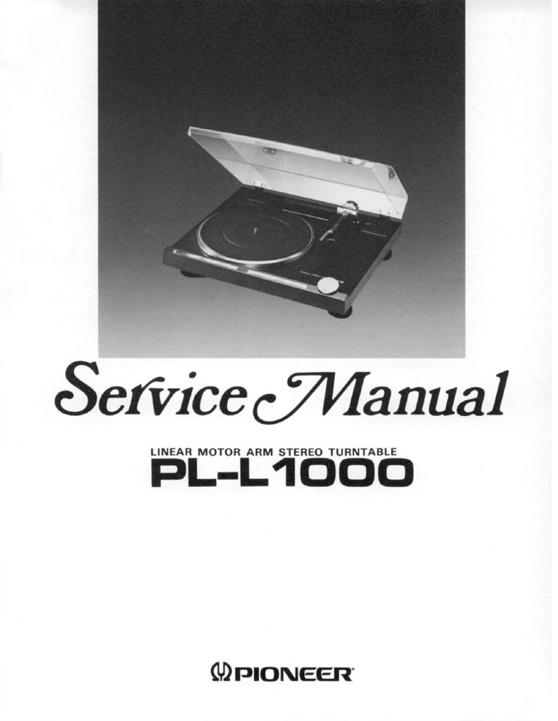
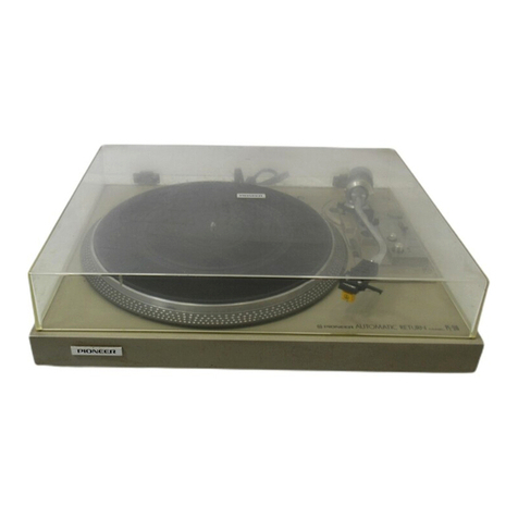
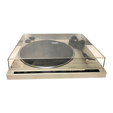
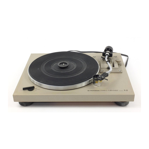
Pioneer QuartzPLL PL-540 User manual

saan
sia
an
OH
c/Mlanual
Service
zPLL
DIRECT
DRIVE
STEREO
TURNTABLE
“te
ar
Qu
2
O
a
=

120V
only
120V
only
220V
and
240V
(switchable)
110V,
120V,
220V
and
240V
(switchable)
110V,
120V,
220V
and
240V
(switchable)
Canada
model
(without
cartridge)
U.S.A.
model
(without
cartridge)
Europe
or
Oceania
model
(without
cartridge)
General
export
model
(without
cartridge)
U.S.
Military
model
(within
cartridge)
@
This
service
manual
is
applicable
to
the
PL-540/KUT,
KCT.
For
servicing
of
the
other
types
OQ
PwNn
a
please
refer
to
the
additional
service
manuals.
CONTENTS
SPECIFICATION
i
o6
a
be
Bok
ae
we
wre
eed
area
3
PANEL
FACILITIES
AND
OPERATION
.....
4
.
DISASSEMBLY
.
2.5.0.5...
5
ccc
eee
ee
6
PARTS
LOCATION
................000.
7
.
MECHANISM
OPERATION
AND
ADJUSTMENT
5.1
Start
of
Performance
................
8
5.2
Auto-return
Detection
...............
8
5.3.
Auto-return
Operation
..............
9
5.4
Adjustment
.................0004.
9
.
CIRCUIT
DESCRIPTIONS
6.1
Block
Diagram
.................0..
11
6.2
Motor
Operation
..................
13
6.3
Operation
of
the
PD1003
IC
(Oscillator
Stage)
.............2.00.
15
6.4
Operation
of
the
PA2004
IC
(Comparator
Control)
...............
15
6.5
Operation
of
the
PA2005
IC
fOriVe
CORTON):
notes
ee
ae oe
ed
ees,
s
16
6.6
Trouble
Shooting
Chart
..............
20
6.7.
Motor
Adjustments
.................
22
7.
EXPLODED
VIEWS
DAN
GAOINOE
se
eo
ne
ais
oes
ES
8
Bee
23
Tak’.
“VONCBEMN
espn:
Sgn
os
OPS
ae
Sg
eee
Ge
24
1.3
-
Botton
Plate-../o-0
644.464
64
eon
es
25
7.4
D.D.
Motor(PXM-061)........0...0000.
26
TS
-
“Packing!
o5
8a
3h
eee
fee
eee
de
halt
27
.
SCHEMATIC
DIAGRAMS,
P.C.
BOARD
PATTERNS
AND
PARTS
LIST
8.1
Schematic
Diagram
.................
29
8.2
P.C.
Board
Connection
Diagram
........
31
8.3.
Drive
control
Assembly
(PWG-016)
......
33
8.4
Oscillator
Assembly
(PWX-021).........
34
8.5
Power
Supply
Assembly
(PWR-042
KUT)
(PWR-040
KCT)
..
34
1.
SPECIFICATION
Motor
and
Turntable
Drive
SYStEM
«.
5s.
eee
ko
ae
eee
heen
Direct-drive
MOlOl
sone
Ge
onda
eee
See
Quartz
PLL
Hall
motor
Turntable
Platter.
.
.
320mm
diam.
aluminum
alloy
die-cast
Moment
of
Inertia.
....
280kg-cm?
(including
platter
mat)
Speeds:
a4
lak
Ducat
aot
tne
we
dae
s
33-1/3
and
45rpm
Wow
and
Flutter...........
Less
than
0.025%
(WRMS)
Signal-to-Noise
Ratio.
.......
More
than
73dB
(DIN-B)
(with
Pioneer
cartridge
model
PC-400)
Rotational
Characteristics
Build-up
Time
......
Within
120°
rotation
at
33-1/3rpm
Speed
Deviation
.................
Less
than
0.002%
Speed
vs.
Load
Characteristics...
.
Stable
up
to
!50
grams
drag
load
Speed
Drift
.......
Less
than
0.00008%/h
at
33-1/3rpm
Less
than
0.00003%/degree
temp.
change
at
33-1/3rpm
Tonearm
TVDG
sae
ame
Se
OA
Static-balance
type,
S-shaped
pipe
arm
Effective
Arm
Length
.................0..
221mm
Overhand
o6
<4
eo
a
eee
a
PEEPS
Sse
15.5mm
Usable
Cartridge
Weight.......
4g
(min.)
to
10g
(max.)
Subfunctions
Auto-return
mechanism,
Quick
play
mechanism,
PL-540
Anti-skating
force
control
Stylus
pressure
direct-readout
counter
weight,
Cueing
device,
Strobe
light,
Free
stop
hinges
Semiconductors
MSs
Mh
oh
ete
BN
Uk
SOS
bode
Si
RACK
BRA
3
LV
aViSISUONSis
0.622
eS
2k
Mia
ew
Ee
Re
eee
a
3
OGG
eso.
Scr
acces
8d
9b
Soe
bE
ES
ee
ees
3
Aallelementse:
2
teen
Be
Oe
eee
es
oe
BG
ee
3
Accessories
PPeAdaDtet
satu
bossa
ete
oe
Ras
ake
Rah
a
|
SCO
WON
Y
GF
os
ici
svar
so:
co
oe
Gi
Gl
Grae
Gen
Bike
doe
ected
1
Cartridge
mounting
screws
...........000
000
ee
6
Cartridge
mounting
NNISh.
7.
«50+
Cast
ea
swioees
os
2
Cartridge
mounting
washers
...............00..
Z
Operating
INsSttuClIONS..
<<
o04-545.0
wo-se
uote
egw
S
|
Miscellaneous
Power
Requirements
............
AC
120V,
50,
60Hz
Power
Consumption
.....................04
8W
Dimensions
...........
440(W)
x
145(H)
x
365(D)
mm
17-15/16(W)
x
5-11/16(H)
x
14-3/8(D)in.
Weient:
date
ars,
wh
BE
eae
tees
10kg/22Ib
NOTE:
Specifications
and
design
subject
to
possible
modification
without
notice,
due
to
improvements.

2.
PANEL
FACILITIES
AND
OPERATION
CONNECTIONS
The
PL-540’s
phono
cables
and
ground
lead
are
attached
to
the
rear
panel
of
the
turntable.
The
phono
cable
with
the
white
plug
is
for
the
left
channel
and
the
one
with
the
red
plug
is
for
the
right
channel.
The
thin
wire
with
the
Y-shaped
connector
at
the
end
is
the
ground
lead.
This
should
be
firmly
connected
to
the
ground
terminal
on
the
amplifier.
The
way
in
which
the
phono
cables
are
attached
will
depend
on
the
type
of
cartridge
used.
Read
the
instruc-
tions
in
the
booklet
that
comes
with
the
cartridge
as
well
as
the
operating
instructions
of
the
amplifier,
and
connect
the
phono
cables
properly.
Finally,
plug
the
power
cord
into
the
AC
outlet.
Since
the
auto-return
mechanism
may
be
engaged
by
vibration
during
transportation,
confirm
its
operation
before
play.
Move
the
tonearm
over
to
near
the
center
shaft.
The
turn-
table
platter
begins
to
rotate
and
the
tonearm
returns
to
the
arm
rest.
If
the
tonearm
starts
to
move
in
the
direc-
tion
of
the
arm
rest
when
moved
manually,
do
not
forcibly
move
it
toward
the
center
shaft.
TONEARM
This
tonearm
is
designed
to
apply
the
correct
tracking
force
to
the
cartridge
and
to
keep
this
force
at
the
precise
level
for
faithful
tracking
of
the
record
grooves.
It
also
has
the
job
of
switching
the
power
on
to
the
turntable.
@
When
the
tonearm
is
moved
from
the
arm
rest
to
the
platter,
the
power
comes
on,
the
strobe
lamp
lights
up,
and
the
platter
rotates.
@
When
the
tonearm
is
returned
to
the
arm
rest,
the
power
to
the
turntable
is
cut
off,
the
strobe
light
goes
off,
and
the
platter
stops
rotating.
PLATTER/STROBOSCOPE
When
the
tonearm
is
moved
and
power
is
supplied
to
the
turntable,
the
platter
will
start
rotating
at
the
set
rotation
speed.
When
the
turntable
reaches
its
rated
speed,
the
markings
around
the
side
of
the
platter
which
constitute
the
strobo-
scope
and
which
are
illuminated
by
the
strobe
light
appear
to
stand
still,
indicating
that
the
rated
speed
has
been
reached.
PLATTER
MAT.
This
platter
mat
stabilizes
the
records
and
also
absorbs
external
vibration.
STROBE
LIGHT
This
light
comes
on
when
the
tonearm
moves
away
from
the
arm
rest
toward
the
platter.
It
irradiates
the
strobo-
scope
around
the
outside
of
the
platter.
Ground
terminal
AC
outlet
Phono
input
jacks
|
PHONO
Phono
cables
——
Power
cord
-~
EP
ADAPTOR
Place
this
over
the
center
shaft
when
you
want
to
play
a
record
which
has
a
large
EP-type
center
hole.
Saati
DUST
COVER
Keep
this
closed
unless
operating
the
controls
or
tonearm,
or
changing
over
records.
This
serves
to
keep
dust
from
adhering
to
the
records
during
record
play.
When
fully
opened
and
pulled
straight
up,
this
dust
cover
can
be
removed
from
the
cabinet.
ARM-ELEVATION
When
the
ARM-ELEVATION
lever
is
operated,
this
will
move
up
or
down.
Its
oil-damped
mechanism
and
spring
ensure
that
the
tonearm
is
raised
and
lowered
smoothly.
ANTI-SKATE
KNOB
This
knob
is
used
to
cancel
out
the
harmful
skating
force
which
is
generated
during
record
play.
.
For
further
details,
see
“ANTI-SKATING
ADJUST-
MENT.”
ARM-ELEVATION
LEVER
UP
(A):
When
this
lever
is
set
to
this
position,
the
tonearm
will
rise.
Set
it
to
UP
before
record
play
and
when
you
want
to
stop
record
play
while
a
track
is
being
played
or
when
you
want
to
change
over
to
a
different
track.
DOWN
(
¥
):
When
the
lever
is
set
to
this
position,
the
tonearm
will
be
lowered.
If
it
is
set
to
DOWN
for
record
play
the
tonearm
will
be
lowered
onto
the
surface
of
the
record,
and
play
will
begin.
“<
ry
or
alt
Z
ii
Q
“L
A!
ar
{
ad
ee
Arm-elevation
lever
SPEED
SELECT
SWITCH
45
0...
When
this
switch
is
depressed,
the
platter
will
rotate
at
45rpm.
Depress
for
playing
45rpm
records,
singles
or
EP’s.
Oe
acest
When
this
switch
is
set
to
the
released
position,
the
platter
will
rotate
at
33rpm.
Release
for
playing
33-1/3rpm
records
like
LP's.
ARM
REST
The
arm
rest
supports
the
tonearm.
As
illustrated
in
the
figure,
use
the
clamp
to
keep
the
tonearm
in
place
when
you
are
not
playing
records.
PL-540
OPERATION
ds
2.
gt
~l
Place
the
record
to
be
played
on
the
platter.
Set
the
SPEED
select
switch
to
the
speed
at
which
the
record
is
to
be
played.
.
Set
the
ARM-ELEVATION
lever
to
the
UP
&
position.
.
Remove
the
stylus
cover
and
release
the
arm
clamp.
.
Hold
the
headshell
by
the
finger
lift
and
move
the
stylus
across
the
record
to
the
track
you
want
played.
The
platter
will
begin
to
rotate.
.
Set
the
ARM-ELEVATION
lever
to
the
DOWN
Vv
position.
The
stylus
will
descend
slowly
to
the
record
and
play
will
begin.
.
Adjust
the
volume
and
tone
controls
on
the
amplifier
to
the
preferred
levels,
and
then
sit
back
and
enjoy
vour
record.
.
After
the
record
has
been
played,
the
auto-
return
mechanism
is
actuated
and
the
tonearm
returns
to
the
arm
rest.
At
the
same
time,
the
platter
stops
rotating
and
the
power
to
the
turntable
is
turned
off.
.
Secure
the
tonearm
to
the
arm
rest
with
the
clamp
and
attach
the
stylus
cover
to
protect
the
stylus.
OPERATION
PRECAUTIONS
Be
careful
not
to
make
the
turntable
vibrate
while
a
record
is
playing,
since
this
can
result
in
damage
to
the
stylus
and
record.
Place
only
one
record
at
a
time
on
the
platter.
If
two
or
more
records
are
stacked
on
the
platter,
the
stylus
will
not
make
proper
contact
with
the
grooves,
and
this
will
impair
the
quality
of
reproduction.
Do
not
disconnect
the
power
cord
while
the
stylus
is
still
in
a
record
groove
as
this
may
result
in
damage
to
the
stylus
and
record.
Never
obstruct
the
turntable
with
the
hand
while
it
is
rotating.
This
may
cause
damage.
Do
not
force
the
tonearm
closer
than
40mm
to
the
center
shaft
or
away
from
the
arm
rest.
If
this
distance
is
exceeded,
you
may
damage
the
internal
mechanisms
and
render
automatic
operation
ineffective.

3.
DISASSEMBLY
1.
TURNTABLE
DISASSEMBLY
PROCEDURES
Control
Panel
Disassemble
each
part
in
the
following
order.
1.
After
removing
the
turntable
platter,
undo
the
5
wood
screws,
and
take
off
the
cover.
2.
Undo
the
4
hexagonal
wood
screws.
3.
Undo
the
mechanical
base
mounting
screw.
4.
Disconnect
the
PU
cord
connector.
5.
Unscrew
the
control
panel
from
the
mechanical
base.
6.
Undo
the
push-type
switch.
7.
Disconnect
the
neon
lamp
tube.
8.
Undo
the
lamp
holder.
Tonearm
1.
Undo
2
screws
from
the
PU
base
plate.
2.
Disconnect
the
PU
leads
from
the
PU
base
plate.
3.
Loosen
the
PU
plate
screws,
and
then
remove
PU
plates
A
and
B
from
the
arm
assembly.
4,
Loosen
the
hexagonal
screw
securing
the
tone-
arm
to
the
stand
base,
and
then
remove
the
arm.
va
PU
plate
B
a,
4.
PARTS
LOCATION
Cam
unit
PYY-012
Power
transformer
PT
T-048
(KUT)
PTT-051
(KCT)
Power
supply
assembly
PWR-040
(KUT)
PWR-042
(KCT)
Rotor
assembly
PXT-262
PL-540
D.D
Motor
If
the
motor
is
to
be
removed.
only
remove
it
after
the
control
panel
has
been
removed.
1.
Disconnect
all
leads
connected
to
the
D.Dmotor
printed
circuit
board.
2.
Undo
the
motor
mounting
screws.
Main
weight
assembly
PXA-708
Tone
arm
assembly
PPD-572
Head
shell
assembly
PXA-693
Drive
control
assembly
PWG-016

5.
MECHANISM
OPERATION
5.1
START
OF
PERFORMANCE
1.
The
tonearm
is
moved
from
the
arm
rest
to
above
the
turntable.
2.
Lever
A,
connected
to
the
tonearm,
unlocks
lever
B,
and
the
microswitch
is
turned
ON
(Fig.
1).
3.
When
the
microswitch
is
turned
ON,
the
motor
is
started
and
the
turntable
begins
to
rotate.
Microswitch
LeverB
“NA
Fig.
1
5.2
AUTO-RETURN
DETECTION
1.
When
the
stylus
nears
the
center
shaft,
lever
A
contacts
lever
C
(Fig.
2).
Lever
A
Fig.
2
2.
Lever
C
pushes
plate
A
by
an
amount
directly
proportional
to
the
amount
of
movement
of
the
tonearm
(Fig.
3).
Fig.
3
AND
ADJUSTMENT
3.
Plate
B
atop
plate
A
is
moved
toward
gear
A
by
the
movement
of
plate
A.
4.
The
front
end
of
plate
B
moves
approximately
0.1mm
when
the
stylus
is
advanced
1mm
toward
the
center
shaft
by
one
revolution
of
the
record.
5.
The
tooth
of
gear
A
has
the
dimensional
dif-
ference
shown
in
Fig.
4-a.
6.
Plate
B
is
pushed
back
by
this
dimensional
dif-
ference
at
a
stylus
movement
of
within
1mm
per
revolution
of
the
record.
7.
When
the
stylus
enters
the
lead-out
groove
in
the
record
at
the
end
of
the
performance,
it
is
moved
4mm
toward
the
center
shaft
by
one
revolution
of
the
record.
8.
The
end
of
plate
B
contacts
the
tooth
of
gear
A
(Fig.
4-b).
9.
Gear
A
and
gear
B
are
engaged,
and
gear
B
is
turned
by
rotation
of
the
turntable.
Plate
B
Fig.
4-a
Plate
B
Fig.
4-b
5.3
AUTO-RETURN
OPERATION
1.
Gear
B
is
rotated
by
detection
of
auto-return.
2.
Lever
D
moves
along
the
groove
of
gear
B,
and
the
tone
arm
is
lifted
(Fig.
5).
f
Arm
lifted
Fig.
5
3.
Lever
A
is
pushed
and
the
tonearm
is
returned
to
the
arm
rest
by
lever
D
(Fig.
6).
Lever
A
Fig.
6
4.
When
gear
B
has
rotated
one
revolution,
lever
D
is
returned
to
its
original
position.
dD.
When
lever
D
has
returned
to
its
original
posi-
tion,
lever
B
is
pushed
by
lever
A
and
the
microswitch
is
turned
OFF
(Fig.
7).
6.
When
the
microswitch
is
turned
OFF,
the
motor
is
stopped,
and
the
turntable
also
stops.
Lever
B
Microswitch
“NG
Fig.
7
PL-540
5.4
ADJUSTMENT
5.4.1
Auto-return
Detection
Position
1.
Plate
B
contacts
the
tooth
of
gear
A,
the
turn-
table
is
rotated,
and
the
auto-retum
detector
is
reset.
Fig.
8
~
Adjust
the
adjusting
screw
so
that
plate
B
con-
tacts
the
tooth
of
gear
A
when
the
stylus
has
reached
a
point
62mm
from
the
center
shaft.
Remove
rubber
cap
Soins
Fig.
9

5.4.2
Microswitch
ON
Timing
1s
10
Adjust
at
the
adjusting
point
shown
in
Fig.10-b
so
that
lever
A
and
lever
B
become
as
shown
in
Fig.
10-a
when
the
tonearm
is
fastened
to
the
arm
rest.
.
Adjust
the
adjusting
screw
(Fig.
10-c)
so
that
lever
B
and
the
microswitch
are
positioned
as
shown
in
Fig.
10-c
when
the
tonearm
is
fastened
to
the
arm
rest.
Since
this
adjustment
will
adversely
effect
the
auto-return
detection
position,
the
auto-
return
detection
position
must
be
readjusted.
Fig.
10-a
vi
-
!
i
H
Microswitch
Fig.
10-c

PL-540
6.
CIRCUIT
DESCRIPTIONS
6.1
BLOCK
DIAGRAM
;
|
tL
Motor
Rotation
Ass‘y
|
5
Buffer
—
aie
Fy
amplifier
converter
Waveform
rectification
i
—————————
=
St
sieaake
¢.
Ce
Position
signal
Reverse
rotation
<5
; .
13
76
formation
prevention
O-A
O
33.6
45
1
Frequency
divider
selector
II
14
a
|
Forward/reverse
TB
i
—O
direction
Comparator
control
.
"
:
discriminator
A
18
;
}
ir8
30Vv
|
19
Quick-stop
timin
s)
;
Frequency
divider
Mal
OSG
7
Voltage
stabilizer
|
_
|
z
pei
i]
’
t
GD
Mt
13
Motor
Drive
Ass’y
fe
.
eee
a
eee
ene
ART
7
A
4
PA2005
Oscillator
Ass’y
3 2
Lio
PO1003
12

6.2
MOTOR
OPERATION
3.
When
the
unit
is
switched
on,
the
output
voltages
of
the
respective
Hall
elements
will
be
as
shown
in
Fig.
20-a,
page
12.
4,
The
Hall
element
output
is
applied
to
the
—
Position
Signal
Combination
Circuit
contained
-.
figuration.
For
detection
of
the
platter
posi-
in
IC
PA-2005
and
utilized
to
control
the
cur-
~
os
rent
flowing
to
the
motor
drive
coils.
a
3
Hall
elements
are
mounted
at
40°
inter-
Por
Ride
ceuile.
sce
pagan
“Dave
Om
it
9?
3.
As
the
motor
rotates,
these
Hall
elements
ro
generate
an
AC
voltage
dependent
upon
ee
5.
The
output
from
the
Hall
elements
undergoes
strength
and
direction
of
the
magnetic
flux.
waveform
formation
in
the
Position
Signal
4.
The
bottom
side
of
the
rotor
magnet
possesses
Combination
circuit.
The
resulting
waveforms
200
magnetic
poles.
As
these
rotate
above
the
g
ae
showin
ik
mee
mae
;
tch
th
speed
detection
plate,
an
AC
voltage
is
generated
;
ese
composite
signals
are
used
to
switc
:
which
serves
as
the
speed
detection
signal
drive
current
in
such
a
way
that
each
motor
_The
inner
surface
of
the
rotor
magnet
possesses
winding
receives
the
proper
current
to
p
olarize
6
magnetic
poles.
As
shown
in
Fig.13
these
are
the
magnetic
poles
for
north,
south,
or
OFP
In
tilted
by
22.0°
relative
to
the
vertical
axis.
He
COTreCW
Sequence:
1
Motor
Construction
1.
The
PXM-061
is
an
outer-rotor
brushless
DC
motor
with
6
poles
and
9
slots.
2.
Motor
windings
are
arranged
in
a
3-phase
Y
con-
Fig.
15-a
Fig.
15-e
or
In
actual
rotation,
this
happens
as
follows.
7.
As
the
pole
of
coil
La
becomes
a
south
pole,
that
of
Lg
becomes
north,
and
Leg,
neutral.
8.
Repulsion
between
the
S
pole
at
La
and
the
rotor
S
pole,
and
attraction
between
the
Lg
N
pole
and
the
rotor
S
pole
exert
a
propulsive
force
on
the
rotor.
.
9.
As
the
rotor
turns
through
20°
of
arc,
the
Fig.
15-b
Fig.
15-f
output
from
the
Hall
elements
changes.
10.
Lg
now
enters
OFF
state,
Le
becomes
a
N
pole,
and
L,
aS
pole.
Speed
Detection
Plate
Hall
Element
11.
The
Le
N
pole
now
attracts
the
rotor
S
pole,
Fig.
12
and
the
La
S
pole
attracts
the
rotor
N
pole.
Rotation
continues.
12.
Correspondences
between
rotor
positions
and
coil
polarities
are
shown
in
Fig.
15,
a-f.
3.
Speed
Detection
Section
1.The
speed
detection
plate
has
one
rows
of
“detection
patterns.”’
2.
The
bottom
surface
of
the
rotor
is
magnetized
with
200
magnetic
poles,
and
these
rotate
at
a
short
distance
above
the
speed
detection
plate.
3.
The
output
voltage
from
the
detection
patterns
has
a
frequency
of
55.5Hz
at
33-1/3
rpm,
and
of
75Hz
at
45
rpm.
S
>
Fig.
15-c
4.
The
signal
is
supplied
to
IC
PA2004.
Fig.
13
2.
Principle
of
Motor
Rotation
1.
Let
us
assume
that
the
motor
is
at
standstill,
in
the
position
shown
in
Fig.
3.
2.
In
this
position,
Hall
element
Ha
is
located
next
to
a
borderline
between
south
and
north
poles,
Hg
next
to
a
south
pole,
and
H¢
next
to
Fig.
15-d
@
rortlh,
pole.
Fig.
14

6.3
OPERATION
OF
THE
PD1003
IC
(OSCILLATOR
STAGE)
_
Once
the
power
supply
is
turned
on,
the
quartz
crystal
oscillator
generates
a
6144kHz
signal.
The
frequency
of
this
signal
is
reduced
to
1.5kHz
(1/4096
division)
by
frequency
divider
I.
Part
of
the
resultant
signal
is
passed
via
the
x’tal/RC
switching
circuit
and
applied
to
frequency
divider
II.
The
other
part
of
the
signal
is
applied
to
frequency
divider
selector
II.
.The
1.5kHz
signal
applied
to
frequency
divider
Il
is
further
divided
into
a
750Hz
signal,
and
applied
to
frequency
divider
selector
I
where
the
signals
are
converted
into
sampling
pulses
for
phase
comparison
purposes
in
PA2004.
33rpm
=—s-_
27.78
Hz
45rpm
=:
387.5
Hz
(In
both
cases,
the
pulse
width
is
0.667ms).
.
Frequency
divider
selector
II
converts
signals
from
frequency
divider
I
into
pulse
signals
for
the
stroboscope
lamp
drive
circuit.
33rpm
=
555.5Hz
45rpm_~==75.0Hz
(In
both
cases,
the
pulse
width
is
again
0.667ms).
6.4
OPERATION
OF
THE
PA2004
IC
(COMPARATOR
CONTROL)
.
Signals
from
the
frequency
generator
in
the
motor
rotation
ass’y
are
changed
into
50%
duty
square
wave
signals
by
the
waveform
rectifier.
The
frequencies
at
this
stage
are
thus,
338rpm
=—s«555.5
5
Hz
45rpm
=
75Hz
.
Part
of
the
output
is
divided
by
%
in
the
FF
circuit,
and
subsequently
applied
to
the
FV
converter
circuit
along
with
the
other
part
of
the
output
formed
in
step
1
above,
thereby
forming
the
FV
converter
gate
pulse
signals.
.
The
output
from
the
FV
converter
is
applied
to
buffer
amplifiers
I
and
II.
.
The
buffer
amplifier
I
output
is
compared
with
the
reference
voltage
in
buffer
amplifier
III,
and
then
applied
to
the
output
compose
circuit.
.
Phase
comparison
of
the
sampling
pulses
from
the
PD1003
IC
with
the
FV
converter
output
occurs
in
buffer
amplifier
II,
with
the
resultant
output
being
applied
to
buffer
amplifier
IV.
.
The
output
from
buffer
amplifier
IV
is
also
applied
to
the
output
compose
circuit.
.
This
output
compose
circuit
consists
of
a
low-
pass
filter
(cut-off
frequency
23Hz,
cut-off
slope
—6dB/oct.)
which
serves
to
eliminate
the
carrier
component
in
the
output
of
buffer
amplifier
II
(phase
comparison).
.
This
final
output
signal
is
then
passed
onto
the
comparator
control
stage
of
the
PA2005
IC
for
comparison
with
the
reference
voltage.
6.5
OPERATION
OF
THE
PA2005
IC
(DRIVE
CONTROL)
e
Stroboscope
Pulse
Circuit
Me
The
platter
has
only
a
single
row
of
stroboscopic
markings.
Switchover
for
45
and
33
rpm
is
ef-
fected
by
changing
the
frequency
of
the
pulse
to
the
stroboscopic
lamp.
.From
the
Frequency
Divider
Selector
I,
a
fre-
quency
of
either
75Hz
(for
45
rpm,
representing
1/80
of
6000Hz)
or
55.5Hz
(for
33
rpm,
repre-
senting
1/108)
is
obtained
and
supplied
to
the
transistor
that
drives
the
stroboscopic
lamp.
@
Reverse
Rotation
Prevention
.
PXM-061
operates
indiscriminately
in
regard
to
the
direction
of
rotation.
If
the
platter
is
turned
slowly
in
the
reverse
direction
by
hand,
a
for-
ward
torque
will
be
applied
until
the
platter
stops,
reverses
its
rotation
and
reaches
rated
speed
in
the
proper
direction.
.
If,
however,
the
rotational
speed
in
the
reverse
direction
is
in
excess
of
33
or
45
rpm,
the
Forward/Reverse
Command
Block
may
‘“mis-
read”
this
as
simply
excessive
speed
(“‘overrun’”’)
and
apply
a
reverse
torque
until
rated
speed
is
attained.
.
This
reverse
torque
will
further
accelerate
the
turntable
rotation
in
the
reverse
direction.
This
is
known
as
‘“‘reverse
run-away.”’
.To
prevent
this
from
happening,
a
Reverse
Rotation
Prevention
circuit
has
been
included.
_This
Reverse
Rotation
Prevention
circuit
con-
sists
of
two
flip-flops
and
AND
gates
See
Fig.
12.
.The
input
for
this
circuit
is
derived
from
the
Hall
element
position
detection
signals
processed
in
the
Reverse
Rotation
Prevention
circuit.
.
As
long
as
the
platter
is
rotating
in
the
proper
direction,
this
pulse
enters
in
the
order
B
—
A
—
C,
and
no
“reverse”?
command
is
generated.
_If,
however,
the
platter
rotates
in
the
reverse
direction,
the
pulse
order
becomes
A
—
B
—
C,
and
a
corrective
command
is
given
to
the
For-
ward/Reverse
Command
Circuit.
AND
©
Output
Forced
Forward
Rotation
at
0
output
Fig.
16
Truth
table
@
Comparator
Control
and
Forward/Reverse
Com-
1.
V18...
Voltage
at
pin
(18)
mand
Circuit
Two
inputs
are
supplied
to
the
Control
Com-
parator:
a)
a
4V
reference
voltage
from
the
volt-
age
stabilizer;
and
b)
the
output
from
the
active
filters,
which
serves
as
the
detection
signal.
_If
the
tumtable
rotates
faster
than
rated
speed,
the
detection
signal
is
higher
than
the
4V
reference.
.When
this
happens,
the
Comparator
Control
sends
a
command
to
the
Forward/Reverse
Com-
mand
Circuit,
telling
it
to
apply
a
reverse
torque
to
the
motor
to
slow
it
down.
.
Conversely,
if
turntable
rotation
is
below
rated
speed,
the
detection
signal
voltage
will
be
below
the
4V
reference.
.In
this
case,
the
Comparator
Control
indicates
to
the
Forward/Reverse
Command
Circuit
that
forward
torque
must
be
applied
to
the
motor
to
accelerate
it.
<
Si
Area
of
of
Area
of
&
Sy,
reverse
=
forward
xO
oy,
torque
6
torque
Oo
%
rs)
@
S
RS
I
Vv
e)
O
¢
Input
voltage
differential
between
pins
(18)
and
(19)
V19...
Voltage
at
pin
(19)
Fig.
17
1€

®
Drive
Circuit
1.
The
signals
employed
in
the
switching
of
Q2
~
Q7
in
Fig.18
are
generated
by
3
Hall
elements,
and
applied
to
terminals
a,
b,
and
c
via
the
position
signal
formation
circuit.
2.
The
phase
of
these
step
waveform
Signals
is
displaced
by
120°
from
each
other.
3.
When
the
step
waveform
signals
at
position
I
in
Fig.
19-a
are
applied
to
the
drive
circuit
terminals
a,
b,
and
c,
the
potential
at
terminal
a
will
be
lowered,
resulting
in
Q2
being
turned
on.
The
potential
at
terminal
b
will
be
raised,
resulting
in
Q6
being
turned
on,
but
the
potential
at
terminal
c
will
remain
at
the
reference
level
voltage
(the
bias
settings
for
Q4
and
Q7
have
been
designed
to
prevent
these
2
transistors
from
operating
when
a
reference
level
voltage
is
applied).
4.
Vcc
will
thus
be
applied
across
the
Q2
—
coil
La
—
coil
Lg
—
(2)
—
Q6
route,
thereby
pro-
ducing
an
S
polarity
in
La,
and
an
N
polarity
in
Lp.
Control
o
i
|
|
5.
Once
the
magnetic
filed
is
generated,
the
rotor
will
commence
to
rotate.
After
the
rotor
turns
through
20°,
the
signals
at
position
II
in
Fig.19-b
will
be
applied
to
terminals
a,
b,
and
c,
thereby
resulting
in
a
change
in
the
flow
routes
of
the
drive
currents.
After
the
rotor
turns
through
another
20°,
the
signals
shown
at
position
III
in
Fig.
19-c
will
be
applied,
again
resulting
in
changes
in
flow
routes
of
the
drive
currents.
For
every
20°
that
the
rotor
turns
through,
the
flow
routes
for
the
drive
currents
will
change
as
shown
in
Figs.
19-d,
19-e,
and
19-f,
finally
returning
to
the
routes
shown
in
Fig.19-a
again.
6.
A
control
voltage
generated
by
the
forward/
reverse
direction
discriminator
indicator
circuit
is
applied
to
the
control
input
terminal,
thereby
controlling
the
flow
of
current
in
the
coils.
)
mv)
{
a
o—
|
=
seleak
b
0-
x
:
Fig.
18
Rss:
Fig.
19-a
ICC
!
a
eee
QO
ok.
:
|
|
2
=O
We
|)
“sa,
ag
Saat
nit
pa
Dh
aa
=
4
4
7
oo
-«
Sharer:
,
Control
|
a
aio
ee
es
;
4
pk.
input
—
He
Se
GND
;
Fig.
19-b
wows
voc
Fig.
19-c
Controt
input
Fig.
19-f

PL-540
0
60
120°
180°
240°
300°
360°
t=
:
~
:
:
:
N
S
N
Hai
E
Ww
Ha
w
Ha>
=
vans
=}
wn
E
He1
S
M8
Hee
ce)
>
=
|
s
He}
a.
H
a
OG
Oo
|
LglHey+Heo)!
|
Le(HagtHe})
posite
Waveforms
Com
Fig.
20-b
Forward
Rotation
3!
Hai
Hei
3
Hg2
|
Hc2
.
Hea
He?
Reverse
Rotation
Forward
Rotation
3
—
Reverse
Rotation
A
—-—-
(be
|
i
Fig.
21
ce)

6.6
TROUBLE
SHOOTING
CHART
1.
When
Motor
Fails
to
Rotate
Does
DC
22V
register
bet-
ween
control
circuit
ass’y
(PWG-014)
Vee
and
036)
defective.
ground?
Either
PA2005,
or
the
|
Does
1OV
register
at
pin
15
circuit
components
con-
|
of
the
PA2005
IC?
|
nected
to
the
Vcc
2
|
Does
0.5V
—
1V
register
|
between
pins
16(+)
and
=
PA2004
defective.
—
18(—)
of
PA2005?
Does
a
voltage
of
approx.
1.5V
register
at
pin
10
of
PA2005?
PA2005
defective.
Fault
lies
with
the
cor-
responding
Hall
element,
R33
—
R386,
or
PA2005.
Is
each
Hall
element
output
terminal
voltage
approx.
AV?
|
Measure
with
power
supply
|
turned
off.
|
Is
the
resistance
between
|
pins
1
and
2,
1
and
3,
and
2
and
3
of
PA2005
approx.
68
ohms?
PA2005
defective
2.
Phase
Lock
Failure
Defective
PTL-003
in
armature
core
ass’y.
Check
that
power
supply
voltage
is
DC
22V,
and
that
the
voltage
on
pin
15
of
PA2005
is
DC
10V.
Does
a
27.78Hz
signal
(amplitude
10V,
pulse
width
0.66mS)
register
at
pin
15
of
PD1003
at
33rpm?
Fault
in
x’tal
oscillator,
CR
oscillator,
or
PD1003.
,
(See
diagram
on
the
right)
Does
the
normal
output
appear
at
pin
16
of
PF200+4?
Either
PA2004,
or
C28
is
defective.
Poor
adjustment
of
the
f
servo
Operation
point.
20
3.
Motor
Runaway
Check
that
the
power
supply
voltage
is
DC
22V.
Check
that
the
voltage
on
pin
15
or
PA2005
is
10V.
Rotate
the
turntable
man-
|
ually
at
33rpm.
Does
a
|
55.5Hz
square
wave
signal
|
register
at
pin
5
of
PA2004?
|
\
‘
H
i
'
Again
rotate
the
turntable
register
at
pin
10
of
PA-
2004?
i
i
Stop
the
turntable
from
rotating,
and
measure
the
voltage
between
pins
12(—)
and
14(+)
of
PA2004.
Start
the
tumtable
moving
by
hand,
and
slowly
in-
crease
the
rotational
speed.
Does
the
voltage
reading
gradually
increase
from
—0.5
to
+2V?
PA2004
defective
*Note
1.Connect
a
100un
V/10V
ca
and
ground.
PL-590
Defective
element
is
PA-
2004,
R21,
R22,
C21,
or
C22.
Problem
due
to
either
defective
wiring,
or
a
de-
Does
the
FG
circuit
board
input
register
about
1mV
|
i
|
|
manually
at
33rpm.
Does
a
|
|
55.5Hz
square
wave
signal
|
PA2005
defective
Does
a
27.78Hz_
signal
register
at
pin
15
of
PD1003
for
33rpm?
PD1003
defective.
Either
PA2004
is
defective,
or
a
related
circuit
com-
ponent
is
defective.
pacitor
between
TP22
|
|
|
rms?
(Check
note
1).
|
fective
speed
detector
ass’y.
|

6.7
MOTOR
ADJUSTMENTS
@
Adjustment
Conditions
Connect
the
input
terminals
of
a
dual-image
Synchronized
oscilloscope
to
the
SP
and
TP23
terminals
of
the
control
circuit
ass’y
(PWG-014).
Start
up
the
turntable
with
the
Quartz
Lock
control
on.
©
Adjustment
Procedure
1.
Monitor
the
output
waveforms
of
terminals
SP
and
TP23
(see
Fig.
13).
(There
should
be
2
pulses
in
the
TP23
output
signal
for
every
SP
output
signal).
.
Adjust
the
semi-fixed
resistors
in
the
control
circuit
ass‘y
(PWG-014)
so
that
the
upstroke
of
the
TP23
Output
pulse
signal
lies
within
the
pulse
width
of
the
SP
output
pulse
signal.
For
33rpm
VR21
For
4irpm
VR22
to
ae
PL-540
5
:
7.
EXPLODED
VIEWS
}
marked
parts
cannot
be
supplied.
7.1
CABINET
TP23
terminal
Output
waveform
SP
terminal
output
Hinge
assembly
waveform
A
PXA-323
A
_.
-
Dust
cover
oo
PNV-014
oe
|
GY
|
os
cep
S.
-
?
S
|
!
z
a
Screw
|
oe
—
;
-
Rubber
mat
assembly
le
a.
PBA-073
|
-
PEA-034
(KUT)
,
|
|
PEA-032
(KCT)
|
B
3
|
Turntable
platter
~——
—
PNR-072
Spring
oy
PBH-182
2
|
B=)
_-
Screw
:
=,
PBA?
:
se
_
Plate
L
ee
_
PNW-338
“K
g
P
c
Ss
:
“<“_
Cabinet
PMM-148
Foot
rubber
PEB-086
ae
a
op
3
Spring
wd
PBH-181
eo.
ce
>
Foot
case
|
Fy
iis
:
A
PNW-397
D!
|
4
Stepper
“Screw
PNW-415
PBA-066

24
»
"
1
|
7.2
TONEARM
Neon
tamp
a
PEL-031
§—PT3
-9
Cover
PNW-396.
PNW-454
Name
nate
SD
PNW-456
se
Lamp
holder
PEB-119
PT3-g
Knob
PAD-025._
.
H
|
Mask
{
PNN-005
4
fe
Push
switch
”
PSG-014
:
3
PT3
g
4
Neon
lamp
zy
<S>
PEL-035
8
*
3
§
a
NOTE.
od
]
marked
Parts
cannot
be
supplied.
A
Headshel|
assembly
PXA-693
‘
\
“~
Tonearm
assembly
»
PPD-572
ez
-
|
Rubber
bush
eee
ED
|
PEB-068
!
sheet
assembly
ee
Knob
|
XA-420
5
.
SFO-4
PAC-016
Arm
-ast
assembI
eae
PX
A494
a
ae
Washer
B.
&>
~~
PBF-005
Lamp
holder
|
PNW-455
a
PT3
6
~
bobo]
.
¥
i
H
i
|
|
PU
ane
oy
7
PXA-4
oR
Shaft
wat
Soe
2
PLA-719
eas,
7
‘Puplate
Al)
|
Cam]
|
cD
Spring-
anes
PBH-514
|
EV
rod
3
Shaft
B
Des
PNW.597
ts
PLA.
720
|
»
EV
|
Rod
guide
g
EV
cam
uni
iT
PNW-345__
Bae,
8
~EV
cover
A
gi.
“
:
“Spring
P13
§
PBH-149
P13
8
Zz
FW
4
S
o
ane
a
3
Main
weight
assembly
PXA-708
PU
terminal
assembly
or
PYY.023
PU
plate
B
PNW-591
7
Washer
~PM3-8
Lever
PNB-432
Screw
PBA-071
Spring
PBH-163
PBE-012
AS
adjust
unit
Fae
oer
253
a.
nner
_
1
7.3
BOTTOM
PLATE
D.D
Motor
PXM-061
(Include
PWX-021)
Power
transformer
PTT-048
(KUT)
PTT-051
(KCT)
7]
‘)
an
iG
se
PAA
s
=.
-EW4
2D
FWE
Rubber
cushion
PEB-037
Power
supply
assembly
|
PWR-040
(KUT)
PWR-042
(KCT)
2
4%
t
Ss
,
PL-540
3
E:
.
aa
marked
parts
cannot
be
supplied.
3
Lever
unit
EXT
280
A
EW
1.5
®
Cam
PXT-226
Cam
unit...
a,
PYY-012
eS
oes
Spring
[Anale|
PBH-187
Coil
spring
PBH-148
B
.
~~.
Lever
assembly
PXA-442
Lever
Microswitch
a,
PNW-333
PSF-006
vl
Insulator
—_
way
~~
Plate
|
PEC-044
oP.
AC
power
cord
P38
a“
SY
PDG-010
C
P.C.
board
holder,
y
:
oe
of
»
“~~
Output
cord
|
©
Cord
holder
A
&
PDX-002
(KUT]
me
PDX-001
(KCT)
PT3-6
g
y
Oscillator
a
“assembly
D
PWX-021
3

ne
as
7.4
D.D.
MOTOR
(PXM-061)
ners
Include
Oscillator
Assembly
PWX.021
(_]
marked
parts
cannot
be
supplied
TS
RACSING
~
>>>
{Rotor
assembly
PT26x
10.
PRB-097
pees
ee
Speed
detector
assembly
7
PWX-023
cl
F
~~PM
2.6
x
30
Armature
core
assembly
»
PTL-003
©
~>—-_---_-_—_—____.
-—————-PT
3x8
r?
“
i
}
(Core
base]
9
Protector
PHA-061
i
Drive
control
assembiy
PWG-016
Motor
base
MNR-001
;
_--
Steel
ball
je
-
PEF-001
oO
Rubber
ring
:
MNT-001
ors
.
“———
Catch
MNW-001
PSA3x10<-"
eee
26
Operating
instruction
Rubber
mat
assembly
PEA-032
(KCT)
PEA-034
(KUT)
PL-540
Cartridge
mounting
screw
11.5mm
B11-657
Cartridge
mounting
screw
5.0mm
KBA-044
Cartridge
mounting
screw
15.0mm
KBA-045
|
Cartridge
mounting
nut
|
B71-653
'
Cartridge
mounting
washer
B23-642
Main
weight
PXA-708
~
45
adaptor
a
_.N93-603
Upper
pad
7
as
PHC-049
~”
:
Pe
oO
eadshell
assembly
he
PXA-693
Screw
driver
KEX-002
Packing
PHA-068
Spacer
PHC-060
|
Vinyl
bag
H56-603
Packing
case
PHG-257
(KUT)
Flap
stopper
PHG-258
(KCT)
KNK-403

8.
SCHEMATIC
DIAGRAMS
P
:
AND
PARTS
Lick
,
P.C.
BOARD
PATTERNS
NOTE:
©
When
ordering
resistors,
the
following
examples.
Ex.
1
When
there
are
2
effective
digits
(any
dig
and
47k
ohm
(tolerance
is
shown
by
J
=
5%,
and
K
=
10%)
es
aie
OLE
eee
1)
ee
RDPS
Bag
y
Meta
Ul
oS
aaa:
YS
ae
RD%PS
@OIB
v
Heme
ee
a
ee
eee
oe
RN2H
OBE
K
RES
EGR
sat
Ge
ditt
a
ss
OO
ee
wd
RSIPQOMO
kK
When
there
are
3
effectiv
gi
$
}
ee
ffective
digits
(such
as
in
high
precision
metal
film
3.62RQ
first
convert
resistance
values
into
code
form
as
shown
in
it
apart
from
0),
such
as
560
ohm
Ex.
:
te
962.
10'
5621....0~0~0
~~
RNUSR
B@EGQO
F
MISCELLANEOUS
PARTS
LIST
Parts
List
Part
No.
Description
PWX-021
Oscillator
assembly
ee
Drive
control
assembly
Sapo
(KUT)
Power
Supply
assembly
oe
(KCT)
Power
Supply
assembly
9G-014
Speed
selector
PEL-031
Neon
lam
p
felis
Power
switch
ae
(KUT)
Power
transformer
as
-051
(KCT)
Power
transformer
G-010
AC
power
cord
28
dec
tethedis
OT
iii
.
equipmen
Code
number
————>
RD
%
PS.473
J
NL
Type
of
resistor
Pana
|
|
Power
rating
Shape
(tubuler)
Resistance
(code
value)
Tolerance
Low-noise
marking
e
Furthermore,
in
the
list
of
parts
found
in
the
Service
Manual,
the
resistance
(code
value)
part
of
the
above
code
number
is
expressed
as
000
or
oo000.
Resistors
included
in
the
Service
Manual
list
of
a=
Ex.
RD%PSOOO
JNL
When
ordering
resistor
components,
first
ascer-
tain
the
actual
resistance
value
from
the
circuit
diagram,
and
then
convert
it
into
code
no.
form
as
shown
in
the
following
examples.
Ex.
1
For
OOOO
Codes
*
General
resistors
oO
0
0
0
~
Significant
figures
Multiplier
(10%)
*
Resistors
with
fractional
values
2
a
oorg
po
Significant
figures
Decimal
point
O
O
R
O
Significant
figures
Decimal
point
Significant
figure
Multiplier
(three
figures}
(10%)
25
to
ame
110
1k
{1000)
1.56k
(1560)
10k
(10000)
33.6k
(33600)
112k
(112000)
1M
(1000000)
1.56M
(1560000)
Ex.
2
For
OOO
Codes
=
General
resistors
0
0
O
are
Significant
figures
Multiplier
(10%)
Ex.
2
Nominal
resistence
(2)

8.1
SCHEMATIC
DIAGRAM
Drive
control
Ass’'y
PWG-016
(Include
armature
core
assembly)
G
©
ee
EEE
Oscillator
Ass‘y
PWX-021
2.;PA2004
at
SPEED
SELECTOR
PSG-
014
BLU
KBLK)
STBKGRY)
|
45/35
-_
)
cd
@
-
ae
R
Rs
|
AC
120V
|
4.1K
2,
2SD0234
Q
Fe
|
“XG
Q22SC945
80g
o8C1279
!
QOO00D
0000000
7,
POWER
TRANS-
FORMER
:
——
2
RD22ECorW2-230
5
Power
Supply
Ass’y
PWR-040
(KU
Mode!)
PWR-042
(KC
Model)
Note
1].
ARMATURE
CORE
Ass'y
PTL-
003
C35
ob
10/35
SPEED
DETECTOR
Ass'y
PWX-023
SWITCHES
S1:*SPEED
SELECTOR
(rmp)
33
1/3-45
So:
POWER
OFF-ON
The
underlimed
indicates
the
switch
position
RESISTORS
IN
OHM
1/4W
5%
TOLERANCE
UNLESS
OTHERWISE
NOTED
kK;
kQ)
M;
Mf.
CAPACITORS
IN
uF
UNLESS
OTHERWISE
NOTED
p;
pF
This
is
the
basic
schematic
diagram,
but
the
actual
circuit
may
vary
due
to
improvements
in
design.
When
measuring
the
waveform
at
(E),
connect
a
100uF/10V
capacitor
between
TP22
and
ground.
PL-54a0
Waveforms
at
IC
terminals.
750Hz
duty
ratio
50%.
lems
—40V
©
.
33-1/3
:
55.5H2
45
:
75H2
|
|
V5"
ms
—10V
(0)
33-1/3:
27
45
37
B
yimv
rms
5y
33-1/3
©
45
:
75
(see
note
1)
a
f12Vp-p
Rhy
33-1/3
:
55.54
©
AAR
FAFA
OAL
AS
45
:
75Hz?
©
—eV
33-1/3:
55.5
OMMmMOmnmnm
nm
45°:
75H2z
———
TV
Ifan
oscillosco
@)
I
SIASARO
is
connected,
the:
4.3V
load
change
may
een
result
in
devi-
ation
of
the
rprms.
@
—>——_—___
565
vv
~
421
The
waveform
ne
Obtained
when
the
detector
signal
is
in
phase
with
the
refer-
ence
signal.
®
in
n
N
ri
~
rn
N
4.3y
The
waveforrn
obtained
when
Fa
ie
:
the
potential
at
pins
12
and
14
as
©
identical
and
Stable.
Rotational
speed
decreases,
———»
6V
30

abet
LO
TEND
SETAE
LAA
82
P.C.
BOARD
CONNECTION
DIAGRAM
NEON
LAMP
Armature
Core
|
Assembly
PTL-003
4-—____--__----
eats
i
alia
Power
Supply
Assembly
PWR-042
(KCT),
PWR-040
(KUT)
eee
|
2
Speed
Detector
|
_
|
Assembly
PWX-023
re
come
anaes
son
ese
“yeni
apes
mimi
4
i
4
¥
’
i
i
:
j
i
}
i
j
Drive
Control
Assembly
PWG-016
|
B
+B
22V
|
AF
“ny
potters
rater
ongenynecinmsnccaecimtesane

Ti
alee
a
EAE
AC
Ee
AS
SE
Ee
eH
ORT
Bh
ot
BEE
PL-540
8.3
DRIVE
CONTROL
ASSEMBLY
(PWG-016)
Include
Armature
Core
Assembly
(PTL-003)
———-
;
i
i
Vec
+035
Y
|
Qy,
PA2O0S
10/35
7
z
"55
ee
27,PA2004
{4
i
ve
cy
CG
Ron
330K
'
ey
i,
—
Cy
ti
a
'
a
os
?
ap
ie
4
C)
tee
C44100,'35
|
22V
ne
ee
mee
ee
SO
ae
Ee
ee
EC
RO!
RO2
22
STOP
oa
icee
Parts
List
of
Drive
Control
Assembly
(PWG-016)
Note:
When
ordering
resistors,
convert
the
resistance
value
into
code
jorm,
and
CAPACITORS
RESISTORS
then
rewrite
the
part
no.
ws
before.
Part
No.
Symbol
&
Description
Part
No.
Symbol
&
Description
CEA
101M6.3NP
C21
PCP-018
VR21
Semi-fixed
10k-B
CKDYF
4032
50
C22
PCP-017
VR22
Semi-fixed
6.8k-B
CKDYB
681K
50
C23
CQMA
184J
50
C25
RD%“PS
OOOJ
R21—R28,
R30—R33
CSZA
R47K
35
C26
RD*%PS
OOO
R29
RS1P
OOQJ
R34
CQMA
104J
50
C27
CQMA
104K
50
=
C28
SEMICONDUCTORS
CQMA
563K
50
C30
CEA
010P
50
C31
Part
No.
Symbol
&
Description
CSZAR47K
35
C32
———
PA2004
Q21
CSZA
100K
16
C33
PA2005
Q22
CEA
101P
35
C34
CEA
100P
35
C35—C37
PCX-039
_
HA,
HB,
HC
Hall
element
CKDYF
103250
C38
PTL-003
Armature
core
Assembly
3

Sa
wen
a
mee.
wow
8.4
OSCILLATOR
ASSEMBLY
(PWX-021)
Parts
List
of
Oscillator
Assembly
(PWX-021)
CAPACITORS
Part
No.
Symbol
&
Description
CCDCH
330J50
C1
CCDCH
560)50
c2
CKDYF
103250
C3
CEA
100P
16
C4
CKDYF
103250
C5,
C6
8.5
POWER
SUPPLY
ASSEMBLY
(PWR-042
KUT)
(PWR-040
KCT)
or
1IN4005
)
°
aus
@&
<
PEL
spas)
NEON:
(PEL=031)
bo
ne
we
eed
]
:
SIRBAIO
Q2RD22ECrW2-230
|
Note:
When
ordering
resistors,
convert
the
resistance
value
into
code
form,
and
RESISTORS
then
rewrite
the
Part
ro.
as
before.
Part
No.
Symbol
&
Description
palate
RO“PS
OOO,
R1,R2
SEMICONDUCTOR
and
OTHER
Part
No.
Symbol
&
Description
——
PD1003
Ic
PSS-003
Crystal
2280234
|
a2
2SC945
|
23
2SC1279
|
Other Pioneer Turntable manuals

Pioneer
Pioneer PL-61 User manual

Pioneer
Pioneer PL-X420 User manual

Pioneer
Pioneer PL-L50 User manual

Pioneer
Pioneer DC-Z93 User manual

Pioneer
Pioneer PL-88F User manual

Pioneer
Pioneer PL-670 User manual

Pioneer
Pioneer CDJ-2000nexus Instruction Manual

Pioneer
Pioneer DEH-P6500 User manual

Pioneer
Pioneer pl-x50 User manual

Pioneer
Pioneer PL-112D User manual

Pioneer
Pioneer PL-520 User manual

Pioneer
Pioneer PL-5 User manual

Pioneer
Pioneer PL-512 User manual

Pioneer
Pioneer PL-6 User manual

Pioneer
Pioneer PL-610 User manual

Pioneer
Pioneer pl-930 User manual

Pioneer
Pioneer PL-55DX User manual

Pioneer
Pioneer PL-530 User manual
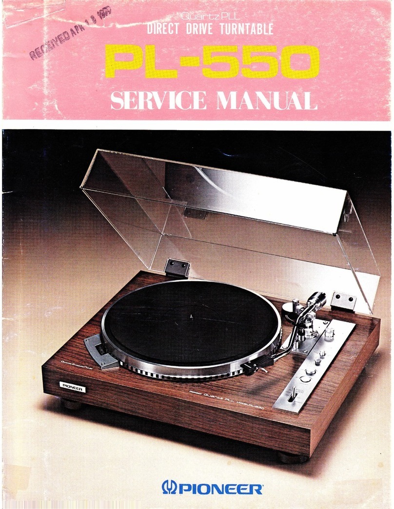
Pioneer
Pioneer PL-200 User manual

Pioneer
Pioneer CDJ-2000NXS User manual