TECHNO-AC Success AG-319G Parts list manual


2
DEVELOPMENT, MANUFACTURING AND SUPPLY OF INSTRUMENTATION
Table of Contents
Introduction. ........................................... 3
1. Appearnce of Receiver .......................... 4
2. OPERATING MODES
............................ 5
3. Receiver menu description .................. 11
3.1. Receiver switching on and menu call .11
3.2. The general view of the menu screen. 11
3.3. Menu parameter selection ...............11
4. Start of work ........................................ 16
5. Search of cables in the mode «Route» . 17
5.1. Cable location in the passive mode ...17
5.2. Search of a communication and
measurement of its burial depth .......18
5.3. GPS ..............................................20
6. Search of communications in the mode
«Graphic» ............................................ 25
6.1. Setting of the receiver for work in the
«Graphic» mode ..............................25
6.2. «Hot» keys for work in the «Graphic»
mode .............................................27
6.3. Search of communications in the mode
«Graphic» .....................................28
7. Search of the utilities in the mode
« Graphic+» .......................................... 29
7.1. Setting of the receiver for work in
the «Graphic+» mode .......................29
7.2. Search of communications in the
mode «Graphic+» ............................29
8. Perfoming the cable location in the
mode «MIN & MAX» ............................. 31
9. Performing cable route location in the
mode «2 frequencies» ......................... 3 2
10. The work mode «Cable selection from
a bunch» .............................................. 34
10.1. The work with the receiver in the mode
«Selection of the cable from a bunch» ..34
10.2. «Hot» keys for the work in the mode
«Selection of the cable from the bunch» 36
11. Mode «Search of defects» using
external sensors ................................ 37
11.1. The work with the receiver in the
mode «Search for defects» .....................37
11.2. «Hot» keys for work in the «Graphic»
mode with DODK and DKI ...............41
12. «Sonde» mode ................................... 42
12.1. Sonde detection and location of the
utility ............................................44
12.2. Declined sonde .............................45
12.3. Measuring the depth of the sonde ...45
Appendix 1 ........................................... 46
Appendix 2. .......................................... 47
Appendix 3. .......................................... 51
Appendix 4. .......................................... 53
13. Transmitter AG-120 .......................... 56
13.1.
Appearance. Controls
.................56
13.2.
Procedure of work with the
transmitter
..........................................57
13.3.
Transmitter connection
................58
13.4.
Turning on the transmitter power
..59
13.5.
Parameter setup
..........................60
13.6.
Modification of the set parameters
62
13.7.
Indication of parameters
..............62
13.8.
Start and stop of generation
........63
13.9. Operation with inductive antenna
6 4
13.10. Operation with the transmitting
clamp
.................................................64
13.11.
Operations under precipitations
. 65
13.12.
External power connection
........65
13.13.
Internal accumulators charging
66
Appendix 5. .......................................... 69
Appendix 6. .......................................... 71

3
DEVELOPMENT, MANUFACTURING AND SUPPLY OF INSTRUMENTATION
Introduction
- Detection of cables and any metal pipelines underground up to 10 m;
- Direct digital measurement of the depth up to 10 m;
- Indication of the deviation from the utility axis in the mode “ROUTE”;
- Direct digital measurement of the current;
- Survey the ground before the excavation works;
- Distance of tracing from the place of transmitter connection is up to 5 km.
Intended use
-Power
-Public utilities
-Oil and gas industry
-Geodesy
-Communication
-Construction
-Other industries
Operation conditions
-Ambient temperature, °С ..........................................from -20С to +60
-Relative humidity, % .................................................up to 85 at t=35 °С
-Pressure, kPa,.............................................................84 to 106
-Device protection class............................................. IP 54
Receiver working principle
«Success AG-319G with integrated GPS/Glonass is used to locate cables and pipelines
underground».
GPS/Glonass and usage logging allow to generate the data and transfer it to the PC via USB
cable and special software program (V1.09 Beta User Manual). 2000 points can be stored.
The Cable and pipe locator «Succces AG-319G» consists of the electromagnetic radiation
receiver and transmitter providing for the electromagnetic radiation of the route being detected.
According to the signal of the embedded speaker or headphones and using the graphic
display indications the operator determines the route location.
The receiver is capable of receiving a signal from industrial frequency radiation sources
(50/60 Hz) and cathode protection systems (100/120 Hz). These modes are used for detecting
the location of cable runs or routes carrying the voltage of the relevant frequency.
Cable or pipeline may be the load for generator. The transmitter can be connected to the
load either directly (with connecting wires) or with the use of the inductive antenna or inductive
clamp providing for contactless (inductive) connection of the utility under examination.
Use of the inductive antenna as a load is only possible at the 8,928 Hz frequency (selected
automatically at antenna connection).
4
DEVELOPMENT, MANUFACTURING AND SUPPLY OF INSTRUMENTATION
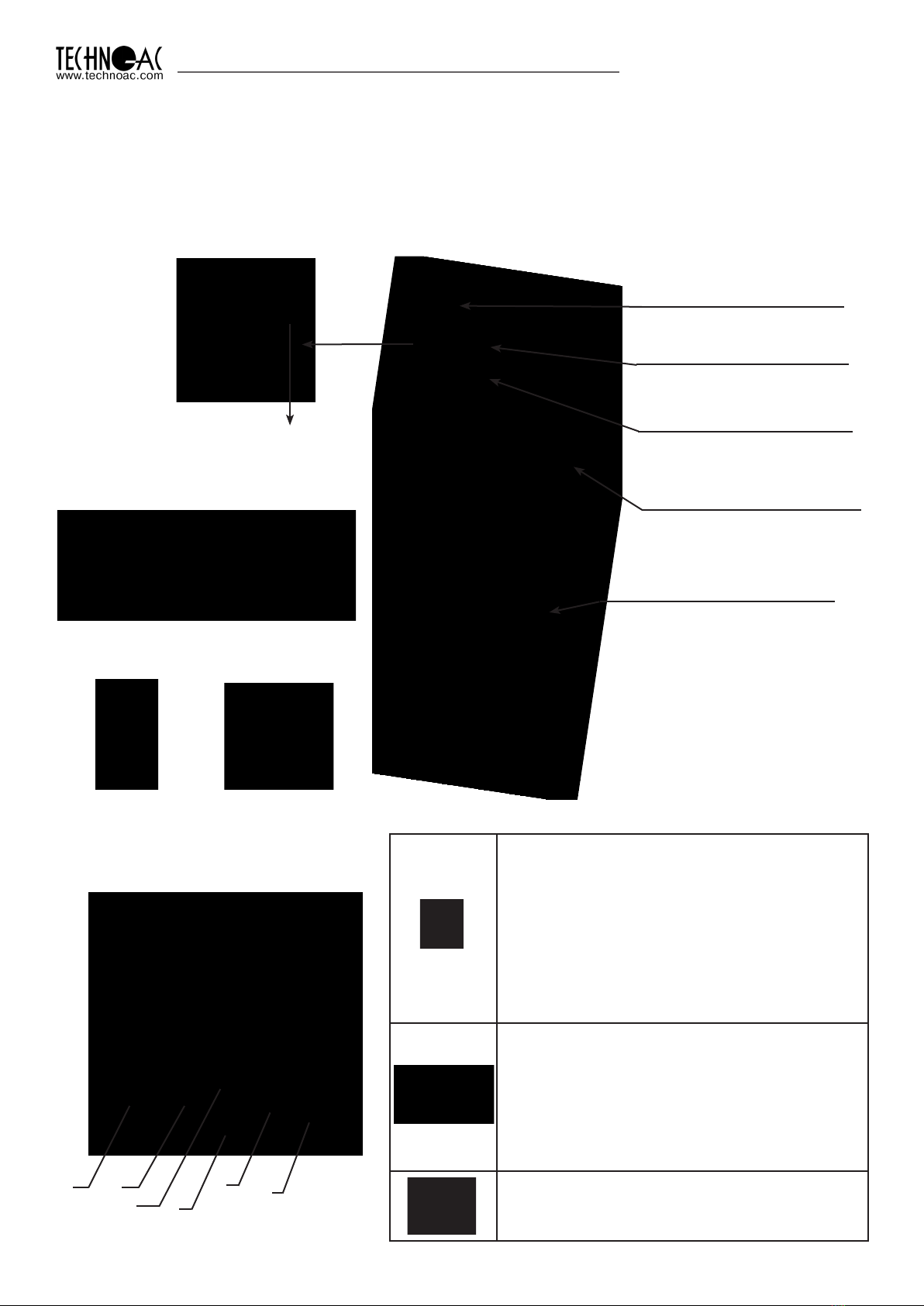
1. Appearance, receiver AP-019.3 controls
The receiver is made in a single block, solid cast IP54 rated body. Up to the battery compartment,
the body provides an IP68 protection rating. Visually, the device can be split into three
components: the face panel with controls and displays, the battery compartment and bottom
which consists of the antenna block. On the rear side of the face panel, there are two slots for
external connections.
External sensor slot
graphical display with
backlight
Сonnection of external sensors.
Sensor DODK-117
Sensor DKI-117
NR-117
Superimposed
frame
CI-105/110
Inductive clamps Face panel, controls
«Power»/«Enter» button (6)
Switching on/off the receiver (to turn off the
receiver, press and hold this button for 2
seconds)
- open menu,
- enter into the editing mode of the selected
menu option,
- exit for the editing mode saving selected
parameters.
Buttons «Up» (3), «Down» (4), «Right» (5),
«Left» (2).
- selection of the menu option (icon),
- selection or changing the parameter inside
the menu,
- fast setting of the parameters
«GPS» button(1)
-Save coordinates and other available
parameters of the point
1 2
34
56
Module of omnidirected
antenna
Battery compartment for
four «type C» batteries
Built-in sound speaker
Six-button
keyboard
Mini-USB port
For PC and
external Power
connection

5
DEVELOPMENT, MANUFACTURING AND SUPPLY OF INSTRUMENTATION
2. OPERATING MODES
2.1 “Route” mode
The ball on the screen shows
the direction in which utility
is located.
When turning on the receiver for the first time, the device will begin in route mode and the service
information will appear. Route mode is the primary screen. Below, the indications are shown, which
are dependent on the operator position near the located utility.
The receiver can’t detect the utility. Position of utility axis shows,
where the utility is situated.
Depth and current measurement
enable automatically, If the utility
indicating line is aligned
with the axis of the receiver.
When above the utility, a solid line
will appear which is perpendicular
to the utility’s direction.
Battery charge level
Type of incoming signal
(continuous or pulse)
Frequency of
the enabled filter
Area where utility axis
visibility
Quick switch to
“graph” mode
Centre of receiver axis
Limits of utility position
where current and depth
measurements are available
Route Mode Description
Amplification coefficient
in dB
* The four-digit number “signal level” (0000 - 4100) represents the intensity of the electromagnetic
field, which is dependent on the filter frequency. The numeric value of the “signal level” becomes
greater when an operator approaches the source of electromagnetic signal of the chosen frequency.
The signal gains its maximum level when the receiver is placed strictly above the utility. The first number
of four-digit figure represents the order of the three-digit figure, generated by other figures: 0 –x1, 1- x10,
2 – x100, 3 – x1000, 4 - x10000. Dynamic range of changing signal levels is 1,000,000 times (120 dB).
Signal level
When approaching the utility,
a blurred line indicates its position.
Utility position indication line

6
DEVELOPMENT, MANUFACTURING AND SUPPLY OF INSTRUMENTATION
When the operator stands strictly
above the utility and the line indicating
the utility is positioned strictly in the
centre field between the two dotted
lines, an automatic depth and current
measurement is performed.
Route Mode and Depth Measurement
In graphic mode, the receiver screen is split into two segments. The upper segment indicates
utility position in 2D, and the lower segment is a moving graph of signal level change in time
according to a “maximum” method, where a maximum signal is reached when the receiver is
positioned strictly above the utility and signal decreases when the receiver is moved further away
from it. In this mode, current and depth measurement function is not available.
2.2 Graphic Mode
Signal level diagram. Every
time image is refreshed, the
graph moves 1 position left
and right position is filled
with new measurement
value
Digit representing current
(far right) value of the graph in
percentage terms. If there is
an incoming signal overload,
a special symbol will be visible
on the screen instead of the
digit “XX”. Indicated data is
incorrect in this case.
Utility position indication
line
2.3 Graphic+ Mode
This mode is different from the ordinary graphic mode. The main difference is that the utility
axis indication line represents only 50/60Hz utilities (power cables or utilities with induced signal)
which can be accidentally met during the operation on active frequencies.
Amplification
coefficient in dB
Graph scale setting
(buttons “up” and “down”
change scale of the graph)
Type of incoming signal
(continuous or pulse)
Frequency
of the enabled filter
Quick switch to route mode.
Press and hold “down” button
for 1 second in order to hide
the graph.
Indication of the frequency
of located energized cable
(can be 50 or 60 Hz)
Signal level moving
diagram
50/60 Hz Utility position
indication line
Frequency filter
(for diagram)
NOTE: When performing a depth
measurement, the receiver antenna
should be positioned perpendicularly
to the utility.
Buried depth
of the utility
Current
of the utility
Receiver and utility
axis are perfectly
aligned

7
DEVELOPMENT, MANUFACTURING AND SUPPLY OF INSTRUMENTATION
2.4 “Minimum maximum”
In “MIN & MAX” mode, the receiver screen is split into two segments. The upper segment is a
moving diagram which represents signal level changes according to the “minimum” method
– it means that the signal will be minimal when the receiver is positioned strictly over the utility. If
the receiver is moved aside, the signal level will increase.
The lower segment represents the “maximum” method diagram – the signal will be maximal
if the receiver is positioned strictly over the utility, and it will decrease if the device is moved further
away.
This mode does not allow depth and current measurements.
Every time image is refreshed,
the graph moves 1 position left
and far right position is filled with
new measurement value
Digit, representing
current (far right) value
of the graph in percentage
terms
Battery charge level
Amplification coefficient in dB
Quick change of diagram scale
Indication of lower
sensor operation (Filter,
Broadband, Radio)
Quick change of lower sensor
operation mode
Type of incoming
signal
(continuous or pulse)
Frequency filter
2.5 Modes with Graphic Representation of “Relative distance to the
Utility” (R.dist.)
In cases given above, both utilities lay beside each other. However, in this case “MIN & MAX” mode
does not allow the user to measure the depth of these cables. For this reason, it is better to use
graphic modes with indication of the “relative distance to the utility”.
While approaching the utility, the value of “relative distance to the utility” changes in the way
described on pictures, shown below:
Parameter value
«R.dist.», indicated
by «∞» symbol
Zones of utility presence
Utilites
Parameter value “R.dist.”
is equal to burial depth
of the utility

8
DEVELOPMENT, MANUFACTURING AND SUPPLY OF INSTRUMENTATION
Utility
This parameter can have values from “0.01” to “30.00”, “>30” and “∞”. Value “∞” are indicated
when the receiver is positioned aside from the utility or when the utility is positioned above the receiver
(an example being when there are overhead voltage lines around). The parameter “relative distance
to the utility” will have its minimum value when the receiver is positioned directly above the utility
axis. In this case, this value is equal to the real burial depth of the utility.
Minimum value of the
parameter - 2.40 is equal to
real burial depth of utility.
The receiver has two modes with indication of “relative distance to the utility”: “R.dis. Graph” is
used when the “relative distance to the utility” graph and utility route are indicated simultaneously,
whilst the “MIN&R.Dist mode“ is used when screen of the receiver indicates 2 graphs (minimal
signal and “relative distance to the utility”).
2.5.1 “R.dis. Graph” mode
This mode is the same as “Graph” mode. The screen is split in two parts, an upper display
and a lower display.
• Upper Part: Route axis indication
• Lower Part: “relative distance to the utility” graph
Indication of “R.dis. Graph”:
Hint: “Hide”– return to
“Route” mode by pressing
button “<” for 1 second
Hint: – change of graph
scale in 2\4 and 8 times by
pressing “up” and “down”
arrows
Graph of changing
“Relative distance to the
utility” in real time

9
DEVELOPMENT, MANUFACTURING AND SUPPLY OF INSTRUMENTATION
When two utilities are buried close to each other while moving the receiver straight across the
utility axis in “R dist” mode, an operator will be able to see the indication shown below:
Minimal values of “relative distance to the utility” indicate the presence of the utility with some
fault because in the case of multiple utilities laying nearby, minimum signal point may move
due to coinfluence of the signals.
You can enable the “R.dis.Graph” mode from “Route” mode by pressing the “>” button or
by switching it in the “Modes” section of the receiver’s main menu.
2.5.2 “MIN & R.Dist” Mode
In this mode the screen is split in two parts. Upper part: Minimal signal graph, lower part: “relative
distance to the utility” graph in real time.
Digit indicates the minimum
signal level of far right point of the
display
Digit indicates relative distance
value of far right part of the
display
“R.dist” value indicated by
“∞” icon
Hint – change of graph
scale in 2, 4 and 8 times
by pressing “up” and
“down” arrows
You can enable “MIN & R.Dist” mode only from “Modes” section of main menu.
2.6 “2 Frequencies” Mode Window
In the “2 frequencies” mode, the cable condition and pipeline protection diagnostic is performed
using the external generator. When conducting works on cable route location, it is possible
to select the communication located as “my own” and perform a route location on it.
Amplification coefficient in dB
The sum of frequency
components (A8+A1)
Frequency components
amplitude modulation
(A8/A1)
Frequency components change
of phase difference
Signal direction
(straight / reverse)
Signal level on 1024
and 8192 Hz
Quick reset of readings
and “reference” to the
utility
Battery charge level

10
DEVELOPMENT, MANUFACTURING AND SUPPLY OF INSTRUMENTATION
IMPORTANT NOTE:
Modes are split in two sets: basic and extended. In basic set, only 3 modes are available:
“Route”,“Graph” and“R.dis.graph”. All modes are available in extended set: “Route”,
“Graph”, “Graph+”, “MIN & MAX”, “2 Frequency”, “Sonde”, “R.dis.graph” and “MIN&R.
dist.”. You can switch between two sets in menu: Settings –> Modes select.
2.7 “Sonde” mode
“Sonde” mode is used for tracing of non-metal pipelines by using a special pipe transmitter
working on 512Hz frequency. (see paragraph 12)
Dynamic Overload Protection
There is protection in the receiver which prevents
the influence of dynamic overload. When the receiver is
operated in the area with tense electromagnetic fields,
this function automatically reduces the incoming signal
and prevents the electronics of the receiver from being
damaged and notifies the user with a special message on
the screen.

11
DEVELOPMENT, MANUFACTURING AND SUPPLY OF INSTRUMENTATION
To open
the
menu,
press
“Enter”.
Menu option
selection is
performed with
buttons
“Up”, “Down”,
“Right” and “Left”.
The menu will appear on the screen. Active “icon” is flashing
and is highlighted by dotted line
To change or
view the menu
item
Values setting is
performed with
the buttons
“Up”, “Down”,
“Right” and “Left”.
The changed value
is immediately
applied.
To exit into the main
menu or switch to the set
mode with the closing
of the menu, press the
“Enter” button. If you
wait for several seconds,
menu will disappear
automatically.
In the upper part of the
indicator, the parameter editing
panel will open.
* If no buttons are pressed for a period of time, the menu will disappear automatically.
The length of this period is set in the “settings” menu option.
3. Menu description
3.1 Receiver switching on
To switch on the
receiver, press
the “Power”
button
Briefly Press
“Enter” button
to open
the menu
3.2 General View of the Menu Screen
Menu option name
Brief menu option
description
3.3 Menu Parameter Selection General Principle
The selected menu
option is highlighted with
the dotted line, flashes
with light/dark
Icons represent each
menu option

12
DEVELOPMENT, MANUFACTURING AND SUPPLY OF INSTRUMENTATION
8 items of menu contain parameters of setting, which are opened in the panel located in the upper part of the
indicator.
№
Item
of the
menu Display image Parameter description
1
Filter The working frequency of the receiver
corresponds to the main frequency
of the applied filter.
It is selected from the set: 50(60) Hz,
100(120) Hz, 512 Hz, 1024 Hz, 8192 Hz
or 32768 Hz.
2
Gain
The amplification coefficient of the scaling
amplifier can be changed from 0 dB to 80 dB
with 2 dB step. The optimum coefficient of
amplification can be selected:
- manually,
- semi-automatically (by command),
- automatically depending on the regime of
the analysis and signal representation.
Table 1
3
Signal
The type of signal received can be
“Continuous” or “Impulse”
Continuous - operation on passive
frequencies 50(60)Hz and 100(120)Hz,
cathodic protection of pipeline.
Impulse or Continuous - on active
frequencies 512, 1024, 8192 and 32768
Hz in accordance with the transmitter.
4
Advanced
Bottom
Sensor
Setting
This option has several settings affecting
the efficiency of the bottom sensor.
• “Filter” (narrow-band filter)
• “WB” (wide band, sensor receives all
frequencies below 8kHz)
• “Radio” (sensor receives all frequencies
over 8kHz)
“Filter” setting is used only in “Route
mode”, other settings are used in
“Graphic” mode

13
DEVELOPMENT, MANUFACTURING AND SUPPLY OF INSTRUMENTATION
5
Base
Mode
Basic set of modes:
- “Route” (2D display of the location of the
utility);
- “Graph” (visually represents the
changes of signal level of surveyed cable as a
diagram along with a 2D representation);
Аdvanced
Mode
Extended set of modes:
- “Graph+” (visually represents the changes
of signal level of surveyed cable as diagram
alongside with 2D representation of 50 (60) Hz
cable;
- “MIN&MAX” (graph representation of
minimum and maximum signals)
- “2 frequency” (amplitude and phase Non-
destructive testing, detection of “friend” or
“foe” signal on two frequencies).
6
Sound Switching on / switching off of sound
notifications created by the built-in speaker.
Has two settings:
-OFF
-ON
7
GPS
GPS Status bar can indicate the following
information:
- GPS module is on.
- GPS setting
- GPS is switched off
- Looking for GPS satellites
- Coordinates of latitude and longitude

14
DEVELOPMENT, MANUFACTURING AND SUPPLY OF INSTRUMENTATION
8
Settings
This menu is opened in the main display
Language <Russian/English>
Text messages language
Modes select <Basic/Extend>
Basic set of modes: “Route” and “Graph”
Extended set of modes: “Route”, “Graph”,
“Graph+”, “MIN&MA” and “2 frequency”
System of units <Metre/Foot>
Measurement system: metrical or imperial
Power
frequency <Europe/USA>
The network frequency for passive search:
Europe (50/100 Hz) / USA (60/120 Hz).
Sound of keys <ON/OFF>
Disables sound for button pressing
Backlight It sets the brightness
of the LED display
It has following values: “0%”, “50%”, “100%”
Delay of menu <1 sec/2 sec/ 3 sec/ 4
sec/5 sec>
Idle time before closing the menu when
no buttons are pressed.
• Popup hints <ON/OFF>
Disables pop-ups with useful hints.
•Self-test <Reset>
Self-test for errors of receiver’s components

15
DEVELOPMENT, MANUFACTURING AND SUPPLY OF INSTRUMENTATION
Settings
LOG
The statistics of device usage including all
applied settings
Reset settings
Reset the device to factory default settings.
After choosing this menu a dialogue window will
appear:

16
DEVELOPMENT, MANUFACTURING AND SUPPLY OF INSTRUMENTATION
With factory settings enabled, you can perform the cable location with network
frequency 50 Hz without the transmitter.
4. Start of work
If alkaline batteries are used - Before start of work, you should install the batteries into the
corresponding compartment of the receiver in the following sequence:
Note
To switch on the receiver, press the “Power” button
Receiver switching
A description of factory settings can be found in the
“settings” menu. You can go back to factory settings by
selecting the “reset settings” option.
Install the batteries,
observing the polarity
Unsnap Battery
compartment. Pull out the
ring on the receiver handle.
Install four new elements into
the battery compartment of the
device, minding polarity.
Install the battery compartment
into the body until it snaps.
The indication of the Firmware version, manufacturer logo and
device name will appear on the screen.
Then, the receiver will automatically enter into “Route” mode
in 5 seconds. When first switching, the factory settings are set by
default . The filter frequency is 50 Hz.
External Power
With the help of the mini-USB cable (included), the operator can connect to external power
sources with 4-7V voltage. For example, a power bank (supplied separately).
The external power source can be placed under overclothes of the operator. It will allow an
extension of the battery life in low temperature conditions. External power can be used with
inserted batteries or without them.
NOTE: Power Bank should be placed as far as possible from the antenna block of the receiver
in order to evade interference.

17
DEVELOPMENT, MANUFACTURING AND SUPPLY OF INSTRUMENTATION
5. Search of Utilities in “Route” mode
Route mode is the main mode for route location of various utilities (cables & pipelines) at all
supported frequencies, both in “passive” cable route location and at the “active” (with the use of
the route locating generator). In passive mode, the cable location is carried out at frequencies
of 50(60) and 100Hz, while cable location in active mode is performed at frequencies of -512, 1024,
8192 and 33Hz.
5.1 Cable Location in Passive Mode
This mode is used to search and locate the route of power cables under voltage with a frequency
of 50(60) Hz and other communications with the induced signal in frequency 50(60) Hz. The
external generator is not used.
Basic Receiver Functions
• Location and tracing of underground utilities with depth measurement in “Route” mode.
• Location and tracing of utilities in “Graph”, “Graph+”, and “MIN & MAX” modes.
• Tracing of non-metal utilities in “Sonde” mode.
• Saving of coordinates and parameters of located points.
• Operation in “2 Frequency” mode (fault location and detection of signal direction).
• Selection of the cable from a bunch with inductive clamp.
Receiver Setting for Operation in “Route” Mode
To enable “Route” mode, please, do the following:
Turn
on the
receiver
Press
“enter”
button
in order
to open
main
menu
Press
“enter”
to enter
the mode
change
menu
Choose
“Modes”
icon
buttons
Choose “Route”
buttons
Press
“enter”
button in
order to
open main
menu
Press “enter”
to enter the
mode change
menu
Then go to
“Filter” menu
buttons
Select 50(60)
Hz frequency
buttons
When filter 50(60)Hz is chosen, the type of incoming signal is automatically set to
continuous.

18
DEVELOPMENT, MANUFACTURING AND SUPPLY OF INSTRUMENTATION
5.2 Search of a Communication and Measurement of its Burial Depth
1. Come to the supposed place of the utility under the voltage or induced voltage in frequency
50(60)Hz.
2. If the utility is far from the operator, you will see on the screen:
3. When moving towards the supposed place of the utility location, the “ball” will appear
on the screen. It shows the presence of a utility and that it is a significant distance from the
operator.
4. The “ball” position shows the direction of the utility relative to the operator.
communication
communication
utility
utility
utility
5. When the operator moves closer to the utility, the axis will move to the centre of the
circle. This means that the operator is standing directly over the utility
utility

19
DEVELOPMENT, MANUFACTURING AND SUPPLY OF INSTRUMENTATION
Power cables most frequently lay at a depth of 60-80 cm, allowing to differ them from
pipelines. It is possible that a cable lays in one channel with a pipeline, when the burial
depth can significantly exceed 1 metre.
If the communication axis cannot be located exactly in the limited area, and the periodical
jumps are happening from one border to the other, it indicates the presence of several
cables under voltage with the 50 Hz frequency. You can specify number and position
of the cables in “Graphic” mode.
Note
In a case when the signal is significantly distorted, the receiver automatically shows
the corresponding notification, offering the option of switching to “Graph” mode.
The receiver switches the
“Graphic” mode
The dialogue box appears “Should
a message about the field
distorted be further displayed?
Attention:
Before measuring the depth of the utility, make sure that your device is positioned perpendicularly to the
utility. Even a slight deviation from vertical position can influence the precision of the depth measurement.
7. Further you should rotate
the device, until the utility axis
is aligned along the receiver
axis. In this position, given
‘f’ (the current in the cable)
is sufficient, the window will
appear displaying its burial
depth and current Now, the
operator stands alongside the
utility.
In this position, it is possible
to move forward and trace
a whole cable).
The measurement of the burial depth of utility
indications of the burial
depth
indications of the
current
Cable

20
DEVELOPMENT, MANUFACTURING AND SUPPLY OF INSTRUMENTATION
5.3 Receiver’s Built-in GPS Operation
Fig.1 Fig.2 Fig.3
The GPS module works simultaneously with GPS and GLONASS signal. The internal memory
and built-in module of the device allow the user to obtain the coordinates and save them together
with several parameters: date, time, burial depth and current (if available) and operating frequency.
The GPS module is enabled from the main menu of the receiver.
When you open GPS menu entry happens the following:
1. The receiver issues module connection command
2 . If a response from the module is received, the receiver requests the number of available
GPS points in module’s memory and shows this information on the screen (see fig 1)
3. If the module doesn’t respond, the receiver shows the message “GPS module not
found” (see fig 2)
After turning on the GPS module, an icon starts to blink in a status bar of the receiver. It
will blink while the receiver is trying to connect to the satellites. When the icon stops blinking, it
means that the connection is established, and the coordinates may be obtained. Also, there
is a small scale near GPS icon which represents GPS signal level. Time of satellite detection
depends on the weather, availability of the satellite and can take up to 10 minutes.
The display of the receiver has the following indication:
1) GPS module status: a) GPS off, b) Looking for GPS satellites
Current GPS coordinates (longitude and latitude in degrees in 5 digit precision)
c) GPS module error
2) GPS ON/OFF button
3) GPS module memory status: shows the number of saved points in relation to available memory
(“13/2300”)
4) YES/NO buttons for module memory clearance: If you select “Yes”, you will see the confirm
dialogue window . Memory clearance is an irreversible action.
“POINT” is a form of entry in the device’s or PC’s memory. It holds current operating frequency
of the receiver, burial depth of the located utility (if available), the current going through the
utility (if available), current longitude and latitude of the receiver position (if available) and also
current date and time (if available).
Saving of the point is performed by pressing the GPS button on the receiver. If the GPS
module is active, it finds the necessary number of satellites and indicates coordinates in the GPS
menu. It means that the following data will be written in the memory: current coordinates, date and
time. If the receiver indicates burial depth and/or current flowing through the utility while saving of
the point is enabled, this data will also be saved in receiver’s memory.
Operating mode of the receiver is saved every time because it is constantly available. When
saving the data to receiver memory, you will see a corresponding message “Saving new
point #X” (where X – is a serial number of the point). The receiver can store up to 2300 points.
Uploading the data to a PC can be performed via USB cable and special software – Mapping
Program.
Table of contents
Other TECHNO-AC Measuring Instrument manuals


