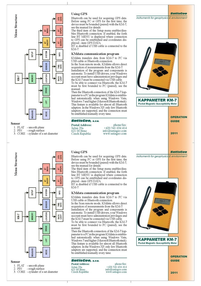
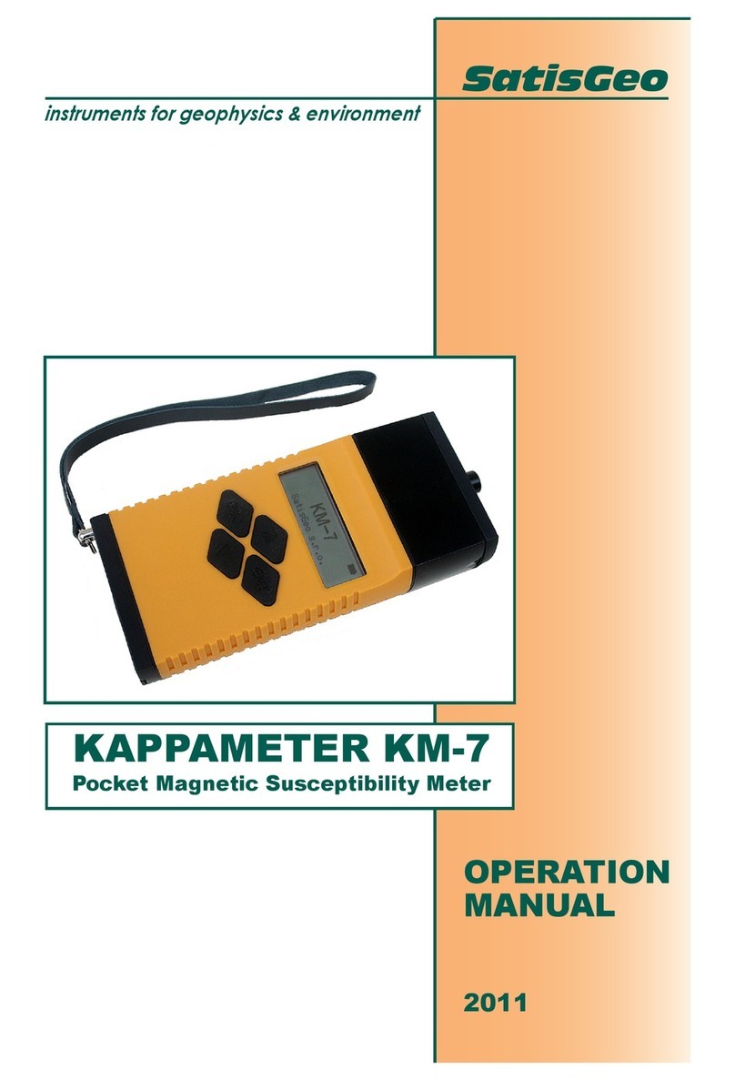
SatisGeo PMG-2 User manual

2021
SatisGeo s.r.o.
1/29/2021
PMG-2 User Manual

1
Contents
1. Introduction...................................................................................................... 3
2. Specifications................................................................................................... 4
3. Description of the instrument............................................................................ 5
3.1. Measuring Sensor With Accessories............................................................. 5
3.2. Processing Unit ............................................................................................ 6
3.3. Operation Principle....................................................................................... 7
3.4. PMG-2 Magnetometer Operating Controls.................................................... 7
3.5. Main Menu.................................................................................................... 7
3.6. Setup Menu.................................................................................................. 8
3.7. Device Menu................................................................................................. 9
4. Putting the instrument into operation...............................................................11
4.1. Power Supply ..............................................................................................11
4.2. Switch On/Off ..............................................................................................11
4.3. Battery Condition Check..............................................................................11
5. Basic setting of the instrument ........................................................................12
5.1. Setting The Internal Clock............................................................................12
5.2. Tuning Of The Magnetometer......................................................................12
5.3. Setting The Backlight...................................................................................14
5.4. Selection Of The Sensor Configuration........................................................14
5.5. Walk Sample Rate Configuration.................................................................14
5.6. Setting The Time Interval To Switch Off.......................................................14
5.7. Setting The Position.....................................................................................14
5.8. Recalling Stored Data..................................................................................15
6. Measurement..................................................................................................16
6.1. Instrument Setup.........................................................................................16
6.2. Sensor Orientation.......................................................................................16
6.3. Tuning .........................................................................................................16
6.4. Manual Measuring.......................................................................................16
6.5. Measuring In Walk Mode.............................................................................17
6.6. Measuring In Auto Mode..............................................................................17
7. Data memory...................................................................................................18
7.1. Erasing And Checking Of The Data Memory ...............................................18
7.2. Data Storage In The Data Memory..............................................................18
7.3. Display Of Data Stored In Memory ..............................................................18
7.4. Transmission of the Stored Data to a Computer..........................................18
8. Supplementary information..............................................................................19

2
8.1. USB Interface..............................................................................................19
8.2. Charger .......................................................................................................19
8.3. Maintenance And Repair Work....................................................................19
8.4. Storage And Transportation.........................................................................19
8.5. Warranty......................................................................................................19
8.6. Accessories.................................................................................................20

3
1.INTRODUCTION
The proton magnetometer and gradiometer PMG2 is a portable instrument which
is powered by an internal battery. It is intended for ground measuring of the absolute
value of the magnetic induction vector of the Earth´s magnetic field by measuring the
frequency of the precession of protons in hydrogen nuclei. The magnetic induction vector
is also called the magnetic field vector.
The magnetometer PMG2 allows the Earth´s magnetic field to be measured in
three modes:
MANUAL mode is used in a profile magnetic survey on a grid. Based on settings
of sensor configuration. In SINGLE sensor configuration, it detects the absolute value of
the magnetic field in the location of the sensor. The sensor is connected to the ‘Up
sensor’ connector. In GRAD sensor configuration, the absolute values of the magnetic
induction vector in the locations of both sensors are measured simultaneously. The
horizontal or vertical gradient of the magnetic field between the two sensors is
determined by subtraction: The value of the field measured in the location of the sensor
connected to the ‘Up sensor’ connector minus the value of the field measured in the
location of the sensor connected to the ‘Down sensor’ connector. The gradient
measurement removes, to some extent, the undesirable influence of disturbing fields,
compensates for the influence of the regional field, and does not depend on diurnal
variations in the Earth´s magnetic field.
WALK mode continually measures the magnetic field based on sensor
configuration in three intervals 0.5s, 1s, 1.5s, 2s, 2.5s, and 3s. The possible sensor
configuration is the same as in manual mode. The measurements in this mode can be
burdened with a more significant error than in MANUAL or AUTO measurements.
AUTO mode allows repeated measurements with one sensor in set time intervals.
Both the starting time and the length of the intervals can be set before the
measurements. This mode is used for measuring diurnal variations in the Earth´s
magnetic field.
The results of the measurements can be stored in internal memory. The data can
be transmitted to a computer through a USB interface using the communication program,
which is supplied with the instrument. The program saves the data in a gzipped XML file
of the external computer.
The magnetometer PMG2 is delivered with a power supply, which is a built-in
lead-acid battery. The non-magnetic rechargeable battery does not contribute enough to
the magnetic moment of the instrument to affect measured values. A battery charger is
also supplied with the device.
All functions of the magnetometer PMG2 are controlled by an internal
microprocessor. This internal microprocessor allows an operator to communicate with the
instrument via a keyboard and LCD display, controls the measurement process, and
transmits the acquired data to an external computer through the USB interface.
The proton magnetometer automatically checks the correctness of the
measurement and of the activities of the operator. If a failure is detected, the operator is
warned with an error message on display.

4
2.SPECIFICATIONS
Measuring range
20 000 to 100 000 nT
Resolution
0.01 nT
Absolute accuracy
±0.5 nT
Sensitivity (AUTO, MANUAL, WALK
@ > 1.5s)
0.2nT
Maximum gradient value *
1 000 nT/m
Maximum displayed value of gradient
9999.9 nT
Measuring cycle
ca 0.5 s
Triggering
Manual, automatic in AUTO and WALK mode
Internal clock
day, month, year, hours, minutes and seconds,
independent of battery condition
Data memory
1,800,000+ readings
Universal Serial Bus (USB)
Power supply
internal lead-acid battery 12 V / 3.4 Ah
Battery lifetime
5 000 readings on average in GRAD sensor
configuration
Processing unit
Dimensions
230 x 80 x 170 mm
Weight
3.2 kg including battery
Sensor
Dimensions
dia 80 x 200 mm
Weight
0.7 kg
Operating temperature range
- 10 to 60 °C
Storage temperature range
- 20 to 70 °C
* The maximum gradient 1000nT/m means that if a change in gradient in consecutive
measurements is smaller than 1000nT, there is no need to change the tune significantly,
and we are sure that results are reliable.
Otherwise, there are two scenarios.
1. In the case that there was no need to change the tune for either of the probes
significantly, the results are as well reliable.
2. In the case that there was a need to change the tune for either of the probes
significantly, the results are not reliable. The user is informed that such a situation
occurred and that the tune changed. So to get reliable results, an additional
measurement in the same place needs to be taken.

5
3.DESCRIPTION OF THE INSTRUMENT
The proton magnetometer PMG2 consists of a processing unit, measuring
sensors, and a post.
3.1. Measuring Sensor With Accessories
The measuring sensor contains two coils properly arranged to suppress a
disturbing external field. The coils are placed in a laminated cylinder container filled with
a liquid rich in hydrocarbons.
North and south are marked on the container of the sensor. The ‘north’ mark
should point to the geographical north. The orientation of the sensor does not affect the
value of the measured magnetic field, but it does affect the intensity of the signal from the
sensor and, thus, the size of the error of the measurement.
Figure 3.1 - Post assembly for line measurement.
For measurements, the sensor is mounted on a post which is assembled using up
to five half meter long sticks joined with screw coupling. In this way, the sensor can be
set to various heights above the ground –see Figure 3.1. For gradient measurement, an
extension (gradient stick) is used to keep both sensors 0.5 or 1 m apart –see Figure 3.2.
The gradient stick allows the position of the sensors to be set so that the orientation of
both sensors to the Earth´s magnetic field may be the same. For AUTO mode
measurements (diurnal variations), an anchor ring with ropes and pins is supplied to hold
the post in place.
The measuring sensors and the processing unit are connected via 2.5 m long
cables.

6
Figure 3.2 –Left –post assembly for gradient measurement.
Right –post assembly for magnetic variation measurement.
3.2. Processing Unit
The processing unit allows for communication with an operator via a keyboard
and a graphic LCD display. It contains circuits for processing and analyzing the
measured signal: tuning circuits, low-noise amplifier, filter, and shaping amplifier.
The processing unit is placed in a duralumin box. Two watertight bayonet
connectors for connecting the sensors are located on the left side of the box. In AUTO
mode, only the upper left connector is used, ‘Up sensor’. In MANUAL and WALK modes,
the booth connectors can be used based on sensor configuration. The gradient is
determined by subtraction: The value of the field measured in the location of the sensor
connected to the ‘Up sensor’ connector minus the value of the field measured in the
location of the sensor connected to the ‘Down sensor’ connector.
There are two connectors on the right side of the box. The upper one serves to
connect to the computer through USB. The connector for charging of the internal battery
is located in the lower part of the instrument. The connector can also be used for an
external power supply after removing the internal battery.
The lead-acid battery is placed in the bottom part of the unit and is accessible by
unscrewing the four bolts in the bottom cover. The battery compartment is hermetically
separated from the electronics.
The display and the keyboard are located on the top side of the unit. The
keyboard contains 16 watertight membrane push-buttons.
The instrument is delivered with a harness to fasten it on the chest of an operator.

7
3.3. Operation Principle
The measurement of the magnetic field is conducted in two steps. In the first
measuring step, the polarization current feeds the sensor and causes uniform orientation
of magnetic moments of hydrogen nuclei contained in the liquid in the sensor. The time of
polarization is automatically increased, in MANUAL and AUTO measuring modes,
according to the decreasing source voltage so that the precession signal gained from the
sensor may remain constant. In WALK measuring mode, the polarization time is fixed.
During the polarization cycle, the sensor and the low-noise amplifier are disconnected.
The first step of the measuring sequence is terminated by switching the polarization
current off.
In the second step, due to an interruption of the polarization current in the sensor,
the transient field is dumped, and then the low-noise amplifier is connected to the sensor.
The signal induced in the sensor is amplified, filtered, and shaped to suit the processing
in numeric circuits. In the sampling circuit of the microprocessor, the frequency of
attenuated oscillations of the precession motion of the hydrogen nuclei is evaluated. The
frequency is directly proportional to the measured magnetic field.
The entire measuring cycle is controlled by a microprocessor which computes the
measured magnetic field and statistical error of the measurement from the value of the
frequency of the precession. Both values are displayed and optionally stored in the data
memory.
During the second step, the amplitude of the precession signal and the time
constant of the decay are determined. The supplementary values are also stored in the
data memory.
3.4. PMG-2 Magnetometer Operating Controls
[ON / OFF]
switching on and off
[ENTER]
start of measurement or other selected procedures, setting validity of
modified parameters or data, storing measured data in the memory
[ESC]
termination of any going-on procedure without storing data
[NEXT]
next item
[0] to [9]
loading digits
[ v ]
scanning series of consecutive data towards higher ordinal numbers
[ ^ ]
scanning series of consecutive data towards lower ordinal numbers
Table 3.1 - PMG-2 operating controls.
3.5. Main Menu
After switching the instrument on, by means of the push-button [ON/OFF], the
initial logo appears on display.
After pressing any push-button or after 3 seconds, the main menu appears.
The backlight is switched off automatically 30 seconds (default value is 30 s, other
options selectable) after the last pressing of a push-button. The backlight can be
switched off all the time to save power consumption.

8
S 08:04:28
MAIN MENU
1. MEASURE
2. POSITION
3. MEMORY
4. SETUP
Line:+1026 Pos:-0980
The topmost part of the display is reserved for actual time and status information.
The status indicators are:
this icon indicates that the USB cable is connected, and the device is ready for
data transfer.
this is a battery icon to indicate battery status.
S or G symbols indicating the actually select sensor modes Single, Gradient.
Move-in the main menu, and item selection is marked by a cursor, graphically
indicated by the inverted line. Push-buttons [] and [] serve for a cursor move in the
main menu. Menu items 1 - 4 are directly selectable by pressing numerical push-buttons
[1] - [4] on the keyboard.
Push-button [ENTER] serves for item function activation and to confirm the newly
specified parameters. Push-button [ESC] serves to return to the main menu without
modification of parameters.
1. MEASURE –item sub-menu serves to activates measurement. The possible
measurements are MANUAL, WALK, and AUTO. See chapter 6.
2. POSITION - Item serves for the setting of a number of a profile line, position on a
profile, and step of measurement on a profile see chapter 5.7.
3. MEMORY - Item serves for a listing of the items stored in the data memory.
Further, it enables us to erase the data memory and see memory status see
chapter 7.
4. SETUP - Item serves to set up various parameters of the instrument see chapter
3.6.
3.6. Setup Menu
The setup menu serves to set up various parameters, see below. It is activated in
the main menu, item 4.
Move-in the setup menu, and item selection is marked by a cursor, graphically
indicated by the inverted line. Push-buttons [] and [] serve for a cursor move in the
main menu.
Menu items 1 - 5 are directly selectable by pressing numerical push-buttons [1] -
[5] on the keyboard.
Push-button [ESC] serves to return to the main menu.
Push-button [ENTER] serves for item function activation and to confirm the newly
specified parameters.

9
Push-button [ESC] serves to return to the setup menu without modification of
parameters.
S 08:04:28
SETUP MENU
1. MODE
2. TUNE
3. WALK MODE
4. DEVICE
1. MODE –item sets the sensor mode (Single or Gradient) for MANUAL and
WAL measure. This item is shown in the case that the device is a gradiometer.
2. TUNE –item servers to select the current field range see chapter 5.2.
3. WALK MODE –item serves to select automatic measure interval for WALK
measure.
4. DEVICE –item serves to select multiple device options. See chapter 5.
3.7. Device Menu
The device menu serves for setting up various device parameters, see below. It is
activated in the setup menu, item 5.
S 08:04:28
DEVICE SETUP
1. BACKLIGHT
2. DATE / TIME
3. OFF TIME
4. INFO
1. BACKLIGHT - Item serves to switch the backlight on / off or to set the time to
elapse. See chapter 5.3.
2. DATE / TIME - item sets up real date (yy.mm.dd, where y- year, m –month, d
–day) and time (hh:mm:ss, where h - hours, m - minutes, s - seconds). The
cursor indicates the number to edit. Editing of numerical values is carried out
by means of push-buttons [0],[1],[2],...[9]. Move the cursor by [], [], and
[NEXT]. The push-button [ENTER] stores the modified date and time into the
memory. The push-button [ESC] returns the control to the parent menu
without any change of the date and time see chapter 5.1.
3. OFF TIME - item serves for setting the switch-off time see chapter 5.6.
4. INFO - Item displays the serial number of the instrument and version of the
software.

10

11
4. PUTTING THE INSTRUMENT INTO
OPERATION
4.1. Power Supply
The instrument is delivered with a built-in hermetically closed lead-acid battery
12V / 3.4Ah. The battery compartment is accessible from the bottom part of the box by
unscrewing the four bolts fastening the bottom cover of the instrument.
The internal battery can be charged directly in the instrument with the charger
supplied with the device.
4.2. Switch On/Off
The first check of the instrument function can be performed with the processing
unit without connecting the sensor. The instrument is switched on by pressing [ON /
OFF]. A startup logo appears on display.
In the case of a faulty power supply, an error message is displayed. If the battery
is deeply discharged, the instrument automatically switches off.
Also, the instrument automatically switches off if the time interval AutoPowerOff
elapses, and there are no activities of the operator on the keyboard or through the USB
interface. The interval can be set in the Setup menu, item Time.
If the instrument does not display the above-mentioned information even after
repeatedly pressing [ON /OFF], it means there is an instrument failure. It is
recommended to contact the distributor or the manufacturer.
4.3. Battery Condition Check
The battery condition check is performed automatically each second after the
instrument is switched on. The voltage levels for error messages about the battery
discharge were set from the discharge characteristics according to the power
consumption at the time of the check. If an error message about the battery discharge is
displayed, it is necessary to charge the battery or to replace it with a charged one. The
software does not allow the operation of the instrument if the battery is deeply discharged
and switches it off automatically. Thus, erroneous operation and damage of the battery
are prevented.
If the instrument is not used for a long time, the battery should be checked and
charged at least twice a year.

12
5.BASIC SETTING OF THE INSTRUMENT
5.1. Setting The Internal Clock
Time and date can be modified in the device setup menu, item DATE / TIME. A
cursor indicates the place to be modified by numeric push-buttons. The cursor is moved
by pressing [ v ] and [ ^ ]. The push-button [NEXT] moves the cursor to the date that can
be modified similarly.
The modified time and date are updated after pressing the [ENTER]. The
procedure can be terminated without changing the actual time by pressing [ESC], and the
control returns to the setup menu.
S 08:04:28
SET TIME
DATE: YY.MM.DD
2020.01.01
TIME: HH.MM.SS
08:15:50
5.2. Tuning Of The Magnetometer
Considering the character of the signal processed by the analog part of the
instrument, it is necessary to tune input circuits at least approximately to the measured
magnetic field. To display the current tuning interval, select the TUNE sub-menu,
MANUAL SET item in the setup menu. For the SINGLE mode the display shows for
example:
S 08:04:28
SET TUNE
Sensor: UP
41600 –43800nT
43500 –45800nT
45500 –48000nT
Auto tune: ON
The word On/Off indicates if the function of the automatic tuning of input circuits is
on or off. The automatic tuning can be switched on or off by pressing [ v ] and [ ^ ].
[NEXT] moves to the next item. The interval of the magnetic field can be selected by
pressing [ v ] and [ ^ ] according to the awaited value.
The tuning configuration can be performed automatically as well. The automatic
tuning is started by selecting AUTO SEARCH in the TUNE menu. The automatic tune
goes through all possible tune ranges and select tune range with sufficiently high signal
amplitude and minimal statistical error. After the end of the automatic tuning, the result is
displayed on display, and the user can confirm if to use found range as an actual tuning
setting.

13
The tuning intervals are:
1. 20 000 - 21 000 nT
19. 45 500 - 48 000 nT
2. 20 900 - 22 000 nT
20. 47 700 - 50 200 nT
3. 21 900 - 23 000 nT
21. 49 900 - 52 600 nT
4. 22 900 - 24 100 nT
22. 52 300 - 55 100 nT
5. 24 000 - 25 200 nT
23. 54 800 - 57 700 nT
6. 25 100 - 26 400 nT
24. 57 400 - 60 400 nT
7. 26 300 - 27 700 nT
25. 60 100 - 63 200 nT
8. 27 500 - 29 000 nT
26. 62 900 - 66 200 nT
9. 28 800 - 30 400 nT
27. 65 900 - 69 300 nT
10. 30 200 - 31 800 nT
28. 69 000 - 72 600 nT
11. 31 600 - 33 300 nT
29. 72 300 - 76 000 nT
12. 33 100 - 34 800 nT
30. 75 700 - 79 600 nT
13. 34 600 - 36 400 nT
31. 79 300 - 83 300 nT
14. 36 200 - 38 200 nT
32. 82 900 - 87 300 nT
15. 38 000 - 40 000 nT
33. 86 800 - 91 400 nT
16. 39 700 - 41 800 nT
34. 90 900 - 95 700 nT
17. 41 600 - 43 800 nT
35. 95 300 - 99 999 nT
18. 43 500 - 45 800 nT
Table 5.1 - Tuning intervals.
A preliminary approximate setting of the tuning point can be performed on the
basis of a magnetic field map - see Figure 5.1 in dependence on the geographic
coordinates of the location of measurement or automatic search can be used. An error
message indicates if the measured value of the magnetic field is not within the tuning
interval. If the automatic tuning is on, the input circuits will be automatically tuned at the
next measurement.
The modified tuning interval is stored in the memory after pressing [ENTER]. By
pressing [ESC], the tuning procedure is terminated without changing the interval.
For the GRAD sensor mode, the tuning should be repeated twice for each sensor
(both UP and DOWN) separately. The automatic tuning (On/Off) is the same for both
sensors.
Figure 5.1 –Earth’s magnetic field.

14
5.3. Setting The Backlight
The backlight is switched on or off by selecting the radio button in the setup menu,
item backlight. It can be modified by [ v ] and [ ^ ]. Power consumption is relatively high
when using backlight, so it is recommended to set the time to the minimum value.
5.4. Selection Of The Sensor Configuration
The item MODE is accessible only if the device is the gradiometer. The item
MODE in the setup menu allows the selection of one of the two sensor modes: SINGLE
and or GRAD. The currently selected mode is marked with the radio button. It can be
changed by [ v ] and [ ^ ].
The pressing of the push-button [ENTER] asserts the selection, [ESC] terminates
the procedure without changing the mode.
5.5. Walk Sample Rate Configuration
The item WALK MODE in the setup menu allows the selection of one of the three
sample rates for the WALK measure mode. The currently selected mode is marked with
the radio button. It can be changed by [ v ] and [ ^ ].
The pressing of the push-button [ENTER] asserts the selection, [ESC] terminates
the procedure without changing the mode.
5.6. Setting The Time Interval To Switch Off
To protect the lead-acid battery, the instrument is automatically switched off after
elapsing the set time interval after the last activities of the operator on the keyboard.
Thus, the deep discharge and the damage of the battery are prevented even if the
operator forgets to switch off the instrument. The default value is 20 min.
In the setup menu, item TIME, the AutoPowerOff time is displayed. After elapsing
of the time, the instrument is automatically switched off. The format is hh:mm, where hh
stands for hours, mm for minutes.
[ENTER] asserts the new value, [ESC] terminates the function without saving the
changes.
S 08:04:28
SET AUTO POWER OFF
OFF TIME: HH.MM
00:20
5.7. Setting The Position
The item POSITION in the main menu sets the position of the next measurement
that will be conducted. The information is stored in the data memory together with the
measured value. The position consists of the profile number ‘Line’, the position on the
profile ‘Pos.’ and the spacing ‘Step’, which is the increment or decrement of the next
position ‘Pos.’. If the ‘Step’ is positive, the value of the next ‘Pos.’ stored with the
measurement in the data memory is increased by the value of the ‘Step’, if the ‘Step’ is
negative, the value of the next ‘Pos’ is decreased. This allows the operator to move to the
end of the profile, to higher positions, and also back to the lower positions.

15
By selecting the item POSITION in the main menu, ‘Line’, ‘Pos.’, and ‘Step’ can
be edited. The current values are displayed, for example:
S 08:04:28
SET POSITION
Line: +01026
Pos.: -00980
Step: +10
A cursor appears at the place of the digit to be modified and can be moved by [ v ]
and [ ^ ]. The value ‘Line’ can be set from -99999 to 99999. By pressing [NEXT] the
second item, the current position on the profile ‘Pos.’ can be modified.
The value of ‘Pos.’ can also be set from -99999 to 99999 the same way as with
the profile. Another pressing of [NEXT] allows ‘Step’ to be edited.
The value of the ‘Step’ can be set from -99 to 99 the same way as above. By [ v ]
and [ ^ ], the digit to be modified is selected, and by numeric push-buttons [0] to [9], it is
changed.
The sign + and –is changed by pressing [0] when the cursor is placed at the sign.
[NEXT] is used for switching among the items ‘Line’, ‘Pos’, and ‘Step’. The
modified data are stored in the memory by pressing [ENTER]. Pressing [ESC] terminates
the function without saving the changes.
5.8. Recalling Stored Data
The item LIST in the memory menu is used to display the data stored in the data
memory. The sored data are browsed by measurement type manual, walk, and single.
After entering it, the last measurement is displayed. By pressing [ v ] or [ ^ ], the
following or the previous measurement is displayed.
S 08:04:28
Line:+1026 Pos:-0980
Single:
45123.4 ±02.3nT
Amp:5 D:0.5s
08.06.2012 15:38:44
In the SINGLE sensor configuration profile number and position number, the value
of the magnetic field, error of the measurement, signal intensity, time constant of the
decay of the signal are displayed. In the GRAD sensor configuration, appropriate values
are displayed.

16
6.MEASUREMENT
The instrument and its accessories are transported in a case. It must be
assembled before an operation.
The measured value of the magnetic field depends very much on the presence of
metal objects near the sensor. The operator should remove all the metal objects prior to
measuring.
6.1. Instrument Setup
Screw together the sensor and the sticks of the post to the desired length –see
Figure 3.1. The processing unit can be attached to the harness and carried on the chest.
Connect the sensor to the processing unit by using the appropriate connectors. In
the single sensor configuration and AUTO modes, the connector ‘Up sensor’ is used. In
the GRAD sensor mode, both sensors are used. The upper sensor should be connected
to the ‘Up sensor’ connector otherwise the sign of the gradient value is changed.
It is recommended to keep the sensor as far as possible from the processing unit
to limit the influence of the magnetic moment of the instrument.
For the same reason, it is recommended to keep the direction of the advance
along with the profile during the measurement in one area.
6.2. Sensor Orientation
The measured value of the magnetic field does not depend on the sensor
orientation. However, with the changing orientation of the sensor towards the Earth’s
magnetic field, the signal from the sensor is changed, and the statistical error of the
measurement increases. To achieve the maximum signal the sensor must be oriented in
the north-south direction, so the ‘north’ mark on the sensor must point to the geographical
north.
6.3. Tuning
Before measuring in a new area, it is necessary to set or check the preliminary
tuning of the instrument according to the map of the Earth’s magnetic field, see Figure
5.1. If the measurement is conducted with inaccurately tuned circuits, an error message
is displayed. If the automatic tuning function is on, the tuning will occur automatically
concerning the measured value. The automatic tuning is not performed in the case of an
enormous difference in which the value of the magnetic field is measured with a
significant statistical error. The tuning procedure is described in chapter 5.2.
6.4. Manual Measuring
MANUAL measuring is started by selectin MANUL in the measure menu. The
selection is asserted by [ENTER]. The instrument is prepared to measure in the single
and or gradient sensor configuration. The sensor configuration can be selected in the
setup menu item MODE see chapter 5.4. In the single sensor configuration, the
instrument measures the absolute value of the magnetic field vector. In the gradient
sensor configuration, the device measures the value of the magnetic field in both
locations of the sensors simultaneously. The displayed value of the gradient is
determined by subtracting the value of the magnetic field of the sensor connected to the

17
‘Down sensor’ connector from the value of the magnetic field of the sensor connected to
the ‘Up sensor’ connector.
If the position on a grid should be used, the position of the first measurement
must be set, which means setting the items ‘Line’, ‘Pos’, and ‘Step’ in the POSITION item
of the main menu. This is described in detail in chapter 5.7. The measurement is started
by pressing [ENTER]. After about 2 seconds, the measured value of the magnetic field
with the statistical error is displayed, as well as the position of the measurement point
‘Line’ and ‘Pos’ and other information.
S 08:04:28
46347.2 ±05.6nT
Line:+1026 Pos:-0980
Amp:8 D:0.6s
Save? ENTER/ESC
The value Amp means the signal intensity, and the value D expresses a time
constant of the decay of the precession signal. The question at the bottom indicates the
option to store the reading in the data memory.
By pressing [ENTER], the reading is stored in the data memory, and the next
position is displayed. By pressing [ESC], the measured data is erased, and the current
position is displayed.
6.5. Measuring In Walk Mode
The WALK measure mode is selected in the MEASURE menu. In this mode, the
instrument is prepared to measure int the single and or gradient of the Earth’s magnetic
field based on sensor configuration. The sensor configuration can be selected in the
setup menu item MODE see chapter 5.4.
In the WALK measure mode, the measurements are continually repeated and
saved to memory. The repetition interval is selectable int setup menu item WALK MODE.
The intervals are 0.5s, 1s, and 1.5s see chapter
6.6. Measuring In Auto Mode
The AUTO measure mode is selected in the MEASURE menu. In this mode, the
instrument is prepared to serve as a base station and measure diurnal variations. When
the measurement is started, two items are displayed: ‘Start time’ sets the time of the first
measurement of the base station.
‘Interval’ sets the time interval between measurements.
The results of the measurement in the AUTO mode are stored automatically in the
data memory.
The measurement in the AUTO mode is terminated by switching the instrument
off.

18
7.DATA MEMORY
The instrument is equipped with a large memory where all readings and identifiers
can be recorded. The capacity of the data memory is more than 1 800 000 readings. The
readings obtained in various modes can be stored sequentially. The stored data can be
displayed or transmitted to an external computer through the USB interface.
It is useful before the beginning of the measuring in a new area to transmit data
stored in the data memory to the external computer and to erase the data memory. Thus,
the data memory is set to maximum capacity.
7.1. Erasing And Checking Of The Data Memory
The stored data will be erased during the erase procedure. Therefore it is
necessary to transmit the data to an external computer before the procedure.
The erasing procedure starts by selecting the item ERASE in the memory menu.
To prevent occasional erasing of the memory, the operator is repeatedly asked to confirm
the operation. Only after pressing [NEXT] the data memory will be deleted.
7.2. Data Storage In The Data Memory
In the MANUL measurement mode after a measurement, the result is displayed
as well as the profile number and the position on the profile of the measurement point
and other information. To store the data, the operator presses [ENTER], otherwise [ESC]
(canceling the measured value), and the measurement on the point can be repeated. The
position of the next measurement is displayed in both cases. The position can be
changed in the item POSITION.
In the AUTO and WALK measurement modes, the measured data are stored
automatically, and the profile number and the position on the profile are not incremented.
7.3. Display Of Data Stored In Memory
The data stored in the data memory can be displayed or transmitted through the
USB interface to a computer.
The data is displayed in the item LIST of the memory menu and selection of the
measurement type (MANUL, WALK, AUTO). After entering the item, the last stored data
is displayed. Pressing [ v ] or [ ^ ] displays the following or the previous reading.
Continually pressing [ v ] or [ ^ ] increases the speed of the scanning. A notice is
displayed if the data memory is empty and when there is a beginning of the data memory.
7.4. Transmission of the Stored Data to a Computer
Before the transmission of the stored data to an external computer, it is necessary
to connect the instrument and the computer with the USB cable.
On the computer, it is necessary to run the program, which allows the data to be
transmitted from the magnetometer to the computer and stored in a gzipped XML file
format.
The measured data can be as well exported to a text file for further processing.

19
8.SUPPLEMENTARY INFORMATION
8.1. USB Interface
The magnetometer PMG2 can be directly connected with a computer through the
USB cable supplied by the manufacturer.
The program supplied with the instrument transmits data from the magnetometer
to the external computer.
8.2. Charger
The charger is delivered with the instrument, allowing careful and optimum
charging of the built-in lead-acid battery 12 V / 3.4 Ah, to use its full capacity and lifetime.
The product is double insulated.
The charger automatically sets the optimum charging mode according to the
condition of the battery. There is no danger to damage the battery from overcharging.
Operation:
1. Plug the connector of the charger cable in the connector on the lower right part of the
instrument.
2. Switch on the charger by plugging it in.
3. The battery is charged when the pilot light turns off.
8.3. Maintenance And Repair Work
Under normal operating conditions, the magnetometer requires no special
maintenance. Only the built-in lead-acid battery needs care. If the voltage drops under a
certain level, the battery might be damaged, or the magnetometer might not operate
correctly, so the instrument is switched off automatically. When the device is not used for
a long time, it is still discharging and must be charged at least once a half-year.
Because of the complexity of the instrument, it is strongly recommended not to
make any interference with the electronics.
In the case of a failure of the magnetometer, the customer should contact the
distributor or the manufacturer. The service will be performed as soon as possible.
8.4. Storage And Transportation
The packed instrument can be stored and transported in the range of
temperatures -20° to 70°C and at the relative humidity of up to 90%.
The built-in lead-acid battery should be checked and charged with the supplied
charger at least once a half-year.
8.5. Warranty
The manufacturer provides a two-year warranty after the purchase of the proton
magnetometer PMG2. Other information relating to the warranty is given in the warranty
certificate.
Table of contents
Other SatisGeo Measuring Instrument manuals