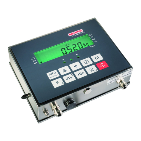
Techno Trade TBOX MS User manual

A
R
emote
T
erminal
U
nit
User’s Guide
Technical specifications & cabling

Version: 1.06 2
Disclaimer
Every effort has been made to ensure the accuracy of the information in this guide. However, Techno Trade S.A.
assumes no responsibility for the accuracy of the information. Product information is subject to change without
notice.
TWinSoft
and
A
are registered trademark of Techno Trade s.a.
Windows '95, '98, NT, 2000, XP are trademark of Microsoft Corp.
Internet Explorer is a trademark of Microsoft Corp.
Copyright
©2004-2006 by Techno Trade SA
Edition: February 7, 2006

Version: 1.06 3
TABLE OF CONTENTS
PRESENTATION ................................................................................................................7
1. H
OW TO USE THIS MANUAL
?..............................................................................10
1.1.
What is in the manual?......................................................................................... 10
1.2.
What is not in the manual?................................................................................... 10
2. T
HE
H
ARDWARE
C
ONCEPT
................................................................................11
2.1.
The Racks............................................................................................................ 11
2.2.
The Cards............................................................................................................ 12
HARDWARE.....................................................................................................................13
3. I
NSTALLATION OF THE
R
ACK
..............................................................................14
3.1.
Installation of the Rack on a DIN rail..................................................................... 14
3.2.
Installation of the Rack in a 19’’ cabinet................................................................. 15
4. I
NSERTION OF
C
ARDS IN THE
R
ACK
....................................................................16
4.1.
The Power supply................................................................................................. 16
4.2.
Placing the Power Supply Card.............................................................................. 17
4.3.
Working without Power Supply Card...................................................................... 18
4.4.
Hardware vs. Software Address of Cards ............................................................... 19
4.5.
Powering ............................................................................................................. 22
TWINSOFT - GETTING STARTED ....................................................................................25
5. I
NSTALLATION OF
TW
IN
S
OFT
............................................................................26
5.1.
System requirements............................................................................................ 26
5.2.
Installation of the CD-ROM ................................................................................... 27
5.3.
Programs of ‘TWinSoft Suite’................................................................................. 29
6. S
TARTING
TW
IN
S
OFT
......................................................................................30
6.1.
Wizard................................................................................................................. 31
6.2.
Communicating with TBox MS............................................................................... 32
6.3.
PC Communication Set up..................................................................................... 32
6.4.
Testing communication......................................................................................... 34
6.5.
Global reset of TBox MS........................................................................................ 35
6.6.
LED « RUN »........................................................................................................ 35
6.7.
Saving and Sending a Program.............................................................................. 36
6.7.1.
Saving a document ..................................................................................................36
6.7.2.
Compiling a document..............................................................................................36
6.7.3.
Sending a document ................................................................................................37

Version: 1.06 4
TWINSOFT - PROGRAMMING.........................................................................................39
7. I
NTRODUCTION
..............................................................................................40
8. RTU
PROPERTIES
...........................................................................................41
8.1.
General properties................................................................................................42
8.2.
Drivers.................................................................................................................43
8.3.
Security ...............................................................................................................43
8.4.
Info properties .....................................................................................................44
8.5.
Advanced.............................................................................................................44
8.5.1.
Startup...................................................................................................................44
8.5.2.
Alarms....................................................................................................................45
8.5.3.
Sampling Tables......................................................................................................47
8.5.4.
Temperature...........................................................................................................48
8.5.5.
Remote Tags...........................................................................................................48
8.5.6.
TCP/IP....................................................................................................................48
8.5.7.
Environment variables..............................................................................................50
9. R
ESOURCES
...................................................................................................51
9.1.
The CPU-16 card ..................................................................................................51
9.1.1.
Communication ports of the CPU ..............................................................................52
9.2.
Adding Cards........................................................................................................53
9.2.1.
Adding an I/O card..................................................................................................55
9.2.2.
Adding a ‘Modem’ Card............................................................................................56
9.2.3.
Adding a ‘GSM / GPRS’ Card.....................................................................................57
9.3.
Communication Variables......................................................................................62
9.3.1.
Digital Communication Variable.................................................................................62
9.3.2.
Analog Communication Variable................................................................................63
9.4.
System variables ..................................................................................................64
9.4.1.
Digital System Variables...........................................................................................64
9.4.2.
Analog System Variables..........................................................................................66
9.5.
Timers & Counters................................................................................................67
10. T
AGS
.......................................................................................................68
10.1.
Physical I/O......................................................................................................69
10.2.
Internal Variables (Registers).............................................................................70
10.2.1.
Digital Internal Variable............................................................................................70
10.2.2.
Analog Internal Variable...........................................................................................72
10.3.
ModBus address................................................................................................74
10.3.1.
ModBus address of System Variables.........................................................................74
10.4.
Tags - Presentation / Write................................................................................75
11. IP P
ARAMETERS
........................................................................................76
11.1.
ISP configuration ..............................................................................................77
11.2.
FTP Host ..........................................................................................................79
11.3.
SMTP Server.....................................................................................................80

Version: 1.06 5
11.3.1.
About Redundancy...................................................................................................81
11.4.
NTP Server....................................................................................................... 82
11.4.1.
Time accuracy.........................................................................................................82
11.5.
TCP/IP Debugging ............................................................................................ 83
12. A
LARMS
...................................................................................................86
12.1.
Introduction ..................................................................................................... 86
12.2.
Digital Alarm Condition...................................................................................... 87
12.3.
Analog Alarm Condition..................................................................................... 89
12.4.
Recipients ........................................................................................................ 91
12.5.
Group of Recipients .......................................................................................... 93
12.6.
Messages......................................................................................................... 94
12.7.
Alarms table..................................................................................................... 95
12.7.1.
Columns description.................................................................................................96
13. D
ATALOGGING
...........................................................................................97
13.1.
Introduction ..................................................................................................... 97
13.2.
The chronologies.............................................................................................. 99
13.2.1.
Digital chronologies..................................................................................................99
13.2.2.
Analog chronologies.................................................................................................99
13.3.
The sampling tables.........................................................................................100
14. R
EMOTE
T
AGS
.........................................................................................101
14.1.
Introduction ....................................................................................................101
14.2.
Creating a Remote Device................................................................................102
14.3.
Creating Remote Tag.......................................................................................103
14.4.
Remote Tags through modem ..........................................................................105
14.5.
Timing configuration of Remote Tags................................................................105
15. P
ERIODIC
E
VENTS
....................................................................................106
16. H
IGH
S
PEED
T
AGS
...................................................................................108
16.1.
Processor time for executing High Speed Tag....................................................109
17. A
CCESS SECURITY
....................................................................................110
17.1.
RTU configuration............................................................................................111
17.1.1.
RTU Properties ......................................................................................................111
17.1.2.
Modem and Serial Port Properties............................................................................111
17.2.
Password utility ...............................................................................................112
17.3.
Login/Logout...................................................................................................113
17.3.1.
With TWinSoft.......................................................................................................113
17.3.2.
With Internet Explorer............................................................................................114
17.4.
Deactivating protection....................................................................................115

Version: 1.06 6
TECHNICAL SPECIFICATIONS - CABLING....................................................................117
18. R
ACKS
& C
ARDS
.....................................................................................118
18.1.
Racks............................................................................................................. 118
18.2.
Power Supplies ............................................................................................... 119
18.3.
CPU-16 bits .................................................................................................... 125
18.3.1.
Lithium Battery......................................................................................................128
18.3.2.
MultiMedia card..................................................................................................... 129
18.3.3.
Button (Working modes)........................................................................................ 129
18.4.
I/O Simulation ................................................................................................ 134
18.5.
16 x digital Inputs........................................................................................... 135
18.6.
16 x digital Outputs......................................................................................... 139
18.7.
16 x digital Inputs/Outputs.............................................................................. 142
18.8.
COMBO (Multiple I/O) ..................................................................................... 148
18.9.
8 x Analog Inputs ........................................................................................... 155
18.10.
8 x Temperature Inputs................................................................................... 158
18.11.
4 x Analog Outputs ......................................................................................... 161
18.12.
8 x Relay Outputs ........................................................................................... 165
18.13.
4 x Analog inputs isolated................................................................................ 168
18.14.
PSTN modem.................................................................................................. 171
18.15.
GSM / GPRS modem ....................................................................................... 173
18.16.
GPS - Timing .................................................................................................. 175
18.17.
Serial Ports..................................................................................................... 178
APPENDIXES.................................................................................................................183
A
PPENDIX
A. L
ICENSES
....................................................................................184
A.1. The Evaluation mode............................................................................................. 184
A.2. The Dongle........................................................................................................... 184
A.3. The Code (License) ............................................................................................... 184
A.4. The TWinSoft LITE................................................................................................ 184
A
PPENDIX
B. T
IME IN
RTU...............................................................................185
B.1. Time in TBox MS................................................................................................... 185
B.2. Data logging ......................................................................................................... 186
B.3. Special registers associated.................................................................................... 186
INDEX ...........................................................................................................................188

Version: 1.06 7
P
P
PR
R
RE
E
ES
S
SE
E
EN
N
NT
T
TA
A
AT
T
TI
I
IO
O
ON
N
N

Version: 1.06 8
The unique ‘all in one’ TBOX MS includes the best of 3 Worlds:
Telemetry
+
Internet
+
Automation

Version: 1.06 9
Overview of TB
OX
MS possibilities
Programming:
locally or
remotely
Consulting
process through
HTML
p
a
g
es
Sending of
Alarms
Communication
to
a
r
e
m
ote
s
i
te
Retrieving data
locally
Retrieving data and
consulting the process
remotely

Version: 1.06 10
1.How to use this manual?
1.1. What is in the manual?
This manual represents the essential of TB
OX
MS documentation.
It first introduces to the hardware concept including nice pictures ☺
Installation of Racks: chapter 3
Insertion of Cards: chapter 4
Then it brings you to the programming of TB
OX
MS using TWinSoft. All features are
explained using plenty of snapshots for an easy understanding ☺
Starting TWinSoft: chapter 6
Properties of TB
OX
MS: chapter 8
Adding a card: chapter 9
Tags: chapter 10
IP configuration: chapter 11
Alarms: chapter 12
Datalogging: chapter 13
Remote Tags: chapter 14
Periodic events: chapter 15
All technical specifications of the cards and the different cablings are explained at the end
of this manual.
Information related to Licenses is available in the Appendix A.
1.2. What is not in the manual?
One major topic you will not find in this manual concerns the ‘Programming’. TB
OX
MS
supports BASIC and Ladder languages for developing any advanced process.
Those languages are detailed in another manual:
BASIC and LADDER for TBOX
Another important feature, which is not presented into this manual, concerns the
development of HTML pages, to use TB
OX
MS as web server.
This matter is explained in details in another manual:
WEBFORM STUDIO – Getting
Started
Another software part of the TWinSoft Suite is Report Studio, for creating e-mail report or
files to send. It is explained in the ‘On line’ help of Report Studio.
All along this manual, I inform
you with Notes and Remarks:
“What a nice manual!”
All along this manual,
I warn you:
“Read the manual!”

Version: 1.06 11
2.The Hardware Concept
TB
OX
MS is a Modular System.
TB
OX
MS is built using Racks and Cards.
Depending on your needs in communication(s) and in Inputs/Outputs, you select the
elements required.
2.1. The Racks
Racks are made in aluminium
alodined, giving a very good
electrical conductivity and
equipotentiality
There are 4 models of Racks:
5 slots
10 slots
15 slots
20 slots

Version: 1.06 12
2.2. The Cards
Cards are formed of a PCB
mounted in aluminium
enclosure which assures the best
shielding against receiving and
emitting noise (radio emission,
electromagnetic interference, …)
Bare aluminium inside the
enclosure and on the edges
assures a good contact of the
‘ground’ signal of the PCB between
the Card and the Rack.
There are several models of Card:
Power supply
CPU
Communication ports
o Modem
o RS232/RS485
o Ethernet
o …
Input/output
o Digital inputs, outputs
o Analog input 14 bits
o Analog outputs 12 bits
o Combination of
digital/analog I/O
o …

Version: 1.06 13
H
H
HA
A
AR
R
RD
D
DW
W
WA
A
AR
R
RE
E
E

Version: 1.06 14
3.Installation of the Rack
3.1. Installation of the Rack on a DIN rail
Each edge of the Rack is equipped with springs for DIN rail fixing
Place the springs of the
Rack under the bottom side
of the DIN rail and pull-up
the Rack
Push the Rack against the
DIN rail

Version: 1.06 15
3.2. Installation of the Rack in a 19’’ cabinet
The Rack 15 slots can be mounted directly in the 19’’ cabinet.
The height of the Rack is of 150 mm and adapted for a 4U cabinet (177.8 mm).
You have then enough room for cabling the Cards.
Special Sides must be fixed to the
edges of the Rack

Version: 1.06 16
4.Insertion of Cards in the Rack
The Rack has a side UP and a side DOWN.
When the direction of the Rack is correct, the logo A
must be at the right side and the slot numbering readable.
Example with the Rack 10
Each slot has a unique index number, starting at ‘0’ from the left side.
4.1. The Power supply
There are 2 possibilities of Powering TB
OX
MS. You have to choose one or the other:
With a Power supply Card (230 VAC, 24 VDC or –48 VDC)
This power supply supports 3 A on the BUS, includes a battery charger and
provides an external 24 VDC.
This is required when driving many Cards or when a backup battery is mandatory
to maintain the TB
OX
MS running even when the main power has broken down.
With the CPU Card
The CPU includes a small power supply, providing maximum 1 A on the BUS.
It does not include a battery charger and is not isolated.
This situation is sufficient to non-critical application that does not require Telecontrol,
for instance handling few I/O cards, when only little power is required.
Check the consumption of the cards with the table at the end of the manual.
UP
DOWN
LEF
T
RIGHT

Version: 1.06 17
4.2. Placing the Power Supply Card
When using a power supply card, it is always placed at the first position in the Rack. It
is important for thermal issue.
The CPU is placed at the second position.
The communication cards and/or the I/O cards are placed in any following slots.
Next to ‘Power Supply’
and ‘CPU’ cards, you can
leave slots empty

Version: 1.06 18
4.3. Working without Power Supply Card
If a power supply card is not required, the one from the CPU can be used.
In this case the CPU is placed at the first position in the Rack
The communication ports and/or the I/O cards are placed in any following slot.
Next to the ‘CPU’ card, you can leave slots empty
If you intend to use later a ‘Power Supply’ card and
don’t want to re-arrange all the cards, you can also
leave the first slot empty (slot ‘0’)

Version: 1.06 19
4.4. Hardware vs. Software Address of Cards
With the following set of Cards on a Rack 10:
Slot
(hard) Address
(soft) Card Description
0 1 Power Supply – 230 AVC
1 0 CPU 16
2 2 Modem PSTN
3 3 16 Digital Input
4 4 16 Digital Input
5 5 16 Digital Output
6 - empty
7 7 Combo (combination Input/Output)
8 - empty
9 - empty
Later in this document, we will see how to use the software TWinSoft,
the tool for programming TB
OX
MS.
But as we mention slot index of the Rack, it is important to relate it to the
corresponding software address.

Version: 1.06 20
The corresponding TWinSoft configuration:
The CPU has always address 0
The Power supply (when used) has always address 1
The I/O and Communication cards must de defined
with the address corresponding to their position on
the Rack.
Table of contents
