Nailor Industries Inc. reserves the right to change any information concerning product or pricing without notice.
SCHEDULE TYPE:
PROJECT:
ENGINEER:
CONTRACTOR:
DATE B SERIES SUPERSEDES DRAWING NO.
4 - 25 - 22 3700 8 - 13 - 19 37SST-1
Page 2 of 2.
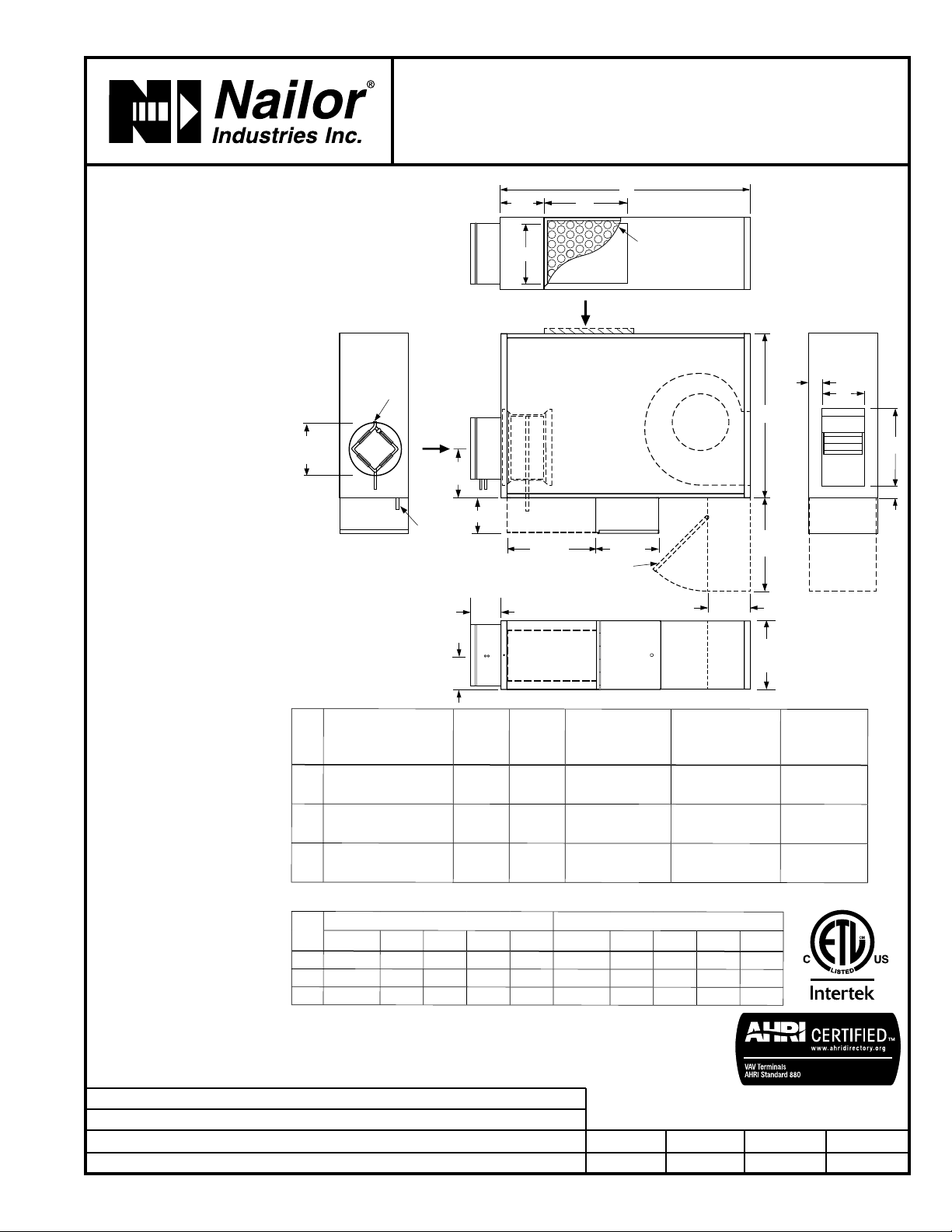
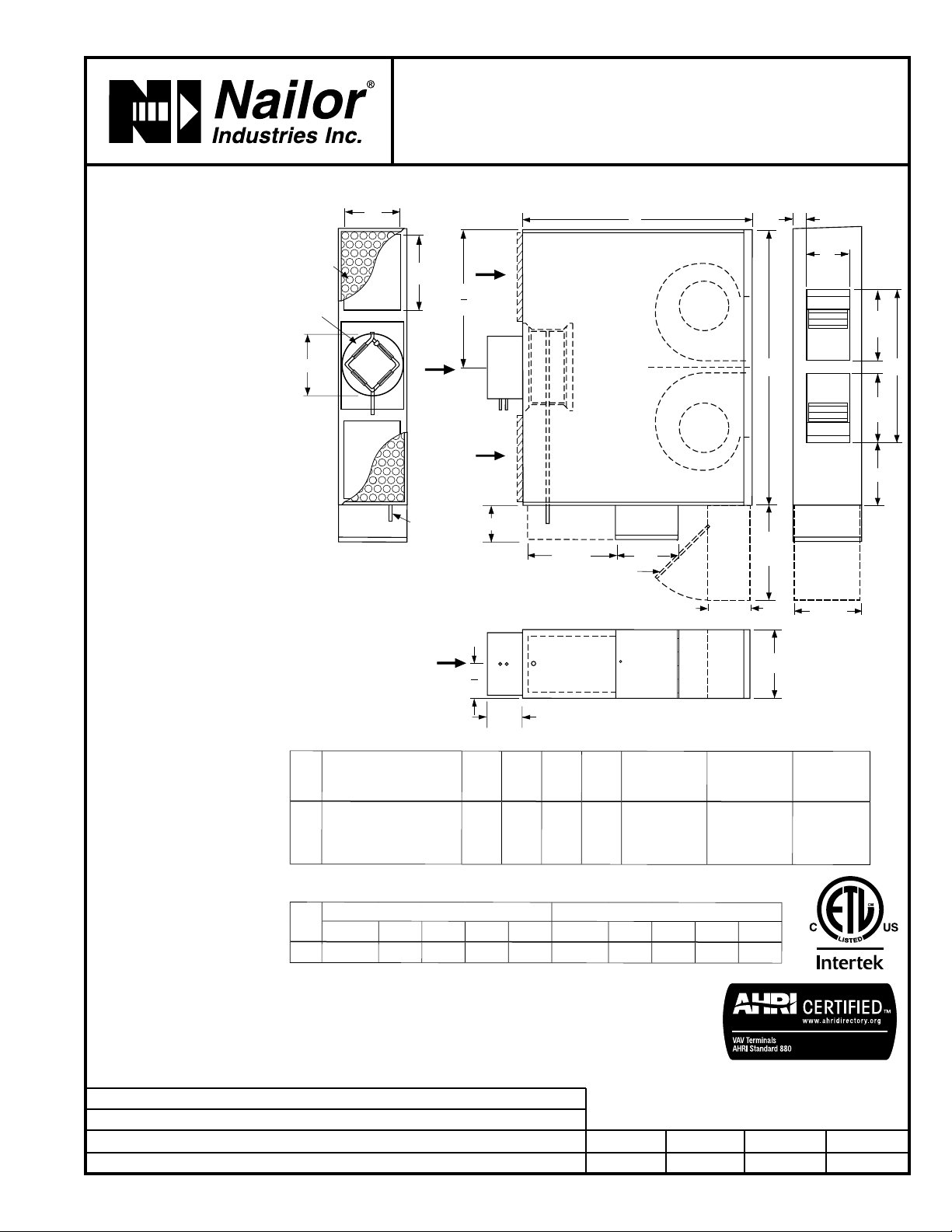
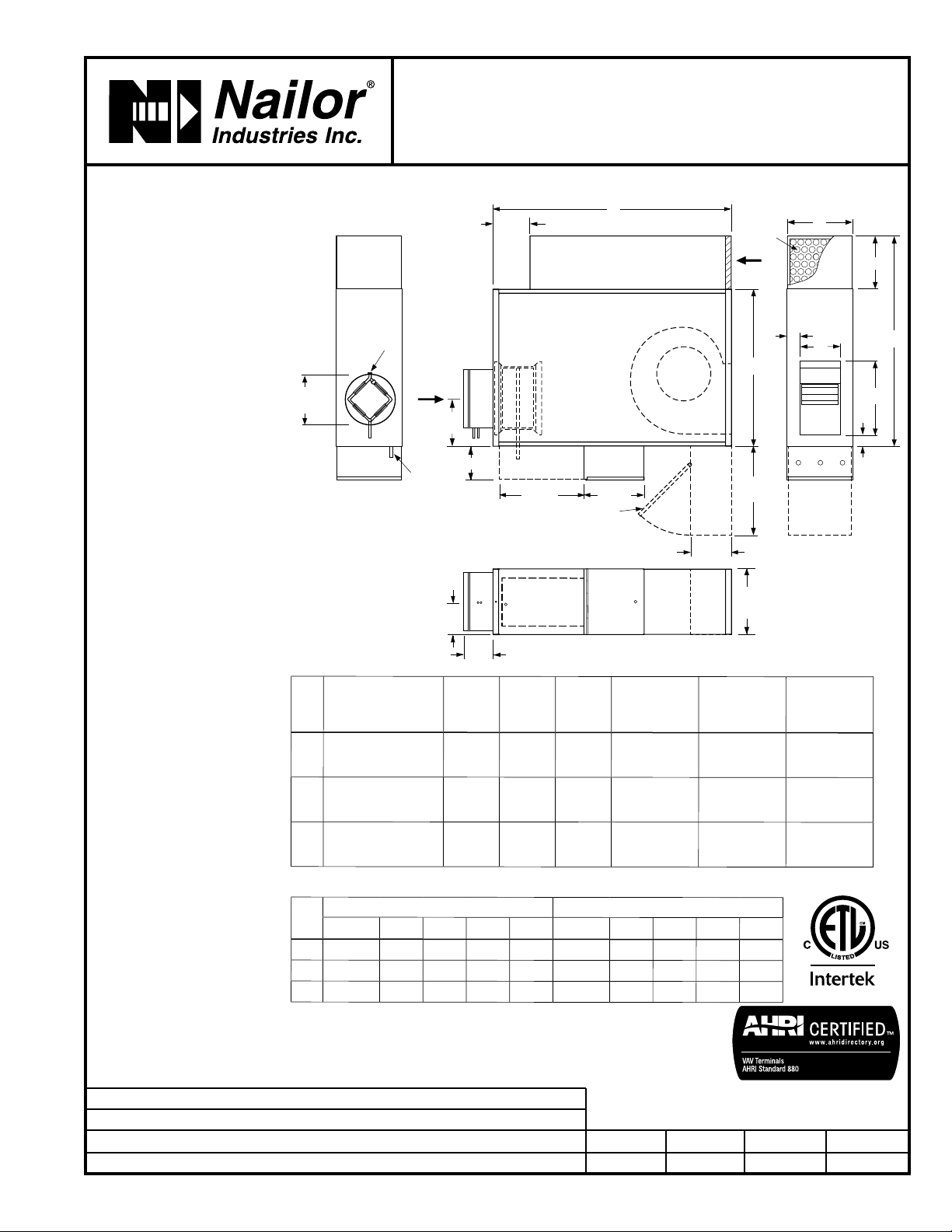
Dimensions are in inches (mm).
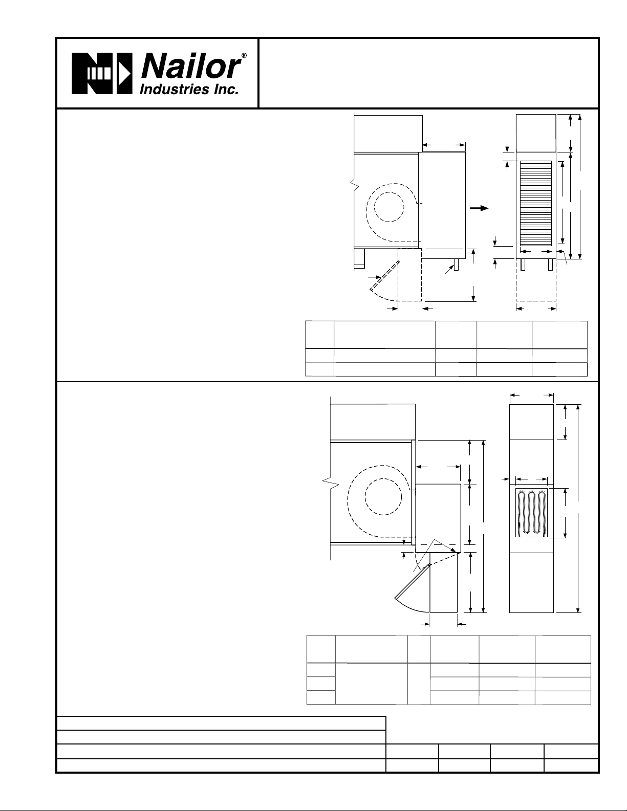
LOW PROFILE FAN POWERED TERMINAL UNIT WITH
EPIC ECM OR PSC MOTOR • HEAT ACCESSORIES
'STEALTHTM' • SERIES FLOW
CONSTANT OR VARIABLE VOLUME
MODELS: 37SWST AND 37SEST • UNIT SIZES 1 – 3
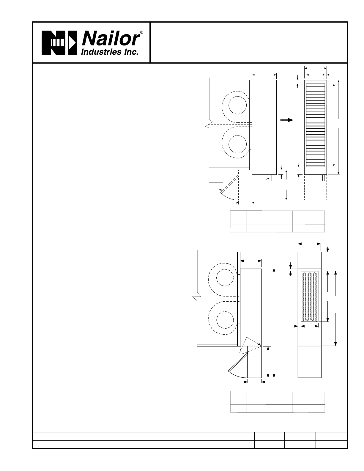
q Hot Water Coil Section Model 37SWST
Standard Features:
• Coil section installed on unit discharge.
• Coil (and header on multi-circuit units) is installed in insulated
casing for increased thermal efficiency.
• 1/2" (13) copper tubes.
• Aluminum ripple fins.
• Sweat connections: One row 1/2" (13) O. D. male solder. Two
and three row 7/8" (22) O.D. male solder.
• Top and bottom access panels for inspection and coil cleaning.
• Flanged outlet duct connection.
Coil Rows:
q1-Row q2-Row q3-Row
Coil Hand Connections:
(Looking in direction of airflow).
q Right hand (illustrated). Standard.
qLeft hand (terminals are inverted). Optional.
Connections must be selected same
hand as controls enclosure location.
q Electric Coil Section Model 37SEST
Standard Features:
• Controls enclosure incorporates a hinged access door opening
upstream that helps ensure NEC clearance requirements
and reduces footprint. (FN2 90° design is standard).
• Unique hinged heater design permits easy access, removal and
replacement of heater element without disturbing ductwork.
• Class A 80/20 Ni/Cr wire.
• Coil installed on unit discharge.
• Insulated coil element wrapper.
• Automatic reset high limit cut-outs (one per element).
• Single point electrical connection (except 600V).
• Fan interlock relay or positive pressure airflow switch.
• Flanged outlet duct connection.
• Terminal unit with coil is ETL Listed as an assembly.
• Controls mounted as standard on RH side as shown.
Terminals ordered with LH controls (optional) are inverted.
Voltage:
Single phase, 60 Hz.
q 120V q208V q240V q277V
Three phase, 60 Hz.
q208V q480V (4 wire wye).
q600V (dual point connection). q _______________ .
12" (305)
COIL
CONNECTION
1 3/4"
(44)
3 5/8" (92) D
IW
CE
1 1/8"
(29)
11" (279)
6 3/4"
FANHOT
WATER
COIL
OPTIONAL
90° FN2
HIGNED FAN
CONTROLS
ENCLOSURE
15"
(381)
FAN
F
G
1"
(25)
K
15"
(381)
IW
6 3/4"
11 1/2"
(292)
HINGED FOR ELEMENT
REMOVAL
2" (51) ELECTRIC
COIL AND
90° FN2
HINGED FAN
CONTROLS
ENCLOSURE
(STANDARD)
15 3/8"
(391)
M
ELECTRIC
HEATER
Unit
Size
Outlet Duct Size
C x D IW W3 E
114 1/2 x 8 3/4 (368 x 222) 9 (229) 29 (737) 20 (508)
2, 3 24 x 8 3/4 (610 x 222) 12 (305) 41 3/8 (1051) 29 3/8 (746)
Unit
Size
Outlet Duct Size
F x G IW M W3 K
112 3/8 x 9
(314 x 229)
9
(229)
3 5/8 (92) 44 7/8 (1140) 35 7/8 (911)
211 1/8 (283) 52 1/2 (1334) 43 1/2 (1105)
311 1/8 (283) 52 1/2 (1334) 43 1/2 (1105)
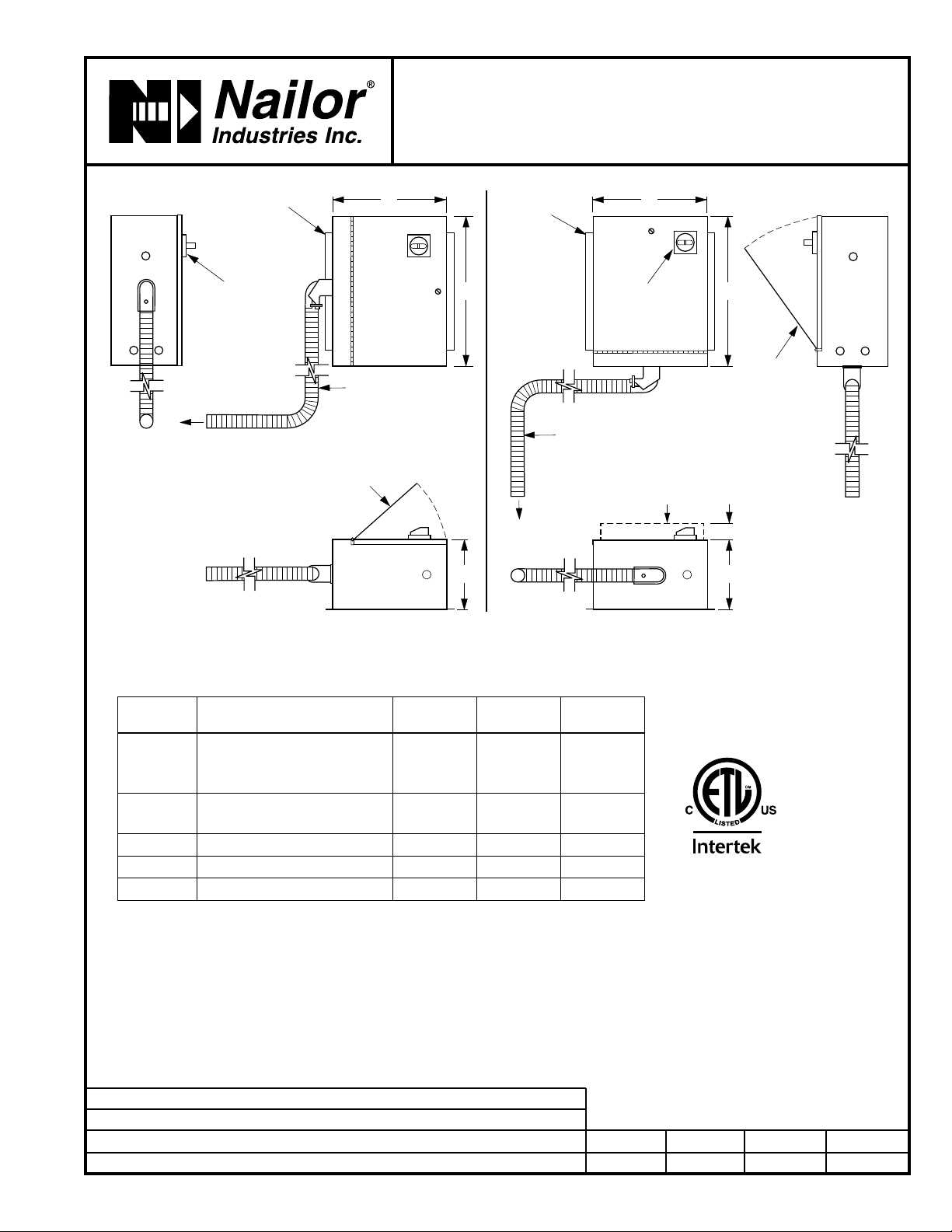
Options:
qToggle disconnect switch
(includes fan).
q SCR control.
qDoor interlock disconnect
switch.
qMercury contactors.
qPower circuit fusing.
qDust tight construction.
qManual reset secondary
thermal cut out.