Technogel Mixpasto 60 Operation instructions

Page 1 of 52
THIS MANUAL IS THE PROPERTY OF TECHNOGEL SpA–ALL REPRODUCTIONS, EVEN PARTIAL, ARE FORBIDDEN
1
CODE: xxxxxxxx EN
USE AND MAINTENANCE INSTRUCTIONS
Model: MIXPASTO 60/120
Serial No.: 00
Year of manufacture: 2013
Conformity:
TECHNOGEL SpA
Via Boschetti n°51
24050 GRASSOBIO (BG) –Italy
Tel. (+39) 035-4522062
Fax (+39) 035-4522682
www.technogel.com

Page 2 of 52
THIS MANUAL IS THE PROPERTY OF TECHNOGEL SpA–ALL REPRODUCTIONS, EVEN PARTIAL, ARE FORBIDDEN
2
INDEX
1 GENERAL WARNINGS AND STANDARDS
2 TECHNICAL FEATURES AND DATA
3 INSTALLATION
4 FUNCTIONING AND USE
5 USER INSTRUCTIONS
6 ROUTINE AND EXTRAORDINARY MAINTENANCE
7 DIAGNOSIS
8 ATTACHED DOCUMENTATION
1 - GENERAL WARNINGS
1.1 INTRODUCTION
The machine described in this manual is intended for professional use and must not be considered
as a household appliance: therefore, personnel in charge must be adequately trained.
Read the entire instructions manual before operating on the machine, in order to protect the operator and
avoid damaging the machine.
This manual must be fully integral and legible. All operators in charge of using the machine, the maintenance
or adjustment manager must know its location and be able to consult it at any moment.
TECHNLOGEL SpA reserves all reproduction rights for this manual.
This manual cannot be transferred to third party without TECHNOGEL SpA written authorisation.
The text cannot be used in other print-outs without TECHNOGEL SpA written authorisation.
The description and illustrations in this manual are not binding.
TECHNOGEL SpA reserves the right to make any changes it considers opportune.
THIS MANUAL IS THE PROPERTY OF TECHNOGEL SpA
ALL REPRODUCTIONS, EVEN PARTIAL, ARE FORBIDDEN
This manual was edited in accordance with Machinery Directive 2006/42/EC requirements.
1.2 METHODS OF CONSULTATION OF THE MANUAL
1.2.1 Structure of the manual
The manual is divided into chapters gathering all the necessary information for using the machine without
risks.
Each chapter is divided into paragraphs containing essential points. Each paragraph may have clarifications
entitled with a subtitle and a description.

Page 3 of 52
THIS MANUAL IS THE PROPERTY OF TECHNOGEL SpA–ALL REPRODUCTIONS, EVEN PARTIAL, ARE FORBIDDEN
3
Each chapter has a right page that recalls the number and title of the chapter.
A chapter, for example chapter 1, contains:
1 Heading of the chapter
1.1 Title of the paragraph
1.1.1 Heading of the subtitle
1.1.1.1 Any additional subtitle
The numbering of the figures and tables is reset at every chapter, therefore the progressive prefix indicating
the chapter and the number of the figure or table restarts from 1 at the beginning of each chapter.
1.2.2 Description of pictograms
The following symbols are used in the manual to highlight particularly significant indications and warnings:
ATTENTION:
This symbol shows accident-prevention standards for the operator and/or for any exposed people.
WARNING:
This symbol shows the existence of the possibility of damaging the machine and/or its components.
NOTE: This symbol provides useful information.
1.3 WARRANTY
The TECHNOGEL SpA manufactured machines are covered by WARRANTY, as provided by the general
selling conditions. In the event that defective or faulty machines parts are found during the validity period,
and when these parts are covered by the warranty, TECNOGEL SpA will repair or replace the part only after
having checked it with the distributor from whom the machine was purchased.
TECHNOGEL SpA considers itself responsible for the machine in its original configuration.
All interventions modifying the structure and functioning cycle of the machine must be expressly authorised
by TECHNOGEL SpA only.
All technical modifications affecting the functioning or safety of the machine must only be carried out by the
manufacturer's technical personnel or by its officially authorised technicians. If this is not the case,
TECHNOGEL SpA declines any liability for changes or damages that may derive there from.
TECHNOGEL SpA declines any liability for the machine improper use, for damages caused by operations
not addressed in this manual or unreasonable.
1.4 ARRANGEMENTS BY THE CUSTOMER
Detailed operating instructions are provided in chapter 3 of this manual (INSTALLATION).
A simple list of the arrangements by the customer is provided herein.
Except for specific contractual agreements, the following are the customer's responsibility:
- arrangement of premises (including masonry work, foundations or any requested channelling, etc.);
- arrangement of the place of installation and machine installation;
- arrangement of adequate auxiliary services for system requirements (e.g. water, electric mains, etc.);
Page 4 of 52
THIS MANUAL IS THE PROPERTY OF TECHNOGEL SpA–ALL REPRODUCTIONS, EVEN PARTIAL, ARE FORBIDDEN
4
R
24050 Grassobbio (BG) - ITALY
Website: www.technogel.com
Tel.: +39 035 4522062 - Fax: +39 035 4522682
ICE CREAM EQUIPMENT AND MACHINES
Via Boschetti, 51
E-mail: [email protected]
TIPO MACCHINA / Machine Type: MATRICOLA N° / Serial Number:
ANNO / Year:
ALIMENTAZIONE / Source:
QUANTITA' GAS / Gas Quantity:GAS FRIGORIGENO / Refrigerant:
CORRENTE P. C. / Full Load Current:
POTENZA / Power:
- any upstream and downstream safety devices of the energy power supply lines (such as residual-current
devices, earthing systems, safety valves, etc.) provided by the legislation in force in the country of
installation;
- tools and consumption materials required for assembly and installation;
- materials, tools and equipment required for any machine acceptance tests.
1.5 DECLARATION OF CONFORMITY
Attached to this manual.
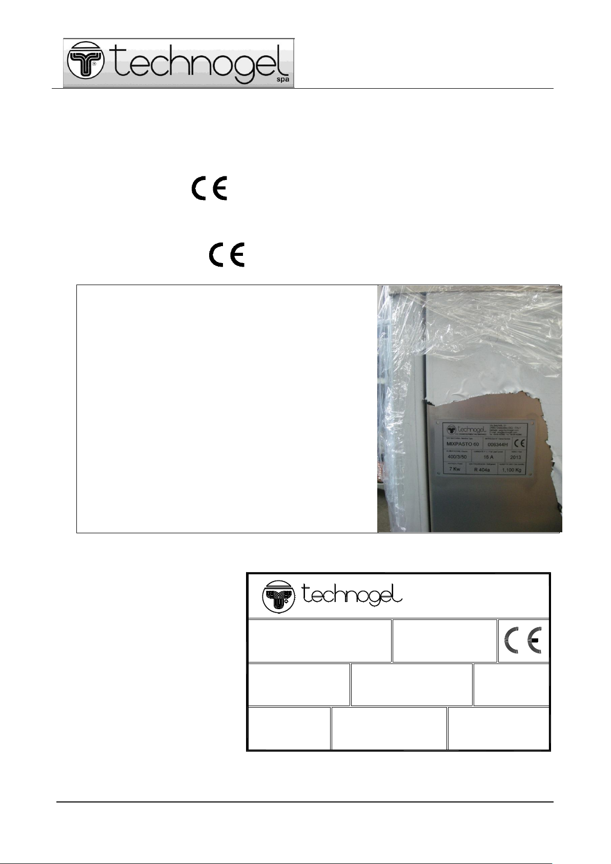
1.5.1 Identification plate
This machine is manufactured in an EU country and must,
therefore, meet the safety requirements of Machinery
Directive 2006/42/EC in force since 29 December 2009.
The EC Declaration of Conformity is attached to this
document.
This conformity is certified and the machine has the "EC"
marking on the support structure, as shown in figure 1-1.
The EC marking and data plate must not be removed or
damaged. It shows the data indicated in fig. 1-2:
Fig. 1-1 –Plate position
Fig. 1-2 –Data on the plate

Page 5 of 52
THIS MANUAL IS THE PROPERTY OF TECHNOGEL SpA–ALL REPRODUCTIONS, EVEN PARTIAL, ARE FORBIDDEN
5
1.6 INSTRUCTION FOR REQUESTING ASSISTANCE
Always state the following data whenever contacting the assistance centre:
- type of machine;
- serial number;
- year of manufacture;
- when possible, specify the nature of the detected machine problem or defect, e.g.: electric, mechanical
nature or in terms of processing quality.
Contact the technical assistance service through your area dealer or use the details in par. 2.2.
1.7 MACHINE DESCRIPTION
The MIXPASTO 60/120 PASTEURISER machine pasteurises mixes for ice cream by heating the products at
85° for high pasteurisation and break-down everything in the least possible time at 4°C.
The mix must then be preserved at 4°C to 6°C for the entire period of use that can be at a maximum of 72h.
The products are mixed during the process by means of a stirrer in tank that, based on the stirrer speeds
and shapes, favours the thermal exchange, gives consistency and different softness to the finished products.
The pasteurisation temperature can be lowered to 65°C depending on the ingredients, proportionally
extending the maintenance times to the temperature (low pasteurisation).
The machine consists of a 60 or 120 l tank protected by a transparent lid. The tank contains a motor-driven
stirrer and a pick-up cock on the bottom.
The machine heats the product through the circulation of a water and glycol mix heated at an adequate
temperature in a copper coil wrapped on the tank's outer surface. Cooling is through the circulation of freon
gas in another copper coil also wrapped on the tank's outer surface.
The water and glycol mix is heated by an armoured heater in a boiler and is pushed by a pump in the closed
circuit.
The water and glycol mix is pressurised in the circuit having an expansion vessel and safety valve (max 0.7
bar). The glycol temperature is electronically controlled by a safety thermostat that interrupts the heaters'
power supply if a safety temperature is exceeded (max 120°C).
Opening the lid interrupts stirring, isolating the motor's power supply, the heating/cooling and the glycol
circulation. The machine is ready to restart when the lid is closed. Opening the lid causes one or more
magnets to move away from the relative magnetic sensor that, in turn, switches off the relay and relative
contactors.
1.8 OPERATORS' QUALIFICATION
The operators and maintenance technicians in charge of machine functioning or maintenance must have the
specific professional requirements for every provided operation.
They must be trained and aware of the tasks entrusted to them.
WARNING
All technical modifications affecting the functioning or safety of the machine must only be
carried out by the manufacturer's technical personnel or by its officially authorised
technicians. On the contrary, TECHNOGEL SpA declines any liability for changes or damages
that may derive there from.

Page 6 of 52
THIS MANUAL IS THE PROPERTY OF TECHNOGEL SpA–ALL REPRODUCTIONS, EVEN PARTIAL, ARE FORBIDDEN
6
2 - TECHNICAL FEATURES AND DATA
2.1 TECHNICAL FEATURES
MIXPASTO 60
MIXPASTO 120
Dimensions and weight
Machine height
1060 mm
1060 mm
Machine length
1000 mm
1000 mm
Machine width
400 mm
640 mm
Overall weight
200 kg
275 kg
Product load with full load
60 litres
120 litres
Product load with reduced load
20 litres
40 litres
Performance/consumption
Average water consumption
300 l/h
500 l/h
Min pressure
0.15 MPa
0.15 MPa
Well water min temperature
5˚C
5˚C
Tower water max temperature
29˚C
29˚C
Cycle time with full load (*)
(*)
(*)
Tab. 2-1
(*) The value is subject to changes based on the type of processed mix, the volume, the surrounding
conditions, etc.
Electrical system
MIXPASTO 60
Power circuit
220 V
220 V
400 V
400 V
480V
Frequency
50 Hz
60 Hz
50 Hz
60 Hz
60Hz
Type of power supply
Three-
phase
Three-
phase
Three-
phase
Three-
phase
Three-
phase
Max absorbed power
7 kW
7 kW
7 kW
7 kW
7 kW
Max absorption
20 A
20 A
16 A
16 A
16 A
Section - line cable
4 x 4 mm²
4 x 4 mm²
5 x 2.5
mm²
5 x 2.5
mm²
5 x 2.5
mm²
MIXPASTO 120
Power circuit
220 V
220 V
400 V
400 V
Frequency
50 Hz
60 Hz
50 Hz
60 Hz
Type of power supply
Three-
phase
Three-
phase
Three-
phase
Three-
phase
Max absorbed power
13 kW
13 kW
13 kW
13 kW
Max absorption
35 A
35 A
24 A
24 A
Section - line cable
4 x 6 mm²
4 x 6 mm²
5 x 4 mm²
5 x 4 mm²

Page 7 of 52
THIS MANUAL IS THE PROPERTY OF TECHNOGEL SpA–ALL REPRODUCTIONS, EVEN PARTIAL, ARE FORBIDDEN
7
Tab. 2-2
2.2 MANUFACTURER DATA
Name: TECHNOGEL SpA
Registered office: Via Boschetti n°51
24050 GRASSOBIO (BG) –Italy
Tel. 035-4522062
Fax 035-4522682
www.technogel.com
Comp. Reg. Court of Bergamo No. 12583
E.A.I. of Bergamo No. 166982
VAT No. - Tax Code IT 00709420160
2.3 CHARACTERISTICS OF THE TREATED PRODUCT
The MIXPASTO 60/120 PASTEURISER is designed for preparing bases and mixes for the production of ice
cream, which recipe is the responsibility of the machine user.
The manufacturer only prescribes that the percentage of dry product in the mix be less than 42%.
2.4 NOISE
The noise level during normal functioning must never exceed 70 db(A).
2.5 ADMITTED ENVIRONMENTAL CONDITIONS
Install the machine in closed premises with adequate micro-climate for the presence of operators and
product processing.
Avoid atmospheres polluted by vapours or gas, float dust, bacterial loads, insects or anything else that might
endanger the product's hygienic conditions or the health of operators.
The rear part of the machine must be detached from wall or other impediments for sufficient air to circulate:
leave a space of at least 50 cm.
We recommend the work environment temperature to be below + 35°C, without direct exposure to sun and
to other heat sources.
ATTENTION
The machine is not designed to function in potentially explosive atmosphere.
Its installation and use in such environments is, therefore, forbidden.
3 - INSTALLATION
3.1 GENERAL SAFETY WARNINGS
•Wear suitable protective equipment for the operations to be carried out.
Clothing must adhere to the body and resist to cleaning products.

Page 8 of 52
THIS MANUAL IS THE PROPERTY OF TECHNOGEL SpA–ALL REPRODUCTIONS, EVEN PARTIAL, ARE FORBIDDEN
8
Avoid wearing ties, necklaces or belts that might get tangled between moving parts; wear a protective
helmet in case of lifting and transporting.
•When required, properly tie-up hair to avoid it getting tangled up between moving parts.
•Do not remove the safety devices or accident-prevention protections.
•Lift the machine and its components by carefully following the use and maintenance instructions, using an
adequate lifting mean with the utmost attention (for the weight, see paragraph 2.1 "Technical features").
•Do not dismantle machine units or parts without express authorisation and training.
•Make sure the used lifting means have an adequate capacity for the loads to be lifted and that they are in
good conditions (for the weight, see paragraph 2.1 "Technical features").
•Do not dismantle machine units or parts without express authorisation and training.
•Follow the environmental protection laws in force to dispose of the different packaging materials.
3.2 MACHINE TRANSPORT
ATTENTION
Purposely trained and authorised personnel must anchor the elements transported to the
transport mean.
WARNING:
The machine container must be protected during machine transport against atmospheric
agents using protective nylon to prevent water infiltrations and deposits on the elements in
question.
ATTENTION
The machine must be fastened to the platform or forklift truck forks using fastening
systems (belts or ropes) to avoid unbalances and falls.
The machine in question must be transported respecting the original packaging methods. It is necessary to
fasten the machine to the packaging sub-base (pallet with wooden crate) and protect the machine body
using the original packaging protections.
Where required, secure the machine container to the transport mean anchoring systems using belts with
adequate capacity to the weight to be secured.
The packaging is designed to perfectly protect the machine against impacts. Transport the packaged
machine as close as possible to the place of installation.
Insert the forks underneath the frame base of the machine where indicated to lift using forklift truck or
transpallet.
Pay the utmost attention in arranging the belts for lifting with crane or bridge-crane, in order to guarantee
machine stability during lifting; use belts with adequate capacity for insertion underneath the machine frame.
Pay proper attention in executing this operation to guarantee the required stability during machine handling.
Page 9 of 52
THIS MANUAL IS THE PROPERTY OF TECHNOGEL SpA–ALL REPRODUCTIONS, EVEN PARTIAL, ARE FORBIDDEN
9
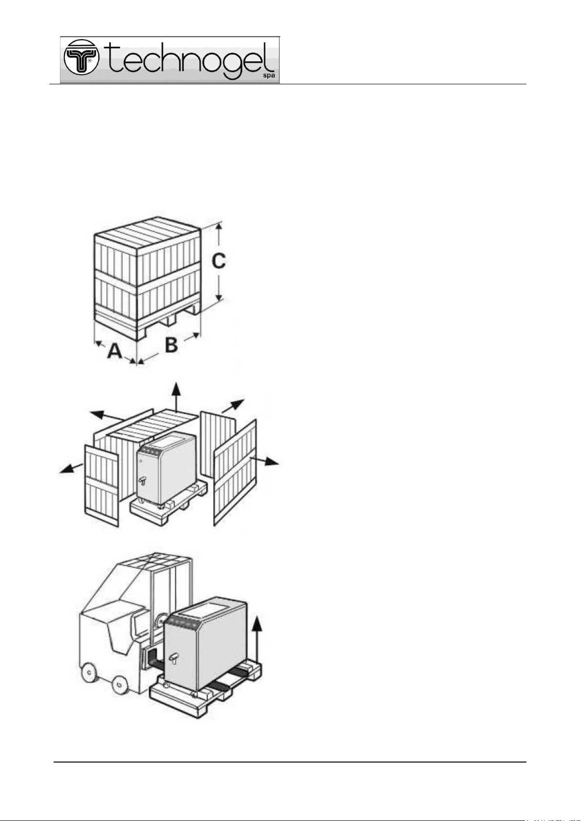
3.3 UNPACKING AND MACHINE HANDLING
Remove the packaging as follows:
MIXPASTO 60
GROSS WEIGHT = KG. 300
A = 650 mm
B = 1250 mm
C = 1600 mm
MIXPASTO 120
GROSS WEIGHT = KG. 375
A = 900 mm.
B = 1250 mm.
C = 1600 mm.
Remove all wooden side and top panels from the
packing.
Lift the machine using a fork-lift truck introducing the
lifting blades between the bottom of the machine
and the base of the crate.

Page 10 of 52
THIS MANUAL IS THE PROPERTY OF TECHNOGEL SpA–ALL REPRODUCTIONS, EVEN PARTIAL, ARE FORBIDDEN
10
Loosen the four bolts blocking the machine from
underneath the base of the crate.
ATTENTION:
After having remove the bolts the bottom of the
crate comes away from the machine bottom.
After having removed the crate bottom, lower the lift
and deposit the machine on the ground.
The machine can be moved by holding it from the
specific handles.
THE TYPE OF WOOD USED FOR THE PACKAGING CRATE IS NATURAL FIR
WITHOUT ANY CHEMICAL SUBSTANCE, THEREFORE PERFECTLY RECYCLABLE.
MIXTPASTO 60
NET WEIGHT = KG. 200
A = 400 mm.
B = 1000 mm.
C = 1060 mm.
MIXPASTO 120
NET WEIGHT = KG. 275
A = 640 mm.
B = 1000 mm.
C = 1060 mm
Lift the machine using a fork-lift truck introducing
the lifting blades at the side of the machine,
between the front and rear wheels.

Page 11 of 52
THIS MANUAL IS THE PROPERTY OF TECHNOGEL SpA–ALL REPRODUCTIONS, EVEN PARTIAL, ARE FORBIDDEN
11
Lift the machine using belts, holding them as in
figure near the front and rear wheels. The tie-rod
lifting the machine must position exactly at the
centre of the machine
Move the machine by holding it from the specific
handles
Once the machine is in position, block the front
wheels brakes using the feet
DO NOT USE HANDS!!
N.B.: Visually check the status of integrity. Contact the dealer or manufacturer in case of evident
damages.
Properly lift the machine from the base platform and use suitable means to extract the latter.
Careful not to damage the power supply cable. Avoid using ropes or chains that might damage the machine.
Now set the packaging materials aside and keep them for future transport.
The disposal operation is safe as the packaging is made of fully recycle material.
3.4 GENERAL NOTES ON THE FOUNDATION TECHNIQUES
The machine does not require particular foundation work. Make sure the support base where the machine
will be installed is flat, stable and able to support its weight.
It is fitted with wheels that cannot be adjusted in height; the front wheels can be blocked with brake and the
rear are swivel and cannot be blocked.
Page 12 of 52
THIS MANUAL IS THE PROPERTY OF TECHNOGEL SpA–ALL REPRODUCTIONS, EVEN PARTIAL, ARE FORBIDDEN
12
3.5 INSTALLATION
The following rules must be respected during installation:
Placement
Place the machine onto a flat and solid surface.
Avoid the direct exposure to sunbeams and nearby heat sources.
Leave at least 50 cm of free space in front of the grids to enable the perfect functioning of the refrigeration
system.
Set-up
The machine is supplied with all its parts permanently installed.
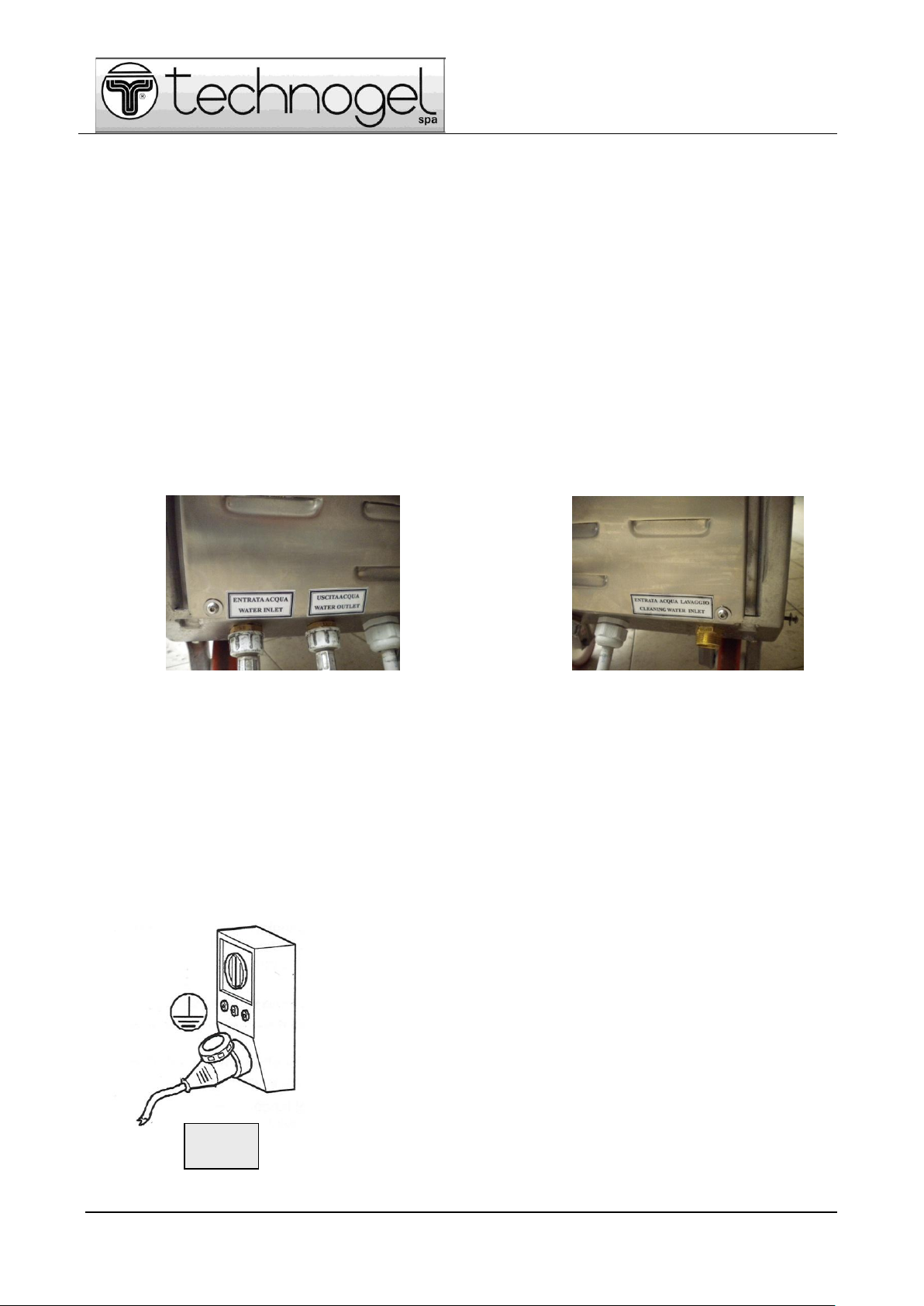
Connection to water mains
Connect the water piping of the cooling circuit to the fittings accessible from the rear of the machine and
identified by the specific wording (see Fig. 3.2a).
Use water from the well or the mains with temperature below 30°C. The guaranteed flow rate must be 500
l/h. The machine pressure valve regulates the flow of the condenser's cooling water.
Then connect the water pipe for washing hand shower (fig. 3.2b)
Fig. 3.2a Fig. 3.2b
Connection to electric mains
The power supply system must have a 5-pole socket for 3N three-phase power supply for 400 V and at 4-
poles 3F for 220 V voltages of approved type.
The current socket must be protected by a type B residual current device calibrated at 300 mA, by a circuit
breaker suitable for the currents indicated in tab. 2.1, and be equipped with earth connection.
Check the mains voltage and frequency correspond to those required by the machine, indicated on the EC
plate or technical manual.
Connect the machine using the power plug to the power supply. This must be close and easily accessible
and managed by the operator
A main switch must be provided in the socket or in an easily accessible place, that completely disconnects
voltage from the socket (isolation) and enables the interaction or execution of operations requiring access to
moving parts (see fig. 3.3.).
The electrical system for powering the machine must be perfect.
The manufacturer is not liable for inadequate power supply and
earthing system and/or non-conform to standards.
Only enabled personnel can connect the electrical parts.
Fig. 3.3

Page 13 of 52
THIS MANUAL IS THE PROPERTY OF TECHNOGEL SpA–ALL REPRODUCTIONS, EVEN PARTIAL, ARE FORBIDDEN
13
3.6 DEMOLITION AND DISPOSAL
With regard to demolishing and disposal, remember that the materials constituting the machine are not
dangerous and mainly consist of:
- stainless steel
- copper
- plastic materials (polycarbonate, various isolators, etc.)
- refrigerant gas R404A
- glycol
- electric motors;
- electric cables with relative sheaths.
ATTENTION
Evacuate and dispose of the materials from the machine demolition by following the
relative standards in force for the protection of the environment.
Take the necessary precautions to prevent the dispersion of refrigerant gas from the
cooling system into the air. This operation must be carried out by authorised personnel,
following the procedures approved by the public authority.
3.6.1 Procedure for dismantling the machine
Proceed as follows should it be necessary to dismantle the machine for its demolition:
•Consult the environmental protection laws in force in the user's country.
•As legally prescribed, activate the inspection procedure by the Body in charge and the consequent
reporting of the demolition.
•Group and separate the components according to their chemical nature.
•Proceed with the scrapping in respect of the laws in force in the user's country.
•During dismantling, carefully comply with the health and safety prescriptions of the operators.
ATTENTION
Dismantling must be carried out by qualified personnel.
ATTENTION
Different legislations are in force in different countries. Observe the prescriptions set by
the laws and the bodies in charge in the countries where the demolition occurs.

Page 14 of 52
THIS MANUAL IS THE PROPERTY OF TECHNOGEL SpA–ALL REPRODUCTIONS, EVEN PARTIAL, ARE FORBIDDEN
14
4 - FUNCTIONING AND USE
4.1 DESCRIPTION OF THE FUNCTIONING
4.1.1 Description of controls
The machine controls are placed on its front panel in an ergonomically comfortable position for the operator
to access it.
The operator has direct access to the machine.
"START" KEY
Pressing this button switches on the machine placing it in "STAND-BY"
while awaiting further commands. The pressed button remains on (green
light). This button is used to switch-off the equipment in any functioning
cycle mode, with machine on.
The controls are located on the control panel (DISPLAY) enabling the interaction with the micro-processor
controlling machine functioning.
Fig. 4.1 –Control panel
1 - ARROW KEY

Page 15 of 52
THIS MANUAL IS THE PROPERTY OF TECHNOGEL SpA–ALL REPRODUCTIONS, EVEN PARTIAL, ARE FORBIDDEN
15
Enables moving the display cursor upwards.
2 - HOSE SPRAY KEY
Pressing this key opens the timed passage (3 minutes) of the washing water in the manual hose spray.
The water flow is controlled by an hold-down lever of the tap.
3 - ARROW KEY
Enables moving the display cursor downwards.
4 - STIRRER KEY
When pressed it starts the stirrer functioning without heating or cooling phases. It is always active except
when the automatic cycle is started or during the refrigerator phase.
5 - CYCLE START KEY
Pressing this key starts the automatic functioning cycle.
6 - ARROW KEY
Enables moving the display cursor upwards.
7 - ENTER KEY
Enables confirming the command selected in the chosen menu.
8 - ARROW KEY
Enables moving the display cursor downwards.
9 - REFRIGERATOR CYCLE KEY
Enables immediately starting the refrigerator cycle without waiting for the times provides by the automatic
cycle. It is also active when not in cycle and enables reaching the permanent temperature of 4÷6 °C, at least
for as long as the START button is on (machine electrically powered).
10 - STOP KEY
Stops the cycle and brings the machine back in stand-by, without guaranteed temperature specifications.
4.1.2 Operating phases
The MIXPASTO 60/120 is intended for the pasteurisation of mixes for ice cream with heating and cooling
cycles controlled by a micro-processor programmable by the user.
The machine provides the following operative treatment phases for the ice cream mix:
1. pasteurisation
2. emulsifying
3. cooling
4. preservation (maturation)
Emulsifying happens by increasing the stirrer speed in view of the product temperature and by making the
product bang against the metal elements of a specifically designed grid.
The stirrer speeds are pre-set. There are normally 2 speeds set during heating and 2 during cooling; the
speed automatically changes when the mix reaches 55°C, both during heating and during cooling.
The user can request the setting of 3 speeds both during heating and during cooling, from the manufacturer's
Technical Service.
The stirrer speed is further reduced during preservation and it automatically intervenes for 1 minute at
intervals of 20 minutes.
The user can ask the manufacturer's Technical Service to set the functioning times of the stirrer during
preservation differently.
The operator can vary the stirrer speed at any moment by means of the LEFT ARROWS.
The cycle times in the chart of fig. 4.2 refer to laboratory tests with specific products that can differ based on
the type of mix and functioning conditions (environment temperature, water temperature, etc.).

Page 16 of 52
THIS MANUAL IS THE PROPERTY OF TECHNOGEL SpA–ALL REPRODUCTIONS, EVEN PARTIAL, ARE FORBIDDEN
16
Fig. 4.2
The "bain-marie" method is used with the product tray wrapped by a coil in which a heat-transmitting fluid
(glycol+water) flows.
The product is loaded from above by lifting the polycarbonate lid; discharge is through the tap located in the
front part of the machine.
The user decides the composition of the mix to be pasteurised: the percentage of the dry part (the density of
the mix) can influence the outcome of the cycle: it must not, however, exceed the limit of 42%.
ATTENTION
The machine must never operate empty!
4.1.3 Use of commands
The machine is powered by connecting its plug to the mains; it does not have a main switch.
Pressing the START button activates the electric power supply. The control panel's screen switches on (see
fig. 4.1) and show the installed SW + HW upgrade index.
The user interacts with the machine micro-processor by means of the commands shown in fig. 4.1, that is:
- the screen
- the buttons.

Page 17 of 52
THIS MANUAL IS THE PROPERTY OF TECHNOGEL SpA–ALL REPRODUCTIONS, EVEN PARTIAL, ARE FORBIDDEN
17
The user can select the entries of the different MENUS through the left arrows:
when the wanted entry is highlighted (lights-up), it is automatically selected.
The user can vary the value of a parameter using the right arrows (increase = top
arrow; decrease = bottom arrow)
It enables selecting the entry or value chosen by the user
Pressing the STIRRER key
opens the specific menu with
the spiral symbol. The bottom
of the screen shows the time in
progress (left) and the set time
(right).
The stirrer speed can be
increased or decreased with the
LEFT ARROWS.
Pressing the REFRIGERATOR
key opens a specific menu with
the snow-flake symbol. The
stirrer speed can be increased
or decreased with the LEFT
ARROWS.
The current product
temperature, that drops to 4°C
(refrigerator preservation),
appears at the bottom of the
screen.
The user, in addition to the buttons, can use the commands selected on the control panel screen.
The interface between user and machine consists in a series of MENUS with which the operator can set the
wanted functioning.
Use the LEFT ARROWS to select "ESC" (top-left of each screen) followed by ENTER, to exit each menu: the
previous menu is in this way accessed.
Page 18 of 52
THIS MANUAL IS THE PROPERTY OF TECHNOGEL SpA–ALL REPRODUCTIONS, EVEN PARTIAL, ARE FORBIDDEN
18
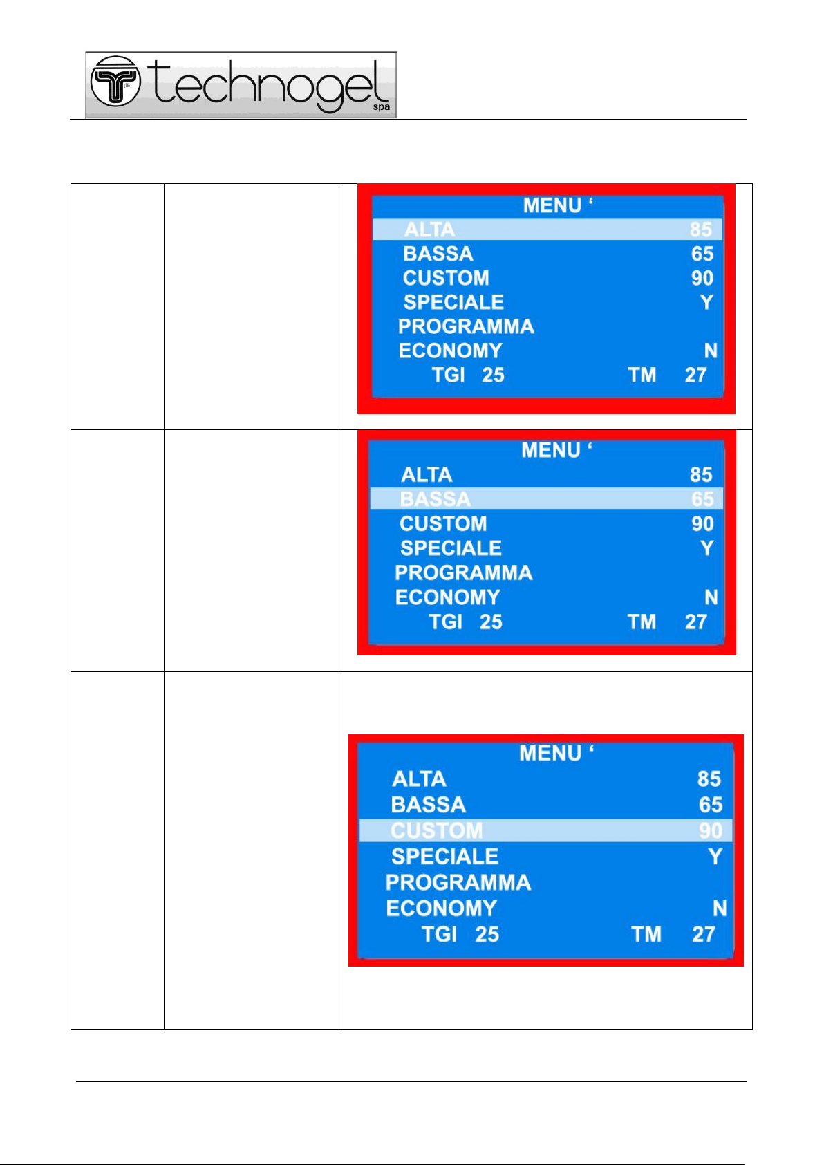
Press ENTER (7, fig. 4.1) after having switched on the panel: the screen shows the machine main menu composed as
follows:
HIGH
High pasteurisation cycle,
with heating at 85°C
followed by cooling at 4°C
LOW
Low pasteurisation cycle,
with heating at 65°C,
maintenance for 30 minutes,
followed by quick cooling at
4°C
CUSTOM
Cycle the user can
customise by selecting the
temperature from 60°C to
90°C. This cycle is required
as some ingredients are
sensitive to high
temperatures. The user can
select the different menus
entries using the left arrows
(pos. 6 and 8, fig. 4.1). The
wanted entry is
automatically selected when
highlighted (lit-up).
Using the left arrows (pos. 1
and 3, fig. 4.1) the
"Temperature" in the
CUSTOM cycle can be
varied (the Temperature in
the HIGH and LOW cycles is
fixed). The micro-processor
automatically defines the
Maintenance in temperature
time before quick cooling,
that is the same for all cycle
types.
Page 19 of 52
THIS MANUAL IS THE PROPERTY OF TECHNOGEL SpA–ALL REPRODUCTIONS, EVEN PARTIAL, ARE FORBIDDEN
19
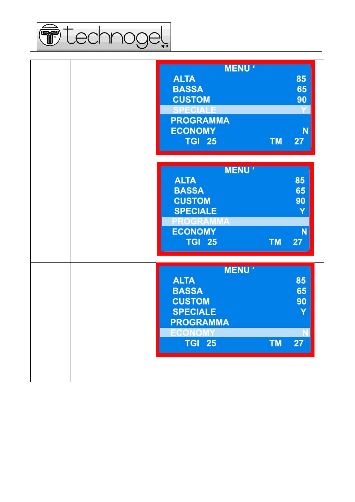
SPECIAL
Special programs pre-set by
the user can be selected
following the methods
explained in par. 4.1.4.
Once the entry is selected,
use the RIGHT ARROWS to
select one of the 5 special
programs the user can set
(see par. 4.1.4) namely:
YOGHURT Y
CHOCOLATE C
PROGRAM P1
PROGRAM P2
PROGRAM P3
PROGRAM
Press ENTER to access the
next menu for setting the
special programs as
required by the user (see
par. 4.1.4)
ECONOMY
This program enables using
the half tank load cycles:
use the 20 to 40 l program
for the "60" machine; the 40
to 100 l for the "120".
Once the entry is selected
set "Y" (YES) or "N" (NO)
using the RIGHT KEYS.
This is the first parameter to
be set when the machine
production cycle is started,
before setting the above
cycles.
TM
The current temperature of
the mix always appears
bottom-right of the main
menu.

Page 20 of 52
THIS MANUAL IS THE PROPERTY OF TECHNOGEL SpA–ALL REPRODUCTIONS, EVEN PARTIAL, ARE FORBIDDEN
20
Press the "CYCLE START" key (pos. 2, fig. 4.1) to
start the machine, after having selected the wanted
cycle.
The thermometer symbol appears on the screen if
the program provides a heating phase; the snow
crystal symbol appears if it provides a cooling
phase.
The stirrer speed can be increased or decreased
with the LEFT ARROWS.
4.1.4 Cycle programming
The operator can pre-set 5 customised programs for each of which the process parameters must be fixed.
Select PROGRAM from the main menu and press ENTER: the next menu
appears providing 5 rows (see figure at side), to each of which corresponds one of
the special programs.
It is possible to customise one of the 5 programs indicated on screen:
YOGHURT Y
CHOCOLATE C
PROGRAM P1
PROGRAM P2
PROGRAM P3
Every program is structured in 6 steps or operating phases.
Every step can be set as heating or cooling phase (RAMP) or as maintenance in
constant temperature phase (STOP).
Select the chosen program using the LEFT ARROWS and then ENTER
(e.g. program Y: the menu relating to STEP 1 appears.
Select the T RAMP entry using the RIGHT ARROWS: when highlighted,
the T RAMP and T STOP entries alternate using the LEFT ARROWS.
The user chooses the type of phase to be attributed to the STEP in
question, then press ENTER to acquire the setting.
This manual suits for next models
1
Table of contents
Other Technogel Commercial Food Equipment manuals

Popular Commercial Food Equipment manuals by other brands


Diamond
Diamond AL1TB/H2-R2 Installation, Operating and Maintenance Instruction

Salva
Salva IVERPAN FC-18 User instructions

Allure
Allure Melanger JR6t Operator's manual

saro
saro FKT 935 operating instructions

Hussmann
Hussmann Rear Roll-in Dairy Installation & operation manual

Cornelius
Cornelius IDC PRO 255 Service manual

Moduline
Moduline HSH E Series Service manual

MINERVA OMEGA
MINERVA OMEGA DERBY 270 operating instructions

Diamond
Diamond OPTIMA 700 Installation, use and maintenance instructions

Diamond
Diamond G9/PLCA4 operating instructions

Cuppone
Cuppone BERNINI BRN 280 Installation

Arneg
Arneg Atlanta Direction for Installation and Use