Technogym ACTIVE Wellness TV RUN EXCITE User manual

ACTIVE
Wellness TV
15” Display – RUN EXCITE
Machine configuration


Contents
1. MACHINE CONFIGURATION...............................................................................................1
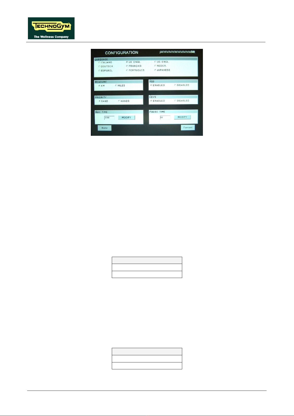
1.1. User menu configuration.................................................................................................................................... 1
1.1.1. SN..............................................................................................................................................................2
1.1.2. Language...................................................................................................................................................2
1.1.3. Measure.....................................................................................................................................................2
1.1.4. Priority......................................................................................................................................................2
1.1.5. Maximum excercise time...........................................................................................................................3
1.1.6. Enable TGS ...............................................................................................................................................3
1.1.7. Keys...........................................................................................................................................................3
1.1.8. Pause time.................................................................................................................................................3
1.1.9. Top exercise programs for you shortcut....................................................................................................4
1.1.10. Modifiable target heart rate......................................................................................................................4
1.1.11. Standby......................................................................................................................................................4
1.1.12. Language...................................................................................................................................................5
1.1.13. Enable up/down motor ..............................................................................................................................5
1.1.14. User detect.................................................................................................................................................5
1.1.15. Default config............................................................................................................................................6
1.1.16. Format P&P..............................................................................................................................................6
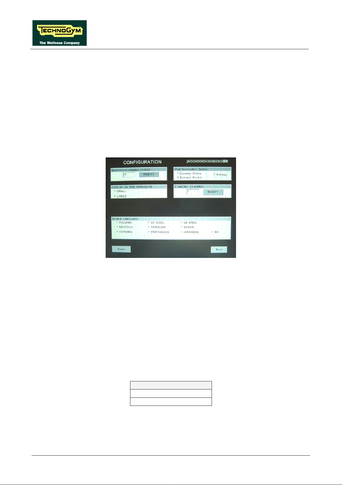
1.1.17. Screen saver minutes.................................................................................................................................6
1.1.18. Display in the workout ..............................................................................................................................6
1.1.19. iPod connection option..............................................................................................................................7
1.1.20. Standby channel ........................................................................................................................................7
1.1.21. Other language..........................................................................................................................................7
1.2. Service menu configuration ............................................................................................................................... 8
1.2.1. Low kit parameter .....................................................................................................................................9
1.2.1.1. Read from low kit............................................................................................................................................................. 9
1.2.1.2. Write to low kit ................................................................................................................................................................9
1.2.1.3. Default Setting.................................................................................................................................................................. 9
1.2.1.4. Table of configuration parameters...................................................................................................................................9
1.2.2. Operating data ........................................................................................................................................10
1.2.2.1. Read from low kit........................................................................................................................................................... 10
1.2.2.2. Write to low kit ..............................................................................................................................................................10
1.2.3. Errors log................................................................................................................................................11
1.2.3.1. Read from low kit........................................................................................................................................................... 11
1.2.3.2. Reset Errors.................................................................................................................................................................... 11
1.2.3.3. COM.Fault...................................................................................................................................................................... 11
1.2.4. TV Standard.............................................................................................................................................13
1.2.5. SW version devices..................................................................................................................................13
1.2.6. Mains voltage..........................................................................................................................................14
1.2.7. Standard settings.....................................................................................................................................14
1.2.8. Read/Write registers................................................................................................................................14
1.2.8.1. Read from low kit........................................................................................................................................................... 14
1.2.8.2. Write to low kit ..............................................................................................................................................................14
1.2.9. UpDown settings .....................................................................................................................................18
1.2.9.1. Read from low kit........................................................................................................................................................... 19
1.2.9.2. Write to low kit ..............................................................................................................................................................19
1.2.9.3. Default Setting................................................................................................................................................................19
1.3. Inverter autotuning .......................................................................................................................................... 19
1.4. Recall parameters ............................................................................................................................................. 20
1.5. Default parameters ........................................................................................................................................... 20
1.6. TV menu configuration for 700i E models ..................................................................................................... 21
1.6.1. Tuning TV channels.................................................................................................................................21
1.6.2. Wellness TV adjustments.........................................................................................................................23
1.7. Radio menu configuration for 700i E models................................................................................................. 24
1.7.1. Tuning radio channels.............................................................................................................................24
1.7.1.1. Automatic radio channel tuning procedure.................................................................................................................... 25
1.7.1.2. Procedure for manually entering radio channel frequencies.........................................................................................26
1.8. Transferring the tuning data ........................................................................................................................... 27
1.8.1. Using the TGS .........................................................................................................................................27

1.8.2. Using the connecting cable .....................................................................................................................27
1.9. Touch screen calibration.................................................................................................................................. 28
1.10. Troubleshooting service menu for 700 and 900 models................................................................................. 30
1.10.1. I2C Device Test.......................................................................................................................................31
1.10.2. CSafe COM test.......................................................................................................................................31
1.10.3. Low Kit COM Test...................................................................................................................................31
1.10.4. TGS COM Test........................................................................................................................................31
1.10.5. UpDown Test...........................................................................................................................................32
1.10.6. Inverter Test ............................................................................................................................................32
1.10.7. Manual Inverter Test...............................................................................................................................32
1.10.8. Manual UpDown Test .............................................................................................................................32

ACTIVE WTV: Machine configuration
1. MACHINE CONFIGURATION
1.1. USER MENU CONFIGURATION
The machine configuration procedure is invoked, when the machine is in standby mode, by pressing
the top right hand, the bottom left hand and the bottom right hand corner in sequence, as shown in
the picture below.
The machine display will shows a window from where you can access the different configuration
menus, using the proper password.
To access the menu, type in the password 2406 and press ENTER key to confirm or BACK key to
back forward.
At this point the machine display will shows the different parameters of the menu, collected in
different pages, which can be scrolled with the FORWARD and BACK keys.
To exit the configuration press HOME key.
Pressing “HOME” in any page, all changes made up to that moment are saved; you
cannot exit without saving. In case of errors the initial Technogym settings can be
restored using the “DEFAULT CONFIG.” parameter.
Here below have been detailed all the parameters of the menu.
Page 1

ACTIVE WTV: Machine configuration
Page 2
1.1.1. SN
In the top right hand corner of the windows it is displayed the SN of the machine, loaded at the end
of the production line.
1.1.2. LANGUAGE
After selecting a language from the list of those available, all messages subsequently displayed by
the machine will be in the chosen language. To change the selection, select the desired option
among the ones in the list, directly touching on the Touch Screen.
Press HOME to confirm and save, FORWARD or BACK to scroll the pages.
1.1.3. MEASURE
It is possible to choose between EUROPEAN units (kg and km) or IMPERIAL units (pounds and
miles). To change the selection, select the desired option among the ones in the list, directly
touching on the Touch Screen.
MEASURE
KM <default>
MILES
Press HOME to confirm and save, FORWARD or BACK to scroll the pages.
1.1.4. PRIORITY
If signals are available from both the chest band and hand sensors, this parameter determines which
is the preferential source for displaying the heart rate value. Obviously, if only one of these two
signals is available, it will be used even if not configured as the preferential heart rate source. To
change the selection, select the desired option among the ones in the list, directly touching on the
Touch Screen.
PRIORITY
BAND <default>
HANDS
Press HOME to confirm and save, FORWARD or BACK to scroll the pages.

ACTIVE WTV: Machine configuration
1.1.5. MAXIMUM EXCERCISE TIME
It is possible to set a maximum duration for the exercise in minutes, with a value ranging from 1 to
9999. To change the setting, press the MODIFY key and insert the value using the numeric
keyboard. Press ENTER key to confirm or BACK key to back forward.
The default value of this parameter is 9999.
Press HOME to confirm and save, FORWARD or BACK to scroll the pages.
1.1.6. ENABLE TGS
It is possible to enable or disable the use of the TGS reader. To change the selection, select the
desired option among the ones in the list, directly touching on the Touch Screen.
TGS
ENABLED <default>
DISABLED
Press HOME to confirm and save, FORWARD or BACK to scroll the pages.
1.1.7. KEYS
It is possible to disable the keyboard so that the machine can only be used with the TGS. To change
the selection, select the desired option among the ones in the list, directly touching on the Touch
Screen.
KEYS
ENABLED <default>
DISABLED
Press HOME to confirm and save, FORWARD or BACK to scroll the pages.
1.1.8. PAUSE TIME
It is possible to set a maximum pause time for each exercise in seconds, with values ranging from
10 to 999. To change the setting, press the MODIFY key and insert the value using the numeric
keyboard. Press ENTER key to confirm or BACK key to back forward.
The default value of this parameter is 60.
Press HOME to confirm and save, FORWARD or BACK to scroll the pages.
Page 3

ACTIVE WTV: Machine configuration
Page 4
1.1.9. TOP EXERCISE PROGRAMS FOR YOU SHORTCUT
It is possible to choose 2 extra training programs, from the list of those available, which will be
displayed in the main page with the fixed ones “TIME” and “CALORIES”. To change the selection,
select the desired option among the ones in the list, directly touching on the Touch Screen.
TOP EXERCISE PROGRAMS
FOR YOU SHORTCUT
DISTANCE
TRAINING ZONE
CUSTOM OPACE
CPR
PRESET PROFILES
FITNESS TEST
WEIGHT LOSS
CUSTOM SPEED
Press HOME to confirm and save, FORWARD or BACK to scroll the pages.
1.1.10. MODIFIABLE TARGET HEART RATE
It is possible to enable or disable modification of the target heart rate during a constant heart rate
exercise. To change the selection, select the desired option among the ones in the list, directly
touching on the Touch Screen.
HR
MODIFIABLE <default>
NOT MODIFIABLE
Press HOME to confirm and save, FORWARD or BACK to scroll the pages.
1.1.11. STANDBY
It is possible to enable or disable the TV screen during the standby mode. To change the selection,
select the desired option among the ones in the list, directly touching on the Touch Screen.

ACTIVE WTV: Machine configuration
STANDBY
TV ON <default>
TV OFF
Press HOME to confirm and save, FORWARD or BACK to scroll the pages.
1.1.12. LANGUAGE
The machine can be configured to allow selection of the language at each session. To change the
selection, select the desired option among the ones in the list, directly touching on the Touch
Screen.
LANGUAGE
FIXED <default>
OPTIONAL
Press HOME to confirm and save, FORWARD or BACK to scroll the pages.
1.1.13. ENABLE UP/DOWN MOTOR
This parameter enables or disables use of the machine incline. To change the selection, select the
desired option among the ones in the list, directly touching on the Touch Screen.
UP-DOWN
ENABLED <default>
DISABLED
Press HOME to confirm and save, FORWARD or BACK to scroll the pages.
1.1.14. USER DETECT
This function is able to detect the presence of a user running on the tread belt during an exercise
session. It is possible to configure a minimum speed at which the machine will determine that the
user has stopped running on the treadmill, and interrupt the exercise session if the condition persists
for one minute.
To change the setting, press the MODIFY key and insert the value using the numeric keyboard.
Press ENTER key to confirm or BACK key to back forward.
The default value of this parameter is 5.0 km/h or 3 mph/h.
The minimum threshold speed for the user detect function is 3.0 km/h or 2.0 mph/h.
Entering any value lower than this will have the effect of disabling the user-detect
function.
Entering any value of the user weight lower than 50 Kg during the configuration of the
exercise, will have the effect of disabling the user-detect function.
Press HOME to confirm and save, FORWARD or BACK to scroll the pages.
Page 5

ACTIVE WTV: Machine configuration
Page 6
1.1.15. DEFAULT CONFIG
It is possible to reset the user menu parameters to their default values. To select the function, press
on “DEFAULT CONFIG” key.
Press HOME to confirm and save, FORWARD or BACK to scroll the pages.
1.1.16. FORMAT P&P
This function formats a TGS key for Plug&Play mode operation. To select the function, press
“FORMAT P&P” key.
Press HOME to confirm and save, FORWARD or BACK to scroll the pages.
1.1.17. SCREEN SAVER MINUTES
It is possible to configure the amount of time, in minutes, the machine will wait before activating
the screen saver, with values ranging from 10 to 360.
To change the setting, press the MODIFY key and insert the value using the numeric keyboard.
Press ENTER key to confirm or BACK key to back forward.
The default value of this parameter is 10.
Press HOME to confirm and save, FORWARD or BACK to scroll the pages.
1.1.18. DISPLAY IN THE WORKOUT
It is possible to configure the size of the exercise data during the workout. To change the selection,
select the desired option among the ones in the list, directly touching on the Touch Screen.
DISPLAY IN THE WORKOUT
SMALL <default>
LARGE
Press HOME to confirm and save, FORWARD or BACK to scroll the pages.

ACTIVE WTV: Machine configuration
1.1.19. IPOD CONNECTION OPTION
It is possible to set the machine for controlling the iPod through the display. To change the
selection, select the desired option among the ones in the list, directly touching on the Touch
Screen.
IPOD CONNECTION OPTION
DOCKING STATION <default>
NOTHING
External Pocket -not used-
Press HOME to confirm and save, FORWARD or BACK to scroll the pages.
1.1.20. STANDBY CHANNEL
It is possible to set the channel which is displayed on the TV, when the TV is in standby. To change
the setting, press the MODIFY key and insert the value using the numeric keyboard. Press ENTER
key to confirm or BACK key to back forward.
Press HOME to confirm and save, FORWARD or BACK to scroll the pages.
1.1.21. OTHER LANGUAGE
It is possible to set a shortcut for a second language different from the one set at “LANGUAGE”
parameter, displayed in the top left hand corner of the main page.
To change the selection, select the desired option among the ones in the list, directly touching on
the Touch Screen.
Press HOME to confirm and save, FORWARD or BACK to scroll the pages.
Page 7

ACTIVE WTV: Machine configuration
Page 8
1.2. SERVICE MENU CONFIGURATION
The machine configuration procedure is invoked, when the machine is in standby mode, by pressing
the top right hand, the bottom left hand and the bottom right hand corner in sequence, as shown in
the picture below.
The machine display will shows a window from where you can access the different configuration
menus, using the proper password.
To access the menu, type in the password 2501 and press ENTER key to confirm or BACK key to
back forward.
At this point the machine display will shows the different parameters of the menu, collected in
different pages, which can be scrolled with the FORWARD and BACK keys.
To exit the configuration press HOME key.
Pressing “HOME” in any page, all changes made up to that moment are saved; you
cannot exit without saving. In case of errors the initial Technogym settings can be
restored using the “STANDARD SETTINGS.” parameter.
Here below have been detailed all the parameters of the menu.

ACTIVE WTV: Machine configuration
1.2.1. LOW KIT PARAMETER
This function provides access to parameters used for modifying certain settings of the lower
assembly. To access this menu, when the display shows:
In addition to the 13 configuration parameters, this function also includes the 3 sub-functions
described below:
1.2.1.1. Read from low kit
To read the parameter values from the low kit memory and view them on the display, press READ
FROM LOW KIT key.
1.2.1.2. Write to low kit
To write the values of the currently displayed parameters to the low kit, press WRITE TO LOW
KIT key.
1.2.1.3. Default Setting
To load the default parameter values, press DEFAULT SETTING key.
1.2.1.4. Table of configuration parameters
To correctly display the parameter values, you need to load them from the low kit, using
the “Read from low kit” function.
Parameter Description Range Default value
Par 01 Default speed for Quick Start workout.
[Km/h*10] 0 - 300 8
Par 02 Default acceleration and deceleration for tread
belt motor. [Km/h*100/sec] 0 - 3000 100
Par 03 Default zero reference position for tread-belt
incline. [*2] -10 - +40 0
Par 04 PID proportional gain. [*100] 0 - 9999 7
Par 05 PID Integral gain. [*100] 0 - 9999 150
Par 06 Ramp Type 0 - 100 0
Par 07 Error status on DC motor encoder 0 - 1 0
Par 08 Serial communication timeout [10*msec] 0 - 255 0
Page 9

ACTIVE WTV: Machine configuration
Page 10
Parameter Description Range Default value
Par 09 DC motor encoder error timeout. [msec] 0 - 255 15
Par 10 FREE - 0
Par 11 Driving roller diameter. [mm] 0 - 1000 91
Par 12 Pulley ratio 0 - 9000 200
Par 13 Error status on AC motor encoder 0 - 1 0
To change the setting, press the CHANGE key and insert the value using the numeric keyboard.
Press ENTER key to confirm or BACK key to back forward.
After any changes to the parameter values, you need to load them in the low kit using
the “Write to low kit” function.
Press HOME to confirm and save, FORWARD or BACK to scroll the pages.
1.2.2. OPERATING DATA
This function makes it possible to access the machine usage data stored in the low kit.
In addition to the machine usage data, this function also includes the 2 sub-functions described
below:
1.2.2.1. Read from low kit
To read the parameter values from the low kit memory and view them on the display, press READ
FROM LOW KIT key.
1.2.2.2. Write to low kit
To write the values of the currently displayed parameters to the low kit, press WRITE TO LOW
KIT key.
The machine usage data on the display is updated every 10 minutes. This means that, whenever the
machine is switched off, any data modified after the last memory update will be lost.
To correctly display the parameter values, you need to load them from the low kit, using
the “Read from low kit” function.

ACTIVE WTV: Machine configuration
MESSAGE ON DISPLAY DESCRIPTION
Life AC M: Minutes x 10 of tread belt motor operation
Life DC M: Minutes of elevation motor operation
Life Kit H: Minutes x 10 of operation of the upper assembly
Life Kit L: Minutes x 10 of operation of the lower assembly
Tot. Km: Total km travelled
By pressing the RESET key on the side of the value, it is possible to reset the value of the selected
item.
Press HOME to confirm and save, FORWARD or BACK to scroll the pages.
1.2.3. ERRORS LOG
This function accesses the machine’s error history log.
In addition to the error history log, this function also includes the 3 sub-functions described below:
1.2.3.1. Read from low kit
To read the parameter values from the low kit memory and view them on the display, press READ
FROM LOW KIT key.
1.2.3.2. Reset Errors
To clear the error history in both the low and high kit memory, press RESET ERRORS key.
1.2.3.3. COM.Fault
This is a counter that display the number of errors in serial communication between the upper and
the lower kit. This counter increase each time a communication fault is detected.
To reset this counter, press RESET key on the side of the value.
To correctly display the parameter values, you need to load them from the low kit, using
the “Read from low kit” function.
For every error generated by the machine, the error history log records the information in the table
below:
• Counter
• Error code
• Current when the error occurred
• Distance in km when the error occurred
The correspondence between error codes and descriptions is given in the table below:
Page 11

ACTIVE WTV: Machine configuration
Page 12
Error
code
Error
number Description
OH 1 Overheating of the heat sinks of the AT drive and of the PFC.
OC 2 Overcurrent, even if only transient, on the inverter output.
UU 3 Undervoltage condition, due to an even transient drop in line voltage.
OU 4 Overvoltage.
PE 6
EEPROM error. Is generated when there is an error detected in the data
stored on the EEprom.
EdC1 7 Elevation motor encoder error.
EdA 8 AC motor encoder error.
OtM 9 AC motor thermal cutout open.
Oli 10
Inverter overload caused by a DC current exceeding, for the maximum
allowed time (I2t), the maximum permissible threshold for the inverter.
OLm 11
Motor overload caused by a DC current exceeding, for the maximum
allowed time (I2t), the maximum permissible threshold for the motor in
question.
OLr 12 Braking resistor overload.
Ot 13
Over-torque due to an even momentary overload of the inverter. Is
generated when the torque output of the motor exceeds a pre-established
limit for a pre-established time.
OCH 16 HW overcurrent.
MST 17
Motor lockout which occurs, operating in closed loop mode with the
encoder active, if the inverter fails to reach the target speed even after
attempting to reduce the reference frequency.
EM 19
Emergency. Is generated when the AT drive receives a software
emergency signal that is not accompanied by a hardware emergency
signal.
SHC 23
Short Circuit. Is generated in the event of a short circuit between a motor
phase and earth.
Press HOME to confirm and save, FORWARD or BACK to scroll the pages.

ACTIVE WTV: Machine configuration
1.2.4. TV STANDARD
This function allows to display/configure the TV Standard on the machine. To change the selection,
select the desired option among the ones in the list, directly touching on the Touch Screen.
NTSC M NTSC44 M PAL B/G PAL I PAL D/K
SECAM D/K SECAM L SECAM L1 PAL B/H PAL M
SECAM H SECAM B/G PAL N
Selected as a function of the country where the machine is installed according to the following
table:
Multistandard
code
TG
code
TV Standard Countries
Albania Australia Austria Baharain Belgium
Cameroon Croatia Cyprus Czech Rep Denmark
Finland Germany Ghana Greece Hungary
India Israel Italy Jordan Kenya
Luxembourg Malaysia Malta Netherlands New Zealand
Nigeria Norway Pakistan Poland Portugal
Romania Singapore Slovakia Slovenia Spain
Sri Lanka Sweden Switzerland Thailand Turkey
1 PAL B/G
United Arab E Zambia Zimbabwe
Botswana Hong Kong Ireland South Africa Seychelles
2 PAL I UK
5 SECAM E/L France
Bulgaria Estonia Ex URSS Latvia Lithuania
6 SECAM D/K Poland Russia Ukraina
8 PAL D/K Czech Rep China Poland
Saudi Arabia Iran Iraq Morocco Tunisia
9 SECAM B/G Syria
French Guyana Guadeloupe Madagascar Martinique New Caledonia
E
A SECAM K1 Senegal Togo Zaire
3 PAL N Argentina Paraguay Uruguay
Bahamas Bermuda Canada Chile Costa Rica
Guatemala Japan Korea Peru Philippines
4 NTSC
Taiwan Trinidad USA Venezuela
7 NTSC M44 Mexico
U
B PAL M Brazil
Press HOME to confirm and save, FORWARD or BACK to scroll the pages.
1.2.5. SW VERSION DEVICES
This function allows to display:
• the display SW version;
• the low kit SW version (H:x L:x B:x);
• the key reader SW version.
Page 13

ACTIVE WTV: Machine configuration
Page 14
AT drivers for European and US market, use the same SW, nevertheless the first
character among the three which identify the SW version, changes according to the HW
mounted on the machine. In particular you can find:
• 2.x.x if the AT driver on the machine is that for European market.
• 4.x.x if the AT driver on the machine is that for US market.
Press HOME to confirm and save, FORWARD or BACK to scroll the pages.
1.2.6. MAINS VOLTAGE
This function allows the user to choose the proper power supply voltage for the machine. To change
the selection, select the desired option among the ones in the list, directly touching on the Touch
Screen.
No set
100 VAC
120 VAC
230 VAC
Choosing “No set” value, each time the machine is switched on it is necessary to insert the power
supply voltage provided by the electrical mains line.
1.2.7. STANDARD SETTINGS
This function clears the operating data of the machine and simultaneously resets the User menu, low
kit, UpDown table parameters to their default values. To launch the values restore press
STANDARD SETTINGS key
This function does not alter the language and the TV standard setting.
1.2.8. READ/WRITE REGISTERS
This function allows to display/modify the parameter values of type b, C, D, F, P, H and S. To
access this menu.
To correctly display the parameter values, you need to load them from the low kit, using
the “Read from low kit” function.
In addition to the machine usage data, this function also includes the 2 sub-functions described
below:
1.2.8.1. Read from low kit
To read the parameter values from the low kit memory and view them on the display, press READ
FROM LOW KIT key.
1.2.8.2. Write to low kit
To write the values of the currently displayed parameters to the low kit, press WRITE TO LOW
KIT key.

ACTIVE WTV: Machine configuration
Press the ADDRESS key, insert the desired address and press ENTER to confirm and display the
parameter value. Press BACK key to back forward.
Press the VALUE key, insert the correct value and press ENTER to confirm the new parameter
value. Press BACK key to back forward.
Although the changes made to the parameters come into effect immediately, they are not
automatically stored in permanent memory; this requires a specific write operation
effected using the command C-0: at address 800 write the value “1”.
To return to the upper menu level press CLEAR for a few seconds.
MENU –A–
Par. AddressDescription Value Par. AddressDescription Value
PID mode (700/900) 1 A-59 1218PID min neg err 50
A-0 1200PID mode (500) 0 A-100 1219Set Linear speed 0
A-1 1201PID ref sel 5 A-101 1220Set Acc Dec 100
A-2 1202PID fbk sel 4 A-102 1221Set Incline ref 0
A-3 1203PID digital ref 0 A-105 1222Def Linear speed 8
A-4 1204PID activat mode 0 A-106 1223Def Acc Dec 100
A-5 1205PID-Encoder sync 1 A-107 1224Def Incline ref 0
A-6 1206PID err sign rev 0 A-110 1225Pulley Ratio 200
A-7 1207PID Integ init en 0 A-111 1226Roller Diameter 91
A-8 1208PID update time 0
A-50 1209PID Prop gain 1 7 A-115 1227DCMot EncTimeout
(AT driver SW ≥2.07)15
A-51 1210PID Int tconst 1 150 A-116 1228Fan command dly 3
A-52 1211PID Deriv gain 1 0 50
A-53 1212PID Prop gain 2 0 A-117 1229ACMot EncToller 0(OFF)
A-54 1213PID Int tconst 2 9999 A-118 1230Check RunnerBand 10
A-55 1214PID Deriv gain 2 0 A-119 1231Check RunnerSpd 50
A-56 1215PID high limit 80 A-120 1232Curr clamp thr 200
A-57 1216PID low limit -80 A-121 1233Check RunnerDly 60
A-58 1217PID max pos err 50
MENU –C–
Par. Address Description Value Par. Address Description Value
C-0 800 Save parameters 0 C-41 805 Save pars to key 0
C-1 801 Recall param 0 C-100 806 Measure stator R 0
C-2 802 Load default 0 C-200 807 Reset AC Flag 0
C-20 803 Alarm clear 0 C-201 808 Reset DC Flag 0
C-40 804 Recall key prog 0
MENU –D–
Par. Address Description Value Par. Address Description Value
D-0 1 Output frequency 0 D-200 26 An in 1 cnf mon 0
D-1 2 Frequency ref 0 D-201 27 An in 1 monitor 0
D-2 3 Output current 0 D-202 28 An in 1 term mon 0
D-3 4 Output voltage 0 D-210 29 An in 2 cnf mon 0
D-4 5 DC link voltage 400 D-211 30 An in 2 monitor 0
D-5 6 Power factor 100 D-212 31 An in 2 term mon 0
D-6 7 Power [kW] 0 D-220 32 An in 3 cnf mon 0
D-7 8 Output speed 0 D-221 33 An in 3 monitor 0
Page 15

ACTIVE WTV: Machine configuration
Page 16
MENU –D–
Par. Address Description Value Par. Address Description Value
D-8 9 Speed ref 0 D-222 34 An in 3 term mon 0
D-20 57 Actual speed 0 D-300 35 EncPulse/Sample 0
D-21 58 Actual incline user 0 D-301 36 Encoder freq 0
D-22 59 Actual ENC1 pos 0 D-302 37 Encoder speed 0
D-23 60 Crossed distance 0 D-350 38 Option 1 state 0
D-24 61 Reserved - D-351 39 Option 2 state 0
D-25 62 Flag status 0 D-352 40 Par port state 0
D-26 63 Actual ENC2 pos 0 D-400 41 PID reference 0
D-27 64 Actual speed from
Fenc 0 D-401 42 PID feedback 0
D-30 70 Reserved - D-402 43 PID error 0
D-50 10 Heatsink temp 0 D-403 44 PID integr comp 0
D-51 11 Drive OL 0 D-404 45 PID output 0
D-52 12 Motor OL 0 D-800 46 Error 1 0
D-53 13 Brake res OL 0 D-801 47 Error 2 0
D-100 14 Dig inp status 0 D-802 48 Error 3 0
D-101 15 Term inp status 0 D-803 49 Error 4 0
D-102 16 Vir dig inp stat 0 D-950 50 Drive rated cur 100
D-120 17 Exp dig inp stat 0 D-951 51 SW version 1\2 200h
D-121 18 Exp term inp 0 D-952 52 SW version 1\2 80h
D-122 19 Exp Vir dig inp stat 0 D-953 53 power ident code 0h
D-150 20 Dig out status 0 D-954 54 param ident code 0h
D-151 21 Drv dig out sta 0 D-955 55 regul ident code 3/8h
D-152 22 Vir dig out sta 0 D-956 56 Startup id code 0h
D-170 23 Exp Dig out status 0 D-957 71 Drive type 2
D-171 24 Exp Drv dig out sta 0 D-999 99 Display test -
D-172 25 Exp Vir dig out sta 0
MENU –F–
Par. Address Description Value Par. Address Description Value
F-0 300 Motorpot ref 0 F-110 321 Frequency ref 10 0
F-10 301 Acc/Dec time mp 50 F-111 322 Frequency ref 11 0
F-11 302 Motorpot offset 0 F-112 323 Frequency ref 12 0
F-12 303 Mp output mode 0 F-113 324 Frequency ref 13 0
F-13 304 Mp auto save 1 F-114 325 Frequency ref 14 0
F-20 305 Max ref freq 1150 F-115 326 Frequency ref 15 0
F-21 306 Min ref freq 0 F-116 327 Jog frequency 10
F-50 307 Ref 1 channel 8 F-200 328 Ramp resolution 0
F-51 308 Ref 2 channel 0 F-201 329 Acc time 1 3000
F-60 309 MltFrq channel 1 3 F-202 330 Dec time 1 3000
F-61 310 MltFrq channel 2 3 F-203 331 Acc time 2 50
F-100 311 Frequency ref 0 0 F-204 332 Dec time 2 50
F-101 312 Frequency ref 1 0 F-205 333 Acc time 3 50
F-102 313 Frequency ref 2 0 F-206 334 Dec time 3 / FS 50
F-103 314 Frequency ref 3 0 F-207 335 Acc time 4 / Jog 50
F-104 315 Frequency ref 4 0 F-208 336 Dec time 4 / Jog 50
F-105 316 Frequency ref 5 0 F-250 337 Ramp S-shape 0
F-106 317 Frequency ref 6 0 F-260 338 Ramp extens src 0
F-107 318 Frequency ref 7 0 F-270 339 Jump amplitude 0
F-108 319 Frequency ref 8 0 F-271 340 Jump frequency 1 0
F-109 320 Frequency ref 9 0 F-272 341 Jump frequency 2 0
Table of contents
Other Technogym Fitness Electronic manuals