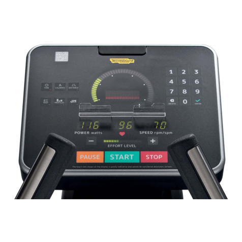
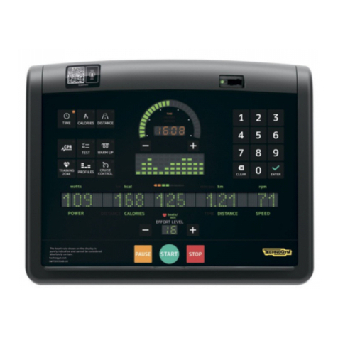
Technogym ISOCONTROL User manual

SERVICE & MAINTENANCE MANUAL
REV. 1.2


The information contained in this manual is intended for QUALIFIED TECHNICIANS who have
completed a specific TECHNOGYM training course and are authorized to perform machine start-
up and adjustment procedures as well as extraordinary maintenance or repairs which require a
thorough knowledge of the machine, its operation, its safety devices and working procedures.
CAREFULLY READ THE INFORMATION CONTAINED IN
THIS MANUAL BEFORE PERFORMING ANY MAINTENANCE
PROCEDURES ON THE MACHINE
DANGEROUS VOLTAGES
PRESENT EVEN WHEN THE
MACHINE IS TURNED OFF
NOTE
The information contained in this document is subject to change without notice.
Technogym does not guarantee this documentation in any way. Technogym shall not be held
responsible for any errors contained in this manual and declines all liability for accidents or
damages resulting from the supply, characteristics and use of this manual.
This document contains proprietary information that is protected by copyright. All rights reserved.
No part of this document may be photocopied, reproduced or translated into another language
without the prior written consent of Technogym.
Technogym™ is a registered trademark of Technogym S.p.A.
Isocontrol™ is a registered trademark of mywellness.com™ S.p.A.


ISOCONTROL: Service & Maintenance Manual - rev. 1.2
Pagina i
Contents
AVVERTENZE GENERALI................................................................................................................................1.1
1INTRODUCTION.................................................................................................................................................1.1
2RECOMMENDATIONS ........................................................................................................................................1.1
3GENERAL RULES FOR REPAIR PROCEDURES ......................................................................................................1.2
TECHNICAL CHARACTERISTICS..................................................................................................................2.1
1MECHANICAL CHARACTERISTICS .....................................................................................................................2.1
2ELECTRICAL CHARACTERISTICS .......................................................................................................................2.1
3AMBIENT SPECIFICATIONS................................................................................................................................2.1
4CONFORMITY TO REGULATIONS........................................................................................................................2.1
5PRODUCT CODE ................................................................................................................................................2.2
6WIRING DIAGRAM ............................................................................................................................................2.3
6 1
Wiring...................................................................................................................................................2.4
PRINCIPLES OF OPERATION..........................................................................................................................3.1
1BLOCK DIAGRAM .......................................................................................................................................3.1
1 1
Display panel .......................................................................................................................................3.1
1 2
Encoder board......................................................................................................................................3.2
1 3
Power supply........................................................................................................................................3.2
ACCESSORI..........................................................................................................................................................4.1
1SERIAL CABLE FOR PC CONNECTION................................................................................................................4.1
2ELECTRICAL CONNECTION................................................................................................................................4.2
2 1
Direct connection.................................................................................................................................4.2
2 2
Daisy chain...........................................................................................................................................4.2
INSTALLATION INSTRUCTIONS....................................................................................................................5.1
1SPECIFICATIONS AND REQUIREMENTS ..............................................................................................................5.1
2INSTALLATION..................................................................................................................................................5.1
2 1
Preparing Selection machines frames that require drilling.................................................................5.2
2 2
Procedure for Selection machines........................................................................................................5.3
221 Templates for Selection machine frames which require drilling....................................................................................5.6
222 Pulleys to replace on Selection machines.......................................................................................................................5.9
2 3
Preparing Element machines frames that require drilling.................................................................5.14
2 4
Procedure for Element machines.......................................................................................................5.20
241 Template for Element machine frames which require drilling.....................................................................................5.24
3FIRST POWER-ON......................................................................................................................................5.25
TROUBLESHOOTING......................................................................................................................................6.27
1TEST PROCEDURE ...........................................................................................................................................6.28
1 1
LED Test.............................................................................................................................................6.28
1 2
Encoder test........................................................................................................................................6.28
2THE DISPLAY FAILS TO ILLUMINATE .................................................................................................6.29
3THE ROM IS NOT READ OR IS READ INCORRECTLY.........................................................................................6.31
4THE MACHINE DOES NOT READ THE TGS..........................................................................................6.35
DISASSEMBLY OF COMPONENTS.................................................................................................................7.1
1DISASSEMBLING THE DISPLAY..........................................................................................................................7.1
2DISASSEMBLING THE DISPLAY COMPONENTS...................................................................................7.2
3DISASSEMBLING THE ENCODER BOARD ON SELECTION MACHINES ....................................................7.3
4DISASSEMBLING THE ENCODER BOARD ON ELEMENT MACHINES.......................................................7.4
ADJUSTMENTS....................................................................................................................................................8.1

ISOCONTROL: Service & Maintenance Manual - rev. 1.2
Pagina ii
MACHINE CONFIGURATION..........................................................................................................................9.1
1SERVICE MENU CONFIGURATION ......................................................................................................................9.1
1 1
Machine code .......................................................................................................................................9.1
1 2
Rom range............................................................................................................................................9.2
1 3
Start position........................................................................................................................................9.2
1 4
Pacer speed..........................................................................................................................................9.3
1 5
Time-out di attesa del cambio lato.......................................................................................................9.4
1 6
Enabling TGS messages.......................................................................................................................9.2
1 7
LED Test...............................................................................................................................................9.2
1 8
Encoder test..........................................................................................................................................9.2
181 Machines with 1 encoder board (all Element machines, for Selection machines refer to paragraph 5.2.2.2 “Pulleys to
replace on Selection machines”.)....................................................................................................................................9.2
182 Machines with 2 encoder boards (refer to paragraph 5.2.2.2 “Pulleys to replace on Selection machines”.)................9.3
1 9
Saving the configuration ......................................................................................................................9.3
2USER MENU CONFIGURATION ................................................................................................................9.4
2 1
Configuring the TGS key......................................................................................................................9.4
3LANGUAGE...................................................................................................................................................9.5
SCHEDULED MAINTENANCE.......................................................................................................................10.1
1EXTERNAL CLEANING OPERATIONS ................................................................................................................10.1
1 1
Setting up the operation .....................................................................................................................10.1
1 2
Cleaning operations...........................................................................................................................10.1
2SPECIAL MAINTENANCE OPERATIONS .............................................................................................................10.2
2 1
Setting up the operation .....................................................................................................................10.2
2 2
Cleaning operations...........................................................................................................................10.2
2 3
Checking the wiring and connections ................................................................................................10.2
2 4
Checking the display ..........................................................................................................................10.2
2 5
Functional check of components........................................................................................................10.2

ISOCONTROL: Service & Maintenance Manual - rev. 1.2
Pagina 1.1
1. AVVERTENZE GENERALI
1.1. INTRODUCTION
This document is reserved for Technogym Service technicians, and is intended to provide
authorized personnel with the necessary information to correctly carry out repairs and maintenance.
A thorough knowledge of the technical information contained in this manual is essential for
completing the professional training of the operator.
In order to facilitate consultation, the paragraphs are accompanied by schematic illustrations
highlighting the topic covered.
This manual contains notices and symbols which have a specific meaning:
WARNING: non observance may result in accident or injury.
ATTENTION: non observance may cause damage to the machine.
Information about the operation in progress.
OBSERVE: observation about the operation in progress.
1.2. RECOMMENDATIONS
Technogym recommends the following steps for planning repair procedures:
• Carefully evaluate the customer’s description of the machine malfunction and ask all the
necessary questions to clarify the symptoms of the problem.
• Clearly diagnose the causes of the problem. This manual provides the fundamental theoretical
basis, which must then be integrated by personal experience and attendance at the training
courses periodically offered by Technogym.
• Rationally plan the repair procedure so as to minimize the downtime necessary for procuring
spare parts, preparing tools, etc.
• Access the component to be repaired, avoiding any unnecessary operations. In this regard it will
be useful to refer to the disassembly sequence described in this manual.

ISOCONTROL: Service & Maintenance Manual - rev. 1.2
Pagina 1.2
1.3. GENERAL RULES FOR REPAIR PROCEDURES
1. Always mark any parts or positions which may be confused with each other at the time of
reassembly.
2. Use original Technogym spare parts and lubricants of the recommended brands.
3. Use special tools where specified.
4. Consult the Technical Newsletters, which may contain more up-to-date information on
adjustments and maintenance than those contained in this manual.
5. Before starting the repair procedure, make sure that the recommended tools are available and in
good condition.
6. For the procedures described in this manual, use only the specified tools.
OBSERVE: The tool sizes quoted in this manual are expressed in mm.

ISOCONTROL: Service & Maintenance Manual - rev. 1.2
Pagina 2.1
2. TECHNICAL CHARACTERISTICS
The Isocontrol is an upgrade component for Selection Line machines and Element machines
consisting of 5 parts:
• Control panel;
• Signal/power supply cable;
• Encoder/pulley assembly;
• Fixing assembly;
• Power supply.
It is installed in a specific way on every machine.
2.1. MECHANICAL CHARACTERISTICS
These data are not provided, as they are specific to each installation.
2.2. ELECTRICAL CHARACTERISTICS
Line voltage 100-240 VAC
Frequency 50-60 Hz
Power rating ~ 50 Watt – 0,5 A
The line voltage is automatically selected by the power supply.
2.3. AMBIENT SPECIFICATIONS
In operation 10° to 25° C
Temperature In storage 10° to 55° C
In operation 30% to 80% non-condensing
Humidity In storage 20% to 90% non-condensing
2.4. CONFORMITY TO REGULATIONS
The equipment conforms to the following directives:
Europe USA
EMI EN 55022
EN 55024 FCC 15
Safety EN 60950 UL 60950
Directive 73/23/CE
89/336/CE

ISOCONTROL: Service & Maintenance Manual - rev. 1.2
Pagina 2.2
2.5. PRODUCT CODE
PERSONAL SELECTION
CLASSIC
MACHINE
PERSONAL SELECTION
LUXURY
PERFORMANCE
BEAUTY CLASSIC SELECTION
ELEMENT
&
ELEMENT+
Abdominal Crunch EICM908-GD# EICM908-GG# EICMA01-GG#
Abductor EICM906-GD# EICM906-GG# EICMA01-GG#
Adductor EICM906-GD# EICM906-GG# EICMA01-GG#
Arm Curl EICM909-GD# EICM909-GG# EICMA01-GG#
Arm Extension EICM909-GD# EICM909-GG# EICMA01-GG#
Chest Incline EICM909-GD# EICM909-GG# /
Chest Press EICM909-GD# EICM909-GG# EICMA01-GG#
Delts Machine EICM904-GD# EICM904-GG# /
Glute EICM910-GD# EICM910-GG# EICMA01-GG#
Lat Machine EICM907-GD# EICM907-GG# EICMA03-GG#
Leg Curl EICM905-GD# EICM905-GG# EICMA04-GG#
Leg Extension EICM905-GD# EICM905-GG# EICMA04-GG#
Leg Press EICM908-GD# EICM908-GG# EICMA05-GG#
Low Row EICM902-GD# EICM902-GG# EICMA02-GG#
Lower Back EICM908-GD# EICM908-GG# EICMA01-GG#
Multi Hip EICM911-GD# EICM911-GG# /
Pectoral Machine EICM909-GD# EICM909-GG# EICMA01-GG#
Pulldown EICM901-GD# EICM901-GG# /
Pulley EICM910-GD# EICM910-GG# /
Rotary Calf EICM908-GD# EICM908-GG# /
Rotary Torso EICM910-GD# EICM910-GG# /
Shoulder Press EICM909-GD# EICM909-GG# EICMA01-GG#
Total Abdominal EICM908-GD# EICM908-GG# /
Upper Back EICM903-GD# EICM903-GG# /
Vertical Traction EICM909-GD# EICM909-GG# EICMA01-GG#
Replace # and complete the code with any language abbreviation from the list below:
IT Italian FR French ES Spanish
UK UK English DE German BR Portuguese
US US English NL Dutch JP Japanese

ISOCONTROL: Service & Maintenance Manual - rev. 1.2
Pagina 2.3
2.6. WIRING DIAGRAM
1 PULLEY
All Element machines, for Selection machines refer to paragraph 5.2.2.2 “Pulleys to replace on
Selection machines”.
DISPLAY BOARD
ENCODER
BOARD
2
3
4
5
6
1
1
2
3
4
1
2
3
4
1
2
3
4
Patch
conn. 2 POWER SUPPLY
CN1
CN1
Patch
conn. 1
ISO-01
ISO-03
2 PULLEYS
Refer to paragraph 5.2.2.2 “Pulleys to replace on Selection machines”.
DISPLAY BOARD
ENCODER
BOARD
(far)
2
3
4
5
6
1
1
2
3
4
1
2
3
4
1
2
3
4
Patch
conn. 2 POWER SUPPLY
2
3
4
1
ENCODER
BOARD
(near)
1
2
3
4
1
2
3
4
1
2
3
4
Yellow
Patch
conn. 1
Patch
conn.1
CN1
CN1
CN2
CN1
ISO-03
ISO-03
ISO-02
ISO-02

ISOCONTROL: Service & Maintenance Manual - rev. 1.2
Pagina 2.4
2.6.1. WIRING
ISO-01: Signal/power supply cable
Display board – Patch connectors
Display
board
CN1
Signal Color Patch
conn. 2 Patch
conn. 1
1 Ground Black Faston -
2 Power supply from power supply
(+9 Vdc) Violet Faston -
3 Out 2 (encoder) White - 3
4 Ground Brown - 4
5 Out 1 (encoder) Green - 1
6 Power supply for encoder board
(+5 Vdc) Yellow - 2
ISO-02: Signal/power supply cable
Display board – Patch connectors
Display board
CN1 CN2
Signal Color Patch
conn. 2 Patch
conn. 1
(far)
Patch
conn. 1
(near)
1 Ground Black Faston - -
2 Power supply from
power supply (+9 Vdc) Violet Faston - -
3 Out 2 (encoder) White - 3 -
4 Ground Brown - 4 -
5 Out 1 (encoder) Green - 1 -
6 Power supply for
encoder board (+5 Vdc) Yellow - 2 -
1 Out 2 (encoder) Grey - - 3
2 Ground Pink - - 4
3 Out 1 (encoder) Blue - - 1
4 Power supply for
encoder board (+5 Vdc) Red - - 2
ISO-03: Encoder cable
Encoder board – Patch connector
Encoder board Signal Color Patch
conn. 1
1 +5 Vdc Yellow 2
2 Ground Brown 4
3 Out 1 (encoder) Green 1
4 Out 2 (encoder) White 3

ISOCONTROL: Service & Maintenance Manual - rev. 1.2
Pagina 3.1
3. PRINCIPLES OF OPERATION
3.1. BLOCK DIAGRAM
The block diagram of the device is illustrated in the figure below:
PULLEY
DISPLAY PANEL
POWER SUPPLY
ENCODER
BOARD
TGS
3.1.1. DISPLAY PANEL
Its individual components are described separately below:
DISPLAY BOARD
This is the heart of the device, from which all of its functions are controlled. It receives information
from the user (weight, repetitions, sets, etc...) during set-up of the exercise, and from the TGS key
reader. It displays messages and data about the exercise in progress.
The display board is provided with an RJ45 jack which makes available an RS 232 serial port
through which the system software can be upgraded. This jack is accessed externally, on the lower
part of the display panel, and its pin out is:
Pin Signal
1-2-5-6-8 NC
3 Rx
4 Tx
7 Ground
ATTENTION: for the numbering of the pins please refer to the diagram below:

ISOCONTROL: Service & Maintenance Manual - rev. 1.2
Pagina 3.2
The following components are mounted on the display board:
• LED display: used for displaying the ROM arc and other information (scrolling messages,
weight, repetitions, sets, etc.)
• Two LEDs for the TGS (green and red): the green LED serves as its power indicator, while the
red LED signals that a read or write operation is in progress on the TGS key.
• Two buttons: used for transferring information from the user to the board.
• A green trimmer: used for performing factory adjustments. Its setting should not be changed.
• A buzzer.
• Two connectors (6-pin and 4-pin)
• One RJ45 jack.
On the display board, near the two LEDs, there is the TGS reader circuit, which reads and saves the
training session data to and from the TGS key.
TGS KEY READING DEVICE
This is the device into which the TGS key is inserted.
3.1.2. ENCODER BOARD
Detects the movement of the pulley brought about by the displacement of the cable during the
exercise, and sends it to the pulse display board.
3.1.3. POWER SUPPLY
Receives the mains voltage at its inputs and outputs the DC supply voltage for the display panel. It
receives the 100-240 VAC mains voltage with 50-60 Hz frequency at its inputs and outputs the 9-15
Vdc DC voltage.
It is provided with interchangeable plugs for connecting to the wall outlet. There are 3 different
types available:
• Italian plug
• English plug
• US/Japanese plug

ISOCONTROL: Service & Maintenance Manual - rev. 1.2
Pagina 4.1
4. ACCESSORI
4.1. SERIAL CABLE FOR PC CONNECTION
The machine can be connected to a PC for updating the software or configuration parameters by
means of the RJ45 jack situated on the lower edge of the display panel.
The cable to use (code 0WC00434AB) must be wired as follows:
PC cable
Display – PC
Display
RJ45 Signal Color PC
9 pin
D-connector
3 Rx White-green 3
4 Tx Blue 2
7 Ground White-brown 5
ATTENTION: for the numbering of the pins, on RJ45 connector, please refer to the
diagram below:

ISOCONTROL: Service & Maintenance Manual - rev. 1.2
Pagina 4.2
4.2. ELECTRICAL CONNECTION
4.2.1. DIRECT CONNECTION
MACHINE
with
ISOCONTROL
POWER SUPPLY VAC
Description Code
Power supply 0WR00542AA
Italian plug 0WR00539AA-EU
English plug 0WR00539AA-UK
US/Japanese plug 0WR00539AA-US
4.2.2. DAISY CHAIN
MACHINE
with
ISOCONTROL
POWER SUPPLY
TYPE-1
TYPE-Y
MACHINE
with
ISOCONTROL
TYPE-1
TYPE-Y
MACHINE
with
ISOCONTROL
TYPE-1
TYPE-Y
TYPE-2 TYPE-2
MACHINE
with
ISOCONTROL
TIPE-1
TYPE-2 VAC
The diagram above is just one example of a possible daisy chain.
Description Code
Power supply 0WR00506AA
Cable (Type 1) 0WCU0109AA
Cable (Type 2) 0WCU0105AA
Cable (Type Y) 0WCU0104AA
When making a daisy chain:
• It is possible to connect a maximum of 5 machines together;
• The length of the cables between the power supply and the last machine equipped with
an Isocontrol must not exceed 20 meters.
• It is possible to use two Type 2 cables as an extension.

ISOCONTROL: Service & Maintenance Manual - rev. 1.2
Pagina 5.1
5. INSTALLATION INSTRUCTIONS
5.1. SPECIFICATIONS AND REQUIREMENTS
To install the machine correctly, make sure that:
1. The machine is installed on a flat and steady surface able to bear its own weight as well as the
user’s weight.
2. The environment is dust or sand free.
3. The environment meets the operating temperature and humidity conditions specified in
paragraph 2.3.
4. The machine must not be located near any sources of heat, electromagnetic interference (TV
sets, electric motors, antennas, high voltage lines, household appliances etc…) or medical
equipment.
5. The machine must be securely grounded.
6. The power entry must be located in a place where the plugging and unplugging can be done
easily and safely. The power entry is reserved to the machine and supplies at least 60 W power.
7. The machine allows other units to be connected in cascade To ensure a correct link, follow the
recommendations given in paragraph 4.2.2. “Daisy chain”.
8. Place the machine power cable so that people do not trip over it
5.2. INSTALLATION
For correct installation of the machine, proceed as instructed below.
ATTENTION: due to subsequent product modifications, it is possible that the following
procedure may not be up to date. Therefore, in case of any doubt always refer to the
installation manual supplied together with the Isocontrol system, and which can be
ordered with code 0SM00389AA-M1 (Selection) or 0SM00400AA-M1 (Element).
Open the box containing the Isocontrol components and place them on the ground next to the
machine on which the system is being installed.

ISOCONTROL: Service & Maintenance Manual - rev. 1.2
Pagina 5.2
5.2.1. PREPARING SELECTION MACHINES FRAMES THAT REQUIRE DRILLING
Photo 5.2-1
Removing the frame caps:
1. Using a flat-blade screwdriver, remove the
plugs from the frame holes for passage of the
cables at the power inlet and the display.
Photo 5.2-2
Drilling the frame:
2. Rest the plastic support for the power supply
connector against the hole opened up
previously in step 1, near the bottom of the
machine; then mark the frame at the points
coinciding with the two fixing holes.
Carefully position the plastic support in
such a way that it completely covers the
hole on the frame.
3. Using the 4.25 bit, drill the frame at the
points marked previously.
4. Referring to the tables in paragraph 5.2.2.1
“Templates for Selection machine frames
which require drilling”, determine where to
drill the machine frame for the encoder cable
exit.
5. Using a 25-mm spade bit and the lowest
speed setting, drill the holes at the points
marked previously.
6. File away any burrs left on the machine
frame.
Vacuum the floor area around the parts
of the machine where the holes were
drilled, taking care to remove the
shavings from the weight stack to avoid
damaging the friction bushings.

ISOCONTROL: Service & Maintenance Manual - rev. 1.2
Pagina 5.3
5.2.2. PROCEDURE FOR SELECTION MACHINES
Photo 5.2-3
Cable passage:
1. Using an 8-mm hex wrench, remove the
machine pulley (or pulleys) that need to be
replaced with those supplied in the upgrade
kit.
To identify the pulley (or two pulleys)
that need to be removed, refer to the
pulleys indicated al paragrafo 5.2.2.2
“Pulleys to replace on Selection
machines”.
2. Using a cable push-pull rod, feed the cable
supplied in the kit in through the "power
supply" entry hole and out through the exit
holes for the encoder pulley (on the left in
the photo) and the display (on the right),
bringing the corresponding connectors
outside the frame.
There should be one connector outside
each hole for machines with one pulley
assembled, and two connectors in the
case of machines with two pulleys.
Photo 5.2-4
3. Using the special screws a, fix the plastic
support for the power connector on the
machine frame, inserting the cable holder d
which will then secure the cable coming
from the power supply.
Photo 5.2-5
Display assembly:
4. Assemble the bracket using the two grips and
4 screws contained in the kit, and position
the cable as illustrated in the figure.
5. Assemble the back of the Isocontrol display

ISOCONTROL: Service & Maintenance Manual - rev. 1.2
Pagina 5.4
Photo 5.2-6
and fit the rear cap on the bracket as
illustrated in the figure.
Photo 5.2-7
6. Secure the back of the display and the rear
cap using the 4 screws csupplied in the kit.
Photo 5.2-8
7. Plug the connector (or the two connectors for
machines with two pulleys) of the cable
previously fed through the machine frame
into the Isocontrol display.
8. Secure the front display to the rear housing
using the 4 screws dsupplied in the kit.
Table of contents
Other Technogym Fitness Electronic manuals