9
Vertical Traction
Contents Place of installation
To guarantee safe, comfortable and effective use of the equipment, the place of installation
must comply with certain specific requirements; in particular, before choosing where to install
the equipment it is recommended to check the following:
- the temperature is between +10°C and +25°C;
- sufficient ventilation to maintain a humidity level between 20% and 90%, when the
equipment is in use;
- the lighting is good enough to make the area safe and relaxing place to exercise in;
- sufficient clearance on all sides of the equipment, taking into account its maximum
dimensions during the movements, necessary for safety reasons;
- a flat, stable and vibration-free floor surface, with adequate carrying capacity for the
equipment’s weight.
If the equipment is to be installed in a public recreation area, the place of installation must
comply with all binding regulations.
Warning
The equipment must be installed and used in a place whose access and supervision
are specifically controlled by the owner.
Identification of the manufacturer
and equipment
Description of the equipment
Technical data
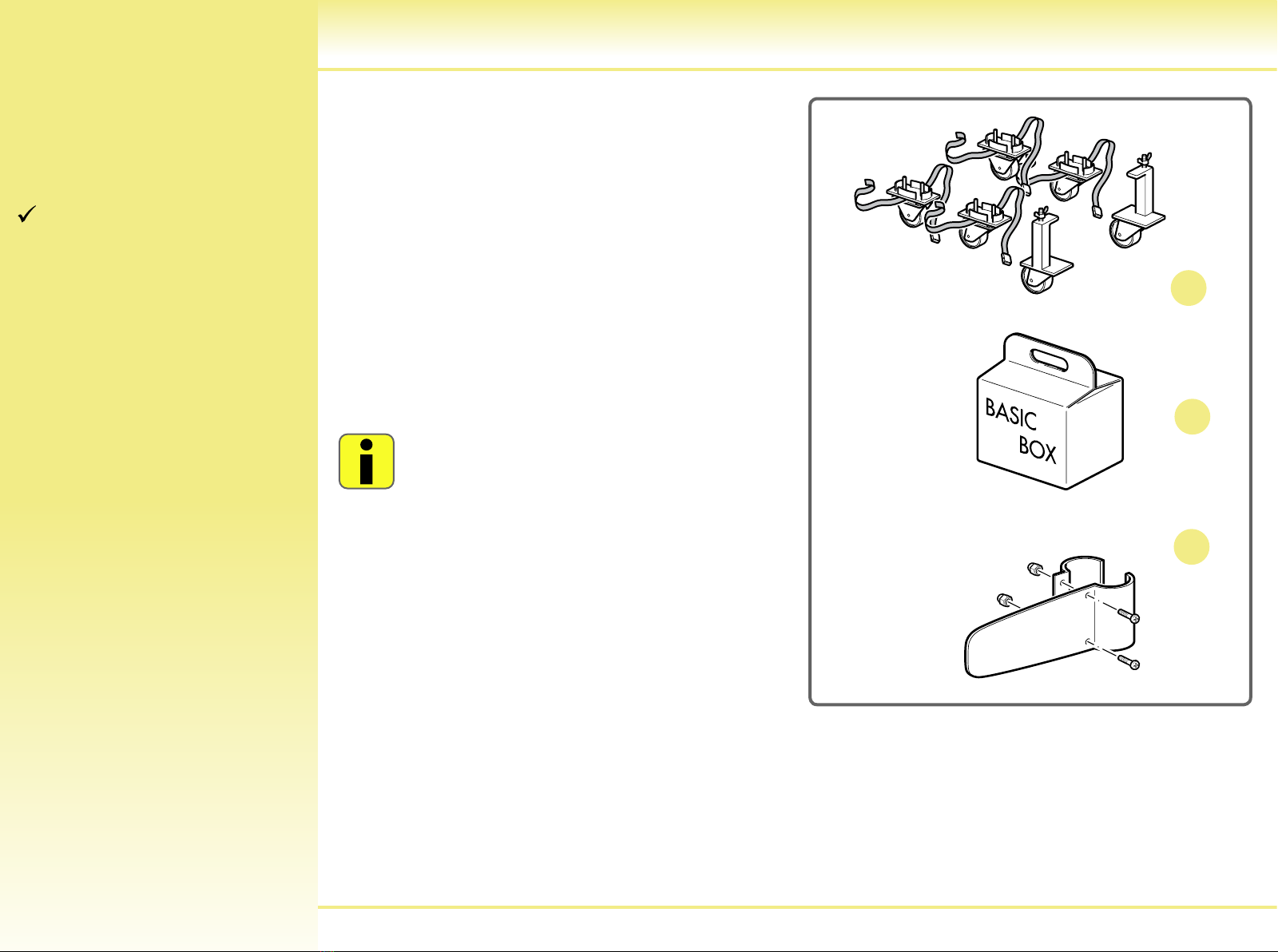
Accessories
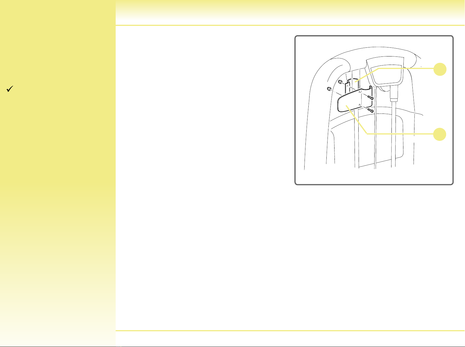
Assembling the number holder
Safety labels and devices
Packing
Place of installation
Unpacking
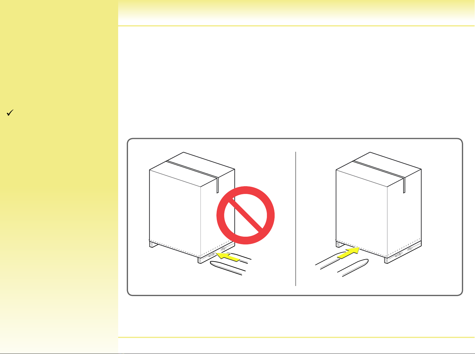
Lifting and handling the
equipment
Adjusting the equipment
Routine maintenance
Replacing the padded
components
Replacing the cable
Adjusting cable tension
Disassembling the front protective
weight stack panel
Technical Service
Codes for original spare parts
Storage
Disposing of the equipment
Using the equipment