Technoton DUT-E 2Bio CAN User manual


Contents
DUT-E 2Bio fuel level sensors. Operation manual. Version 3.1
© Technoton, 2019 2
Contents
Contents ...................................................................................................................... 2
Revision history............................................................................................................. 4
Structure of external links .............................................................................................. 5
Terms and Definitions .................................................................................................... 6
Introduction.................................................................................................................. 8
1 General information and technical specifications of DUT-E 2Bio....................................... 11
1.1 Purpose of use and application area, operation principle .......................................... 11
1.2 Exterior view and delivery set............................................................................... 15
1.3 DUT-E 2Bio design .............................................................................................. 16
1.4 Technical specifications........................................................................................ 17
1.4.1 Main specifications ........................................................................................ 17
1.4.2 Specifications of DUT-E 2Bio CAN output signal................................................. 18
1.4.3 Specifications of DUT-E 2Bio 232/485 output signal........................................... 19
1.4.4 Specifications of DUT-E 2Bio AF output signal ................................................... 21
1.4.5 Specifications of DUT-E 2Bio I output signal ..................................................... 22
1.4.6 Overall dimensions ........................................................................................ 23
2 DUT-E 2Bio installation .............................................................................................. 24
2.1 Exterior inspection prior to works start .................................................................. 24
2.2 Probe cutting according to tank depth.................................................................... 25
2.3 Length extension ................................................................................................ 26
2.4 Screen-filter mounting......................................................................................... 27
2.5 Sensor setup using PC ......................................................................................... 28
2.5.1 Connecting sensor to PC ................................................................................ 28
2.5.2 Interface of Service S6 DUT-E software............................................................ 31
2.5.3 Authorization ................................................................................................ 32
2.5.4 Sensor profile ............................................................................................... 34
2.6 Wireless configuration of sensor using Android devices ............................................ 36
2.6.1 Wireless connection of the sensor to the Android device..................................... 36
2.6.2 Interface of S6 application.............................................................................. 39
2.6.3 Authorization ................................................................................................ 40
2.6.4 Operations with the sensor Profile ................................................................... 41
2.7 Mounting ........................................................................................................... 42
2.8 Electrical connection............................................................................................ 43
2.9 Sensor calibration ............................................................................................... 45
2.10 Fuel tank calibration table .................................................................................. 47
2.11 Adaptation of sensor to specific conditions of operation.......................................... 49

Contents
DUT-E 2Bio fuel level sensors. Operation manual. Version 3.1
© Technoton, 2019 3
2.12 Connection parameters for CAN j1939/S6 interface ............................................... 51
2.13 Connection parameters for
RS-232/RS-485 Modbus,
DUT-E COM (extended LLS)
interface..................................................................... 52
2.14 Voltage, frequency and current output parameters ................................................ 54
2.15 Summation of data............................................................................................ 55
2.16 Automatic recognition of fuel type ....................................................................... 59
3 Sealing .................................................................................................................... 61
4 Measurement accuracy check ..................................................................................... 62
4.1 Basic principles ................................................................................................... 62
4.2 Check tests procedure ......................................................................................... 63
5 Diagnostics and troubleshooting ................................................................................. 64
6 Maintenance............................................................................................................. 65
6.1 General instructions ............................................................................................ 65
6.2 Demounting ....................................................................................................... 66
6.3 Examination ....................................................................................................... 67
6.4 Cleaning ............................................................................................................ 68
7 Packaging ................................................................................................................ 69
8 Storage ................................................................................................................... 70
9 Transportation.......................................................................................................... 71
10 Utilization/re-cycling................................................................................................ 72
Contacts..................................................................................................................... 73
Annex A Template of check test report ........................................................................... 74
Annex B SPN of DUT-E 2Bio Functional modules .............................................................. 75
B.1 Self-diagnostics FM ............................................................................................. 75
B.2 Onboard clock FM ............................................................................................... 77
B.3 Fuel level sensor FM ............................................................................................ 78
B.4 Fuel level control FM ........................................................................................... 80
B.5 Vehicle power supply FM...................................................................................... 82
B.6 Events registrator FM .......................................................................................... 84
Annex C DUT-E 2Bio firmware upgrade .......................................................................... 85
Annex D Electromagnetic compatibility specifications of DUT-E 2Bio................................... 86
Annex E Videography ................................................................................................... 88

Revision history
DUT-E 2Bio fuel level sensors. Operation manual. Version 3.1
© Technoton, 2019 4
Revision history
Version
Date
Editor
Description of changes
1.0
08.2017
OD
Basic version
2.0
12.2017
OD
DUT-E 2Bio connection sequence to Android-device via Bluetooth
using S6 BT Adapter is added.
Sensor configuration procedure from Android-device using
Service S6 DUT-E (Android) is described.
Document’s terms and definitions are updated
(S6 Technology and IoT Burger Technology).
External link structure of the Manual is updated.
Examples of connection schemes of DUT-E 2Bio to telematics units
through S6 cabling system is updated.
3.0
07.2018
OD
New models are added:
- DUT-E 2 Bio 232;
- DUT-E 2 Bio 485;
- DUT-E 2 Bio AF;
- DUT-E 2 Bio I.
Delivery set description is updated.
Electromagnetic compatibility information is added.
Document’s terms and definitions are updated
(CAN j1939/S6 Telematics interface).
3.1
03.2019
OD
Feature of recognition of fuel type in use is added
for DUT-E 2Bio CAN;
Updated list of DUT-E 2Bio CAN data transfer protocol messages;
Register map of DUT-E 2Bio 232/485 output messages according
to Modbus protocol is updated;
SPN list of FM Fuel level sensor is updated.
Structure of external links
DUT-E 2Bio fuel level sensors. Operation manual. Version 3.1
© Technoton, 2019 5
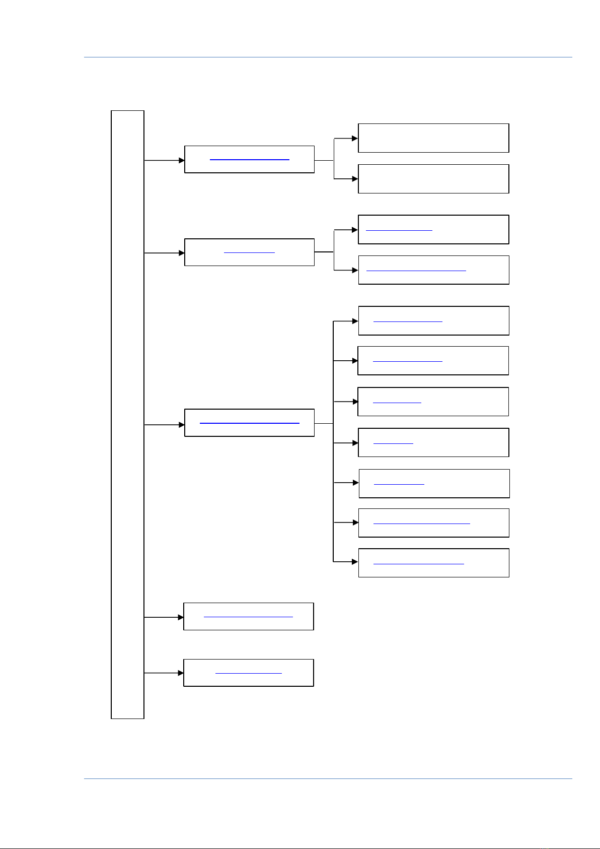
Structure of external links
DUT-E 2Bio fuel level sensors. Operation manual
Document Center
S6 Website
Part S6 Data Base
Part S6 Functional modules
JV Technoton Website
Part Technical support
Part Software/Firmware
YouTube Technoton
ORF 4 Website
Page DUT-E
Page DUT-E GSM
Page DUT-E 2Bio
Page CANUp
Page DFM
DUT-E/DUT-E 2Bio/DUT-E GSM.
Installation manual
CAN j1939/S6 Telematics interface.
Operation manual
This manual suits for next models
4
Other Technoton Accessories manuals


