Technoton DUT-E A5 User manual

FUELLEVELSENSORS
DUT-E 5
DUT-E 10
DUT-E F
DUT-E 232
DUT-E 485
INSTALLATIONMANUAL
Version 5.0

Version 5.0DUT-EInstallationManual
©2007-2011, JV Technoton 2 of 30
Content
Introduction.............................................................................................................. 3
1. Maindataandtechnicalcharacteristics..................................................................... 5
1.1Purposeof use.................................................................................................. 5
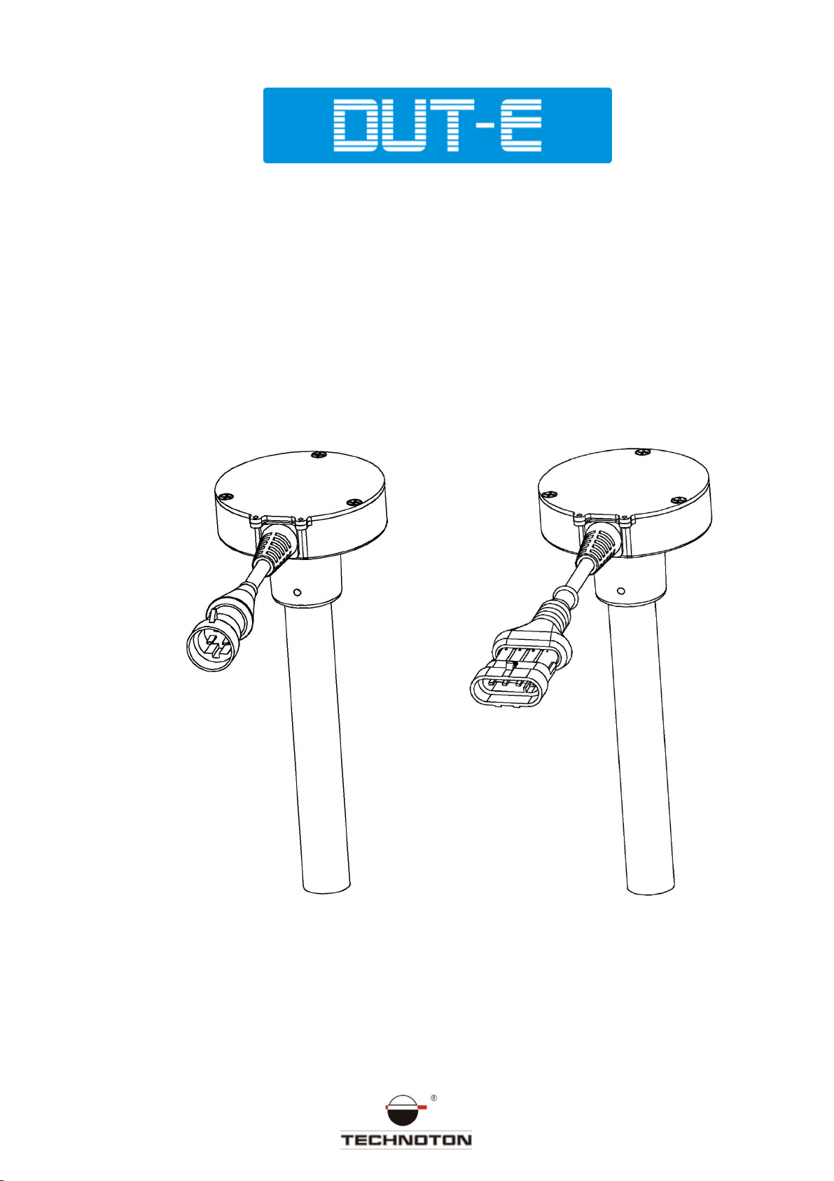
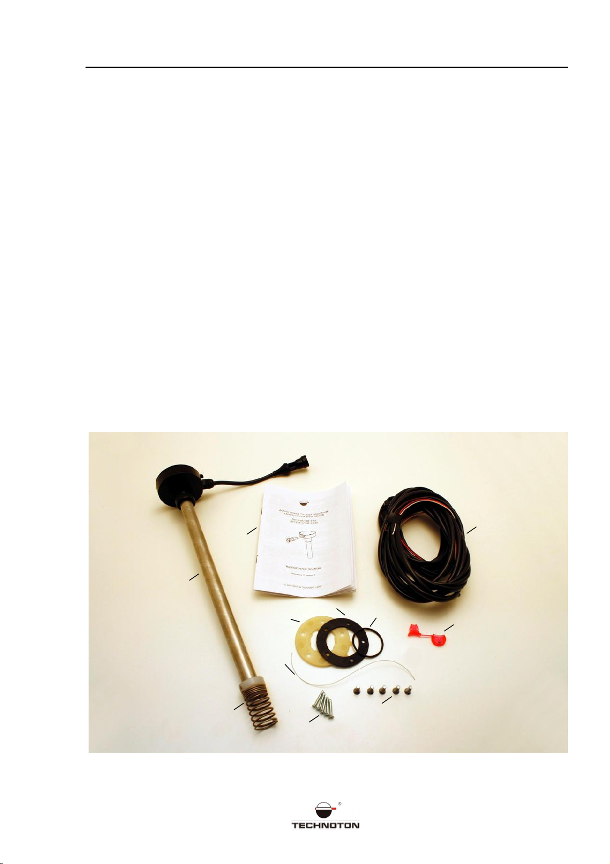
1.2Exterior viewanddeliveryset............................................................................. 5
1.3Technicalcharacteristics .................................................................................... 6
1.3.1Maincharacteristics..................................................................................... 6
1.3.2Characteristics of output signalforDUT-E 5andDUT-E 10 ........................... 6
1.3.3Characteristics of output signalforDUT-EF.................................................... 6
1.3.4Characteristics of output signalforDUT-E232 andDUT-E485.......................... 7
2.Installationandset-up ........................................................................................... 8
2.1Exterior examinationbeforestartingof works....................................................... 8
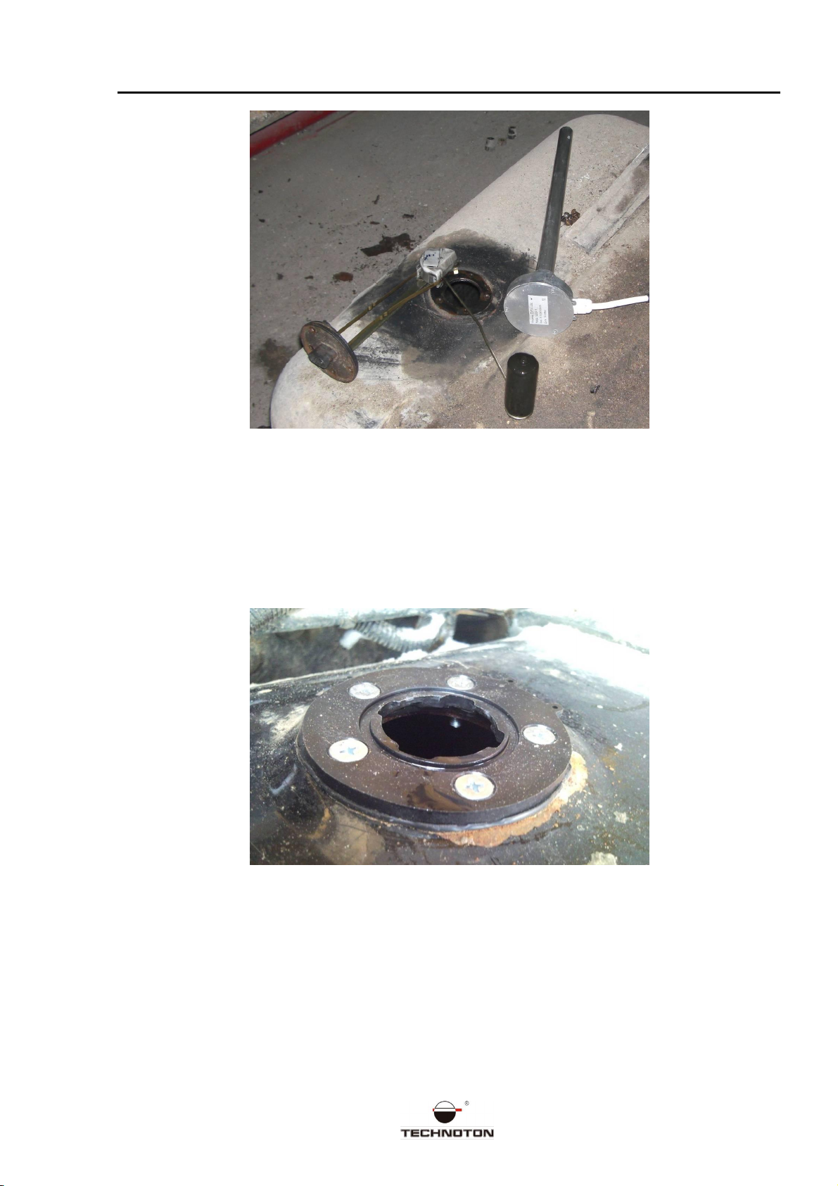
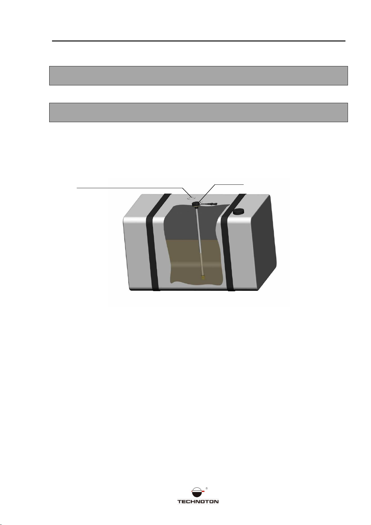
2.2Installationontheplaceof astandardfuelsensor................................................. 8
2.3Installationinto aspecialopening ..................................................................... 10
2.4 Cuttingof themeasuringpartforthenecessarytankdepth ................................. 13
2.5Lengthincreasing............................................................................................ 15
2.6Mounting ....................................................................................................... 15
2.7Electricalconnection........................................................................................ 17
2.8Set-upof theanalogorfrequencyDUT-Esensor ................................................ 19
2.9Set-upof thedigitalDUT-Esensor .................................................................... 19
2.10 Connectionof DUT-Etotheindicator of fuellevel.............................................. 20
2.11 Sealing ........................................................................................................ 21
2.12 Measurement precisioncheck ......................................................................... 22
2.12.1 Basic issues............................................................................................ 22
2.12.2 Controlteststeps.................................................................................... 22
3. Diagnosis and troubleshooting............................................................................... 23
3.1Diagnosis andtroubleshootingof analogDUT-E .................................................. 23
3.2Diagnosis andtroubleshootingof frequencyDUT-E.............................................. 24
3.3Diagnosis andtroubleshootingof digitalDUT-E................................................... 24
Appendix1. Actof thevehicleinspection.................................................................... 26
Appendix2. Tankcalibration..................................................................................... 27
Appendix3. Check-out testprotocol .......................................................................... 29
Appendix4. DUT-Efactorysettings............................................................................ 30

Version 5.0DUT-EInstallationManual
©2007-2011, JV Technoton 3 of 30
Introduction
Recommendationsandregulations given inthe installationmanual are referredto fuel level
sensorsDUT-E (hereinafter DUT-E),developedbyJV Technoton CJSC,Minsk,Belarus. This
document definestheprocedureforinstallationandconnectionof DUT-E,aswell as
providesguidance/recommendations ontheoperation.
DUT-E are used foraccurate measurement ofliquidfuellevelinthevehicle tanksand in
fixed/immovabletanks.
DUT-Ecanbeusedasa standardsensorofthefuel-levelindicator,aswellas apartof the
fuelconsumptioncontrolandvehiclemonitoring systems.
Distinctivefeaturesof DUT-E:
−deliveryset includesallnecessaryitemsforthe properinstallation and
connection, incl. mountingplate, connectingcable, rubbergaskets, screws andseals;
−supply voltage range is from 10 to 50 V;
−possibility toreduce the length upto 30% without calibration*;
−possibility toincrease thelength byusing the additionalsectionsofDUT-E;
−thermo-correction with adjustable coefficient allows tomake automatic updating of
measurements basedontheambient temperature **;
−easy bayonetfastening allows youto installandremovethesensorwithout any tools;
−bottomspringstop serves to give extra stiffness for sensormounting;
−openingsforsealing will help to prevent theunauthorized demounting or operating
troubles of DUT-E;
−self-diagnostic check of DUT-Eallows to controlthe sensor operation.**
*DUT-EA5, DUT-EA10, DUT-EF
** DUT-E 232, DUT-E 485
Themanualisfor the professional users whoarefamiliarwith therules for repairand
installation works onvehicles and whohave professionalknowledgeinthefieldof electrical
andelectronicequipment of various transport vehicles. Toensuretheproper functioningof
theDUT-E, itsinstallationand set-up shouldbecarriedout bycertifiedprofessionalstrained
by the manufacturer.

Version 5.0DUT-EInstallationManual
©2007-2011, JV Technoton 4 of 30
DUT-Ecanbeusedin moderate andcoldclimates.
As for the mechanical stability sensors arevibration-shockproofandvibration-crashworthy.
Marking of sensors is formedasfollows:
Fuellevelsensor DUT-E ХL=Y
To setup DUT-E232 andDUT-E485,Service kitSKDUT-Eis applied. (shouldbepurchased
separately).
Typeofsensor output signal:
5 – analogsignal, voltageupto 4.5V;
10 – analogsignal, voltageupto 9V;
F – frequencysignal, frequency upto
1500Hz;
232 – digitalsignal, interface RS-232;
485 – digitalsignal, interface RS-485.
Nominal length of themeasuring
part (inmm):
- analog: 180, 250, 350, 500,
700, 1000, 1400,2000;
- frequency: 180, 250, 350, 500,
700, 1000, 1400;
- digital: 700, 1000, 1400.
Commercialname

Version 5.0DUT-EInstallationManual
©2007-2011, JV Technoton 5 of 30
1. Maindata andtechnicalcharacteristics
1.1 Purposeof use
FuellevelsensorDUT-Eisdesignedtomeasure thelevelof liquidfuel andother non-
electroconductive liquidsintanks of mobile vehicles and fixed/immovable tanks.
1.2 Exterior viewanddeliveryset
DUT-E deliverysetincludes:
a) sensorDUT-Einset – 1 pce;
b) thebottomstop(forthesensorswith ameasuringpartlengthof 500 mm or more) –
1pce;
c) signalcable7m - 1 pce;
d) mountingplastic plate - 1pce;
e) rubbergasketforthemountingplate - 2pcs;
f) sealingO-ringplate - 2pcs;
g) self-drillingscrew - 5pcs;
h) screwM5x16 - 5 pcs;
i) seal - 2pcs;
j) sealingcord - 2 pcs;
k) specification - 1pce.
Fig.1. Delivery setof DUT-E
а
b
g
h
j
d
e
f i
с
k

Version 5.0DUT-EInstallationManual
©2007-2011, JV Technoton 6 of 30
1.3 Technical characteristics
Power supply of DUT-E is carried out via on-boardvehiclepower system, onwhichitis
installed.
1.3.1 Main characteristics
Table 1. DUT-E maincharacteristics
Therelativemeasurement inaccuracy (tothelength of
themeasuring part),% ±1
Supplyvoltagerange,V
10 - 50
Current
consumption
, mA
≤50 at 12 V
≤25 at 24 V
Protection from pulseinterferences, V
100
Readiness
timeafterpower
-
up,
s
≤10
Temperaturerange, °C
-40 …+85
Protection
levelof housing
IP54
1.3.2 Characteristics of outputsignal for DUT-E 5 and DUT-E 10
Thevoltage valueof the DUT-Eoutput signal hasalineardependence onthemeasuredfuel
level inthetank.
Theoutput signaldoesn’tdependon supplyvoltage.
Table2. Characteristicsof output signalfor DUT-E A5 and DUT-E A10
Voltage, V
Nominallength Aftercutting by 30%
DUT-EA5 Emptytank 1.5 0.65
Fulltank 4.5 2.65
DUT-EA10 Emptytank 2.5 0.65
Fulltank 9.0 5.30
1.3.3 Characteristics of outputsignal for DUT-E F
The frequency valueof the DUT-Eoutput signal hasalineardependence onthemeasured
fuel level inthetank.
Theoutput signaldoesn’tdependon supplyvoltage.
Output cascade – opencollector with loadresistor 10 kOhm.
Table3.Characteristicsofoutput signalfor DUT-EF
Frequency, Hz
Nominallength Aftercutting by 30%
Emptytank 500 270
Fulltank 1500 970

Version 5.0DUT-EInstallationManual
©2007-2011, JV Technoton 7 of 30
1.3.4 Characteristics of outputsignal for DUT-E 232 and DUT-E 485
Characteristicsof output signalof DUT-E232 andDUT-E485 correspond tothespecification
of interfacesof RS-232 andRS-485 accordingly.
Factory interface settings: 19200 bit/s, 8bit, 1stopbit.
Otherfactorysettings aregiveninAppendix4of this manual.
Speedof data exchange via digitalinterfacecanbechosenfrom thefollowing values:4800,
9600, 19200 bit/s.
Theresults of DUT-E measurements canbetransferred via digitalinterface as:
a) standardunits, from0to 1000 (0-emptytank,1000 - fulltank);
b) fuellevelinthetank, mm;
c) fuelvolume, l;
d) fuelvolumeinrelationto thefulltank, %.
Besidesthe remaining fuel amount in the tank,DUT-Epassesinformationabout current
temperature(measuredbythesensorlocatedon the electronic board).
Information transfer is carriedout accordingto DUT-ECOMprotocol.

Version 5.0DUT-EInstallationManual
©2007-2011, JV Technoton 8 of 30
2. Installationand set-up
This chapter provides basic recommendations for the DUT-E installation.
Beforeyou start,youshouldmake external check of thevehicle for any possible failures
andmakeInspectionActof thevehicle (seeAppendix 1)
2.1 Exterior examination before startingof works
Beforeyou start,youshouldmake external check of DUT-Efor any possibledefectsthat
occurredduringtransportation, storageorcarelesshandling:
a) visible damage ofthehousing,measuringpart,mountingplate,rubber gaskets,signal
cableorconnector;
b) tubeplay of themeasuringpart in relation to eachotherand/or to the housing.
By discoveringanydefects, please,contact theproduct supplier.
DUT-Ecanbeinstalled as intotheopeningof the standardfuelsensor* as intoa special
opening inthetank.
*Studycarefullytheschemeof the mountingopeningsforthestandardfuelsensorand
comparewiththeDUT-Einstallationscheme(SeeFigure 9).
ATTENTION! By installingthesensor youshouldfollow safetyrules of the repairworks on
automotive vehicles aswell as safetyrequirements prescribedbytheenterprise.
2.2 Installation on theplaceofa standard fuel sensor
ATTENTION! It is not recommended toinstallthe DUT-E on the place of a standard fuel
sensor because ofitsfarlocation from the geometric center of the tank, and as a result,
inaccuracy in the fuel levelmeasurement may occur. Thereasonforthatissignal
fluctuationof DUT-E thathappens becauseof fuelflowinginsidethetank.
BeforetheDUT- Einstallationit isnecessaryto remove the standard fuelsensorandclean
the installationplace (seeFigure 2)

Version 5.0DUT-EInstallationManual
©2007-2011, JV Technoton 9 of 30
Fig.2. Standardfuelsensorremoval
Aligntheholesof themountingplateandrubber gasketwith theholesinthetank,thenfix
withthe screws thatcometogether with theDUT-E set (seeFigure 3).Screwheadsmustbe
deeplyput into themountingplate.
Fig.3. Mounting plateontheplaceof astandardfuelsensor
Installationof the DUT-E sensor inthemountingplateis given in chapter 2.6of this
manual.

Version 5.0DUT-EInstallationManual
©2007-2011, JV Technoton 10 of 30
2.3 Installation into a specialopening
ATTENTION! Beforedrilling the holesinthetank youshould dismantleit, evaporate oradd
water.
ATTENTION! Beforeyoustartdrillingthehole,please,makesurethatthere are no
partitions insidethetankundertheselectedlocation, whatcanpreventDUT-Einstallation.
Installationsteps:
a) Identify the place where it is supposed to install the sensor. Itisrecommendedtochoose
aplaceinthegeometriccenter ofthetankasit will reducetheerror of fuelvolume
measurement byits vibration duringthemovement;
Fig.4. Recommendedplacefor DUT-E installation
DUT
-
E
Regular/stand
ardfuellevelsensor

Version 5.0DUT-EInstallationManual
©2007-2011, JV Technoton 11 of 30
b) Marktheplaceanddrilltheholes accordingto thefollowingscheme(SeeFigure 5);
BEATTENTIVE! Mounting plate can be installed only in one position onthepre-drilled
holes! Prior to markingand drilling, please, study theplacewhereitis supposed toinstall
theplate so that holes for sealingwere locatedinanaccessibleposition.
Fig.5. Schemeof theholesforthemounting plate
Drillingis recommended to do with thecutter Ø38mm (seeFigure 6)
Fig.6. Cutter
Toprevent metalshavings in thetank it isrecommendedtoapplyalotofgrease, for
example, solid oil,on placeofthehole drilling.
c) Put thegasketandmountingplateonthepreparedhole,fixwith screwsorself-drilling
screws thatcomeinthedeliveryset.
ATTENTION! Forthe further sealingof thesensor it is recommended toput a sealing cord
throughtheholes forsealingof themountingplate prior toits installationonthefueltank!
5 HolesV5
-
6H

Version 5.0DUT-EInstallationManual
©2007-2011, JV Technoton 12 of 30
Fig.7. Installation scheme of the mounting plate
ATTENTION! While attachingtheplatetothetank,makesure, thatthescrewheads or
self-drilling screw headsare notwarped and deeplyput intothemountingplate so that to
provideelectricalinsulation of the vehicletankcasingfrom theDUT-E!
Asealing cord
Screw M5x16orself
-
drilling screw
Mounting plate
Rubbergasket
Fueltank

Version 5.0DUT-EInstallationManual
©2007-2011, JV Technoton 13 of 30
2.4 Cutting of the measuringpart forthenecessarytank
depth
Inordertoavoid the shortcircuitof themeasuringpart tubes causedby wateror
electroconductive residues that are gathered on thebottomof thetank,thereshouldbeat
least 2cmgapbetween thetube endof the DUT-E measuringpart andthebottomof the
fueltank.
ATTENTION!
For DUT-E A5, DUT-E A10, DUT-E F: allowed to make cutting upto 30% without further
calibration;
For DUT-E 232, DUT-E 485: allowed to make cutting up to 70% withfurthercalibration.
ATTENTION! DUT-E cutting shouldbe done bymeansof hacksaw or with a pipecutter of a
suitablediameter.Cuttingedges shouldbethoroughlycleaned upandwashedupwith the
fuel.
Steps by DUT-E cutting:
a) measurethedepth fromthemountingplatetillthetankbottom (seeFig. 8);
Fig.8. Measuring thedepth of thefueltank

Version 5.0DUT-EInstallationManual
©2007-2011, JV Technoton 14 of 30
b) cut theDUT-Emeasuringpartbasedonthelocationof thetubeendatadistanceof
2-3cmfromthetankbottom (seeFig. 9)
Fig.9. Cutting themeasuring partof DUT-E
c) cleantheedges fromburrsandshavings toremoveall elementsthatcan cause
electricalinterlocking of the tubes ofthe measuringpartbetween eachother (see
Fig. 10)
Fig.10. View of the cutting placeafter cleaning
d) in caseof DUT-E232 orDUT-E485 cuttingyou shouldcalibratethesensorusingthe
ServicekitSKDUT-E(Seeitem2.9).

Version 5.0DUT-EInstallationManual
©2007-2011, JV Technoton 15 of 30
2.5 Length increasing
Length increasing is carriedout by attaching of DUT-E additional sectiontothe measuring
part.
Model range of DUT-Eadditionalsectionsinclude:KDC 250,KDC500 and KDC 1000 with
lengths of 250, 500 and1000 mm correspondingly.
Fig.11. Additionalsection of DUT-E
Lengthincreasingof analogandfrequencyDUT-E sensors ispossible only for restoring the
length after cuttingand only within limits of theDUT-Enominallength.
Lengthincreasingfor digitalDUT-E sensor is allowed to alengthof 6000mm.
Thedetailedinformationforthemountingprocessiscontainedinthe operationmanual for
DUT-Eadditionalsection.
Extra sectionsof DUT-Ecanbecut to thedesired length.When cuttingyoushould follow
therecommendations given in item 2.4of this guide.
2.6 Mounting
Toprovide extrastiffness tothesensor youneedtoinstall bottom spring stop (which isa
partofdeliveryset) ontheendof themeasuringpart of the DUT-E. Just put the bottom
springstop onthetube andfix toit bytighteningthescrewsattheendofthe bottom
spring stop.
Inorderto fix theDUT-E it isnecessaryto put an O-ringright on thedapof the mounting
plate,andthen put the sensor intothehole (see Fig.12), press it withforceandlockby
turningclockwise till sealingholesof theDUT-Ehousing andmountingplatecometogether
(seeFig. 13).
ATTENTION! During installationit isrecommendedtoapplyasmallamount of oilor fuel
ontheO-ring of the mountingplate so that toprevent itsdeformation whenyou fix the
DUT-Einside themountingplate.

Version 5.0DUT-EInstallationManual
©2007-2011, JV Technoton 16 of 30
Fig.12. Installationof DUT-E
Fig.13. Installation scheme of DUT-E
Installationshouldbedonein such awaythataftertheDUT-E mountingthe sealing openings
onthe mounting plateandDUT-E housing were locatedunder eachother.
SealingO-ring
Fueltank
DUT
-
E

Version 5.0DUT-EInstallationManual
©2007-2011, JV Technoton 17 of 30
2.7 Electrical connection
Theelectricalconnectionof analogand frequency DUT-E iscarriedout in accordancewith
thefollowing pinassignment (Figure 14, Table4):
Fig.14. Pins of analogandfrequency DUT-E sensors
Table4. Pin assignment of analogandfrequency DUT-E
PinNo Circuitname Cablecolour Remark
1. Т701/Т034 white Analogorfrequency
output
2. GND/Т734 brown "Ground" of the
vehicle
3. VBATT orange Powervoltage
Theelectricalconnectionof digital DUT-E is carriedout inaccordancewith thefollowing pin
assignment (Figure 15,Table 5).
Fig.15. Pins of digital DUT-E

Version 5.0DUT-EInstallationManual
©2007-2011, JV Technoton 18 of 30
Table5. Pin assignment of digital DUT-E
PinNo Circuitname Cablecolour Remark
1.
VBAT orange Powervoltage
2.
GND brown "Ground" of thevehicle
3.
232R/485A white
Receiveddata (RS 232)
Dataexchange (RS 485)
4. 232T/485B red
Transferreddata (RS 232)
Dataexchange (RS 485)
ATTENTION! Study thoroughly the textual wire tagging! Themanufacturerkeeps theright
to changethecolors ofthewires.
The DUT-E housingiselectricallyconnectedwiththe "minus" of DUT-E(brownwire
harness).
The mountingplatemadeof dielectric plastic material provides electricalinsulationof the
DUT-Ecasingfromthe vehiclecasing (of thetank).
ATTENTION! Signalcableis stronglyrecommended tostack togetherwith thestandard
wiring ofthevehicleand mandatory to fixitsposition bymeans of tie-laps every0.5 m.
(see Fig. 16).
Fig.16. DUT-E cablelaying
During the set-upof therecordinganddisplay devicesitisnecessarytomakeasetting
"DUT-E readings do notdependonthevoltage of on-board power system" (if suchsetting
available).
ATTENTION! Connectionof theDUT-Etotheon-boardpowersystemand"ground"is
carriedout inthesameplaces wheretherecordinganddisplay devicesareconnected.
Afterinstallationandconnectionof DUT-E you should calibratethe tank(See Appendix 2).

Version 5.0DUT-EInstallationManual
©2007-2011, JV Technoton 19 of 30
2.8 Set-up of the analogor frequency DUT-E sensor
Setup andcalibrationof analogandfrequencyDUT-Eis notrequired.
2.9 Set-up of the digital DUT-E sensor
ATTENTION! Setupof thedigitalDUT-Ecan bepossible onlybemeansof theprogram
"ServiceDUT-E" and servicekitSKDUT-E(shouldbepurchased separately).
Detailed descriptionof configurationoptionsDUT-Edescribedintheoperating manualfor
servicekitSKDUT-E.
AllDUT-E are deliveredcalibrated.
Thecalibration willbe broken after the lengthcuttingorincreasingof digitalDUT-E sensors.
Calibration of the sensor is possibleonlywiththehelpof Servicekit SK DUT-E. Detailed
informationabout calibrationprocess is givenintheoperationmanualfor SK DUT-E.
By meansof the "ServiceDUT-E" software you canalso setthedesiredDUT-E modes:
- Filtrationtime(default setting 10s);
- Interval ofperiodic dataoutput (default setting 1s);
- Data output mode (default setting HEX)(SeeFigure 17).
Filtrationtime is thetimeinterval that precede thedatatransmission and whichis used to
calculate the averagefuellevelinthetank. Thus, thevalueof thefuellevelinthetank
whichis transmitted by the sensor to therecording anddisplay device isnottheinstant
value, but the averaged value over theset periodoftime whichhasprecededthemoment
of thedatatransfer.
Fig.17. WindowoftheprogramService DUT-E
For the DUT-E485 thesettingof theuniqueaddress foreach sensor inthenetworkRS 485
is also available(See Figure 17).

Version 5.0DUT-EInstallationManual
©2007-2011, JV Technoton 20 of 30
2.10 Connection of DUT-E to theindicator of fuel level
By installingtheDUT-E onthe placeof standard fuellevelsensor you may needto restore
the indicator of remainingfuelinthetank toworkingcondition. Inorder toimplement this
function you needto use an interfacedevice UC.
ATTENTION! Interfacedevicecomplies onlywith DUT-E A5!
Table 6. Interfacedevicemodels
ArticleorderNo Remark
UС-1-90 Emulation of the level sensor with low resistance:0-90 Ohm
UС-1-800 Emulation of the level sensor with high resistance: 800-185
Ohm
Fig.18. Exteriorviewof theinterfacedeviceU -1
Table7. Circuit nameandwirecolours:
PinNo Circuitname Wirecolour* Remark
1 T034 white Signal from the fuel
levelsensor (input)
2 GND brown Vehicleground
3 T734 pink Fuellevelindicator
(output)
4 T733 pink Controllamp of the
fuellevel (output)
5 VBAT orange Powervoltage
* Themanufacturerreserves theright to changethewire colours.
This manual suits for next models
4
Table of contents
Other Technoton Accessories manuals
Popular Accessories manuals by other brands

Louroe Electronics
Louroe Electronics AP-8 Installation and operating instructions

Texecom
Texecom Medusa Installation instructions manual

Leuze electronic
Leuze electronic MSI 400 Series operating instructions

Dometic
Dometic A&E Systems 8500 user guide

Masimo
Masimo RD SET E1 Directions for use

Panasonic
Panasonic EX-L200 Series instruction manual