Technoware ECO 1.3 User manual

Uninterruptible Power Supply
ECO 0.50
ECO 0.70
ECO 0.90
ECO 1.1
ECO 1.3
User’s manual


UPS ECO 0.50 – 0.70 – 0.90 – 1.1 - 1.3 1 User’s manual
In ex
Safety Warnings ................................................................................ 2
1
Intro uction ................................................................................. 3
2
General Characteristics ................................................................... 3
3
Receipt an site selection ................................................................ 4
4
EXTERNAL DESCRIPTION .................................................................. 5
4.1
Front Panel ............................................................................. 5
4.2
Rear S de ................................................................................ 6
5
Electrical Installation an First Start Up ............................................... 6
6
Functioning ................................................................................. 7
6.1
Normal Mode ........................................................................... 7
6.2
Battery Mode ........................................................................... 8
6.3
Low Battery and Automat c Restart ................................................. 8
6.4
Load Control ............................................................................ 8
6.5
Fault Cond t on ........................................................................ 8
7
Technical Characteristics ................................................................. 9
8
Maintenance ............................................................................... 10
8.1
UPS Clean ng ......................................................................... 10
8.2
Battery ................................................................................ 10
8.3
Battery Replacement ............................................................... 10
8.4
Operator Safety ...................................................................... 11
9
Troubleshooting ........................................................................... 12
Conformity to the European Directives ................................................... 13
Pro uct Disposal ............................................................................... 13
Lea Batteries ................................................................................. 13
© Copyr ght 2011 TECNOWARE s.r.l. All r ghts reserved.
All trademarks are property of the r respect ve owners.
TECNOWARE s.r.l.
V a Montetr n , 2E – Mol no del P ano – Florence – Italy
www.tecnoware.com
Ed t on: February 2011 – vers on: 1.0
No part of th s manual may be reproduced, even part ally, w thout the
author sat on of TECNOWARE s.r.l.
TECNOWARE s.r.l. reserves the r ght to change spec f cat ons at any t me
and w thout not ce.

User’s manual 2 UPS ECO 0.50 – 0.70 – 0.90 – 1.1 – 1.3
Safety Warnings
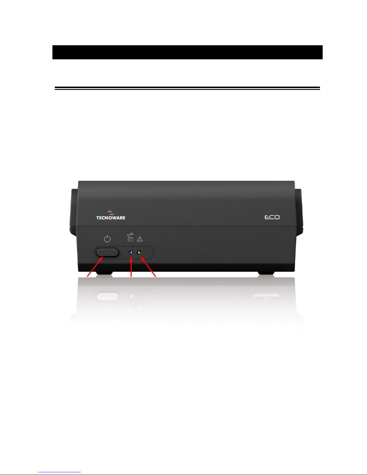
Rea this manual carefully an completely before installing an using the TECNOWARE ECO
Uninterruptible Power Supply, which, from here after, will also be referre to as UPS.
This manual shoul be kept close to the UPS an rea before the UPS is installe an use .
The UPS must be use only by properly traine personnel. To ensure correct an safe
operations, it is necessary that operators an maintenance personnel observe the general
safety Stan ar s as well as the specific instructions inclu e in this manual.
Risk of electric shock: o not remove the cover. The UPS contains internal parts, which are at a
high Voltage an are potentially angerous, capable of causing injury or eath by electric
shock.
There are no internal parts in the UPS, which are user serviceable. Any repair or maintenance
work must be performe exclusively by qualifie technical personnel authorize by
TECNOWARE. TECNOWARE eclines any responsibility if this warning is isregar e .
Warning to the technical personnel authorize for Service: since internal components are
connecte to the batteries, they will remain powere , an therefore angerous, even after the
UPS has been isconnecte from AC power mains. Before any repair or maintenance work,
isconnect the batteries, by removing the positive cable (re colour) from the positive pole of
the battery.
It is compulsory to groun the UPS accor ing to Safety Stan ar s. The AC mains power supply
socket use to power the UPS must have an earth connection.
In the event of AC main power supply failure (when the UPS works in Battery mo e), o not
unplug the power supply cable to the UPS to ensure earth continuity to the connecte loa s.
Since the AC mains power supply cable acts as a separation evice, the AC mains power socket
use to supply the UPS an /or the rear si e of the UPS must be accessible to easily isconnect
the cable in case of angerous con itions.
Risk of electric shock at the Output lines when the UPS is ON.
Risk of electric shock at the Output lines while the unit is connecte to the AC utility line.
Do not obstruct ventilation slots or holes an o not rest any object on top of the UPS.
Do not insert objects or pour liqui s in the ventilation holes.
Install the UPS in oors, in a protecte , clean an moisture-free environment.
Do not expose to the irect sun light.
Do not keep liqui s, flammable gases or corrosive substances near the UPS.

UPS ECO 0.50 – 0.70 – 0.90 – 1.1 - 1.3 3 User’s manual
1Intro uction
ECO s an UPS (Un nterrupt ble Power Supply) spec f cally des gned to protect your computer from any type of
rregular t es n the AC l ne (such as black-outs, under or over voltages, m cro- nterrupt ons), wh ch often cause
damage to your Hardware and Software.
Under normal AC l ne cond t on, ECO f lters frequently occurr ng electr cal d sturbances (such as trans ents, sp kes,
nterferences, etc.), thus protect ng all dev ces connected to the outlets, and recharg ng the batter es n an deal
way. In case of anomaly to the AC l ne, the UPS cont nues feed ng the protected equ pment.
Rea this manual carefully before using the ECO; it inclu es important safety warnings
an useful a vices for correct use an installation.
This manual is a gui e that enables you to correctly install an use your UPS. This
manual inclu es important SAFETY instructions for the operator, for the UPS correct
installation, an gives useful a vice on the pro uct an battery maintenance. For any
type of problem, please refer to this manual before calling the customer service.
ECO s constantly be ng developed and mproved: consequently, your un t may d ffer somewhat from the
descr pt on conta ned n th s manual.
Th s manual ncludes the follow ng models:
•ECO 0.50 (500 VA)
•ECO 0.70 (700 VA)
•ECO 0.90 (900 VA)
•ECO 1.1 (1100 VA)
•ECO 1.3 (1300 VA)
In th s manual ECO w ll s mply be referred to as UPS.
2General Characteristics
ECO has all the advanced features, wh ch guarantee max mum rel ab l ty and safety:
•All funct ons are controlled by a m croprocessor, g v ng full guarantee of h gh rel ab l ty.
•Overload protect on both n normal mode and n battery mode.
•H gh performance battery charger, wh ch extends the battery med um l fe ensur ng an opt mal recharge.
•Start up even f the electr cal network s not ava lable.
•Automat c restart after an automat c shut down due to a low battery cond t on once the AC ut l ty power
returns.
•Adapts automat cally to 50 or 60 Hz nput frequency.

User’s manual 4 UPS ECO 0.50 – 0.70 – 0.90 – 1.1 – 1.3
•V sual and acoust c s gnals nd cat ng operat ng mode and alarm/fault cond t ons.
•H gh eff c ency
•Max mum rel ab l ty
•Smart des gn and easy to use
3Receipt an site selection
Carefully remove the UPS from ts packag ng, and carry out a met culous nspect on. We recommend keep ng the
or g nal packag ng n a secure place, n case you need to send the UPS for ma ntenance purposes. In case of
transport damage, not fy the carr er and dealer mmed ately.
We recommend pay ng attent on to the below po nts n order to choose a correct placement for your UPS:
•The UPS s des gned to operate n a protected env ronment (e.g. off ces). We therefore recommend
nstall ng t n a place w th very l ttle or no hum d ty, dust or smoke.
•In all c rcumstances, see the “Techn cal Character st cs” chapter for env ronmental spec f cat ons and
check that the selected area meets these spec f cat ons.
•Dur ng normal operat on the UPS d scharges a m n mal amount of heat. So t s necessary to leave at least
20 cm of unobstructed space all around the UPS n order to keep t properly vent lated.
•Do not obstruct vent lat on holes.
•Do not nsert objects or pour l qu ds n the vent lat on holes.
•Do not rest any object on top of the UPS.
•Do not keep l qu ds, flammable gases or corros ve substances near the un t.
•Install the UPS on a properly t led floor. Avo d the nstallat on on a floor that s not t led flat.

UPS ECO 0.50 – 0.70 – 0.90 – 1.1 - 1.3 5 User’s manual
4EXTERNAL DESCRIPTION
4.1 Front Panel
The front panel nforms the user about operat ng status, alarm cond t ons through 2 leds.
On the front panel there are (see f gure 1):
1. The ON/OFF button: enables the user to turn ON/OFF the UPS.
2. The LINE/BATTERY led: th s led (blue color) s always on dur ng the funct on ng n Normal Mode, t flashes
one t me every 4 seconds n Battery mode and t flashes one t me every second n Low Battery cond t on.
3. The ALARM led: th s led (red color) s on to nd cate Alarm/Fault cond t on.
Figure 1 – Front panel
1
2
3

User’s manual 6 UPS ECO 0.50 – 0.70 – 0.90 – 1.1 – 1.3
4.2 Rear Si e
Figure 2 – Rear Si e
On ECO rear s de there are (see f gure 2):
1. Groun e AC Input power socket: IEC C14 type; to connect the UPS to the AC ut l ty l ne.
2. Input fuse: electr cal spec f cat on: max current 5 A, voltage 250 V.
3. Groun e UPS Output receptacles: IEC C13 type.
5Electrical Installation an First Start Up
We adv se you to follow the steps below expla ned for greater safety:
1. Sw tch off all the dev ces (Personal Computer or other electron c dev ces) that need to be suppl ed by the
UPS.
2. Connect the UPS Input socket to the AC l ne outlet through the Personal Computer supply ng cable. It is
man atory to groun the AC line outlet accor ing to the Safety Stan ar s. Carefully check the ground ng,
make sure that the ut l ty power s ava lable, and that ts range falls w th n the UPS spec f cat ons (refer to
the “Techn cal Character st cs” chapter).
3. Press the ON/OFF button on the front panel for about 2 seconds unt l the UPS em ts a br ef acoust c s gnal.
The UPS turns on the leds the front panel and performs a functioning SELF-TEST. After some seconds the
UPS starts to work n Normal mo e: the LINE/BATTERY led s on. Leave the UPS n Normal mode for at least
4 hours n order to completely recharge the batter es
1
2
3

UPS ECO 0.50 – 0.70 – 0.90 – 1.1 - 1.3 7 User’s manual
4. Sw tch the UPS off (by press ng aga n the ON/OFF button for about 2 seconds).
5. Connect the dev ces to be suppl ed to the UPS outputs, by us ng only the ncluded cables. Be sure all the
dev ces have the ma n sw tch n ON pos t on.
6. Turn on the UPS aga n. Check that t starts work ng correctly and t doesn’t s gnal any sort of anomaly.
Moreover be sure that all the dev ces connected to the UPS outputs are work ng correctly.
7. S mulate a black-out by remov ng the AC Input l ne. The UPS starts work ng n Battery mo e: the UPS em ts
an acoust c alarm s gnal every 4 seconds and s multaneously the LINE/BATTERY led flashes.
8. Be sure that all the dev ces connected to the UPS outputs are work ng correctly and the UPS doesn’t s gnal
any sort of anomaly.
9. Restore the AC Input l ne: after few seconds the UPS turns back n Normal mode.
Before us ng ECO normally, leave t n Normal mode n order to charge the batter es completely as spec f ed at
po nt 3. The batter es reach the 90% of the r capac ty after about 4 hours of recharge.
It is compulsory to groun /earth the UPS accor ing to the Safety Stan ar s.
Risk of electric shock at the Output lines if the UPS is ON, even when the UPS is not
connecte to AC utility line.
Risk of electric shock at the Output lines while the unit is connecte to the AC utility
line.
Risk of electric shock: o not remove the cover. The UPS contains internal parts, which
are at a high Voltage an are potentially angerous, capable of causing injury or eath
by electric shock.
There are no internal parts in the UPS that are user serviceable. Any repair or
maintenance work must be performe exclusively by qualifie technical personnel
authorize by TECNOWARE. TECNOWARE eclines any responsibility if this warning is
isregar e .
Disregar for these warnings may lea to a risk of electric shock to operators.
6Functioning
6.1 Normal Mo e
The UPS typ cally works n Normal mo e: Input ma ns power s ava lable and ts ampl tude s w th n spec f cat ons.
In Normal mode the LINE/BATTERY led s always on.
Dur ng Normal mode, the UPS recharges the batter es and keeps them n an opt mal charg ng voltage.

User’s manual 8 UPS ECO 0.50 – 0.70 – 0.90 – 1.1 – 1.3
6.2 Battery Mo e
The UPS automat cally runs n Battery mo e f the AC Input L ne voltage ampl tude gets out of secur ty l m ts ( n
case of a black-out or over-voltage/low-voltage): n th s case, the UPS suppl es the requ red output power by ts
nternal battery and by the Inverter block.
The UPS automat cally returns n Normal mode a few seconds after the AC Input L ne s recovered.
In Battery mode the UPS em ts an acoust c alarm s gnal every 4 seconds and s multaneously the LINE/BATTERY led
flashes.
6.3 Low Battery an Automatic Restart
In Battery mode, ECO nd cates the Low Battery cond t on whenever the battery reaches a charge level allow ng
connected dev ces to operate for approx mately one more m nute.
Dur ng Low Battery cond t on the UPS em ts an acoust c alarm s gnal every second and s multaneously the
LINE/BATTERY led flashes.
If AC Input does not come back on w th n few m nutes, the UPS shuts- own automatically thus prevent ng the
batter es from d scharg ng excess vely; the UPS stops supply ng Output power, deact vates control panel nd cat on
and goes to a wa t ng state. Once AC Input comes back on, the UPS restarts automatically and after some seconds
t goes back to work n Normal mode.
After a complete d scharge, the UPS needs 4 hours to recharge completely the batter es. The UPS recharges
batter es automat cally f t works n Normal mode.
6.4 Loa Control
Dur ng the funct on ng n Battery Mode, f the Output load s h gher than nom nal value (Overloa con ition), the
UPS may automat cally sw tch off, protect ng tself from th s anomalous s tuat on. In th s case, the user must
reduce power w th n the spec f cat ons by d sconnect ng the dev ces that cause the Overloa con ition.
Do not connect a loa greater than rate value to the UPS (see POWER specifications in
the chapter “Technical Characteristics”), as this may amage the unit. In this case the
warranty is voi .
6.5 Fault Con ition
The UPS nd cates the Fault con ition by l ght ng of the Alarm led and by em tt ng a cont nuous acoust c alarm.
Dur ng Fault cond t on, the UPS doesn’t supply Output power and so all the suppl ed dev ces are sw tched off.

UPS ECO 0.50 – 0.70 – 0.90 – 1.1 - 1.3 9 User’s manual
7Technical Characteristics
UPS ECO Mo el
0.50
0.70
0.90
1.1 1.3
Power 500 VA
(300 W)
700 VA
(420 W)
900 VA
(540 W)
1100 VA
(660 W)
1300 VA
(780 W)
Recommended for:
Personal
Computer w th
350W PSU
(250W real
power)
+ LCD Mon tor
(40W)
Personal
Computer w th
450W PSU
(350W real
power)
+ LCD Mon tor
(40W)
Personal
Computer w th
550W PSU
(450W real
power)
+ LCD Mon tor
(60W)
Personal
Computer w th
600W PSU
(500W real
power)
+ LCD Mon tor
(60W)
Personal
Computer w th
650W PSU
(550W real
power)
+ LCD Mon tor
(100W)
Technology Easy Interact ve
Nom nal Input Voltage S ngle-phase 230 Vac
Input Voltage Range +15% -23%
Input/Output Frequency 50/60 Hz (automat c select on)
Input Frequency Range +/- 5%
Nom nal Output Voltage S ngle-phase 230 Vac
Output Voltage Regulat on
(Normal mode) As Input
Output Voltage Regulat on
(Battery mode) +/- 5%
Output Inverter Waveform Mod f ed S newave
Accepted Overload < 130%
Cert f cat ons
CE
Standards: CEI EN 62040-1: 2009 (Low Voltage D rect ve) –
CEI EN 62040-2: 2006 (EMC D rect ve)
Eff c ency 92%
Battery Type Lead ac d, sealed, free ma ntenance
Number of batter es 1
Nom nal Battery Voltage 12 Vdc
Battery Spec f cat ons 12 Vdc – 4,5 Ah
– 6 cells
12 Vdc – 5 A
– 6 cells
12 Vdc – 7,2 Ah
– 6 cells
12 Vdc – 7,2 Ah
– 6 cells
12 Vdc – 9 Ah
– 6 cells
Backup T me (typ cal) 10 m n
Battery Charge T me (typ cal) 4 hours
Aud ble No se (at 1 meter) < 40 dBA
Cool ng Natural
Env ronmental Operat ve Spec f cat on Temperature: 0-40 °C - Hum d ty 0-95% (w thout condensat on)
Alt tude: max 3.000 mt
Output sockets 2 Output sockets (IEC type)
D mens on (W x H x D) 20,7 x 8,3 x 22,8 cm
Net We ght 2,5 Kg 2.6 Kg 3,5 Kg 3.6 Kg 4Kg
Techn cal data may change w thout pr or not ce

User’s manual 10 UPS ECO 0.50 – 0.70 – 0.90 – 1.1 – 1.3
8Maintenance
8.1 UPS Cleaning
Before starting any cleaning operation, be sure that:
1. The AC Input Voltage for the UPS has been remove .
2. The UPS is OFF.
Use only a cloth dampened w th water to clean the un t.
If UPS works n an env ronmental unusually dusty or d rty, remove the d rty from the vent lat on holes.
Before restart ng the UPS be sure t s completely dry. If any l qu d gets ns de the UPS, do not start the un t and
contact Techn cal Serv ce mmed ately.
8.2 Battery
If the UPS s NOT go ng to be used for a long per od of t me, ensure that the batter es are left fully charged.
If the UPS has not been used for more than three months, go through the “F rst Start Up” procedure descr bed n
the chapter 5 before us ng t aga n.
Please keep n m nd that the batter es must be recharged at least once a month. Take n m nd that batter es are
recharged automat cally f the UPS works n Normal mode or f the UPS s off and connected to the AC Input L ne.
Battery l fe strongly depends on the amb ent temperature. There are also other factors l ke the number of charge-
d scharge cycles, the d scharge depth, hum d ty and alt tude.
The recommended env ronmental spec f cat ons for a correct use of batter es are l sted n the “Techn cal
Spec f cat ons” sect on.
8.3 Battery Replacement
Battery replacement must be performed exclus vely by qual f ed and author zed techn cal personnel. We adv se
you to follow the steps below expla ned for greater safety:
1. Turn the UPS off and d sconnect the AC Input L ne for the UPS.
2. Unscrew the 4 screws on the UPS bottom s de. Remove the case cover and so you can access to the battery
locat on.
3. D sconnect the battery w res and gently extract the battery from the case.
4. The new battery must be exactly the same type as the or g nal one.
5. Put ns de the new battery and connect t as the or g nal one.
6. Reassemble the case cover.

UPS ECO 0.50 – 0.70 – 0.90 – 1.1 - 1.3 11 User’s manual
Battery replacement must be performe exclusively by qualifie technical personnel
authorize by TECNOWARE. TECNOWARE eclines any responsibility if this warning is
isregar e .
When replacing batteries, replace with the same type an number.
CAUTION: A battery can present a risk of electrical shock an high short circuit current.
The following precautions shoul be observe when working on batteries:
a) Remove watches, rings or other metal objects;
b) Use tools with insulate han les;
c) Wear rubber gloves an boots;
) Do not lay tools or metal parts on top of batteries;
e) Disconnect the charging source prior to connecting or isconnecting battery
terminals;
f) Determine if battery is ina vertently groun e . If ina vertently groun e , remove
source from groun .
CAUTION: Do not ispose of batteries in a fire. The batteries may explo e.
CAUTION: Do not open or mutilate batteries. Release electrolyte is harmful to the skin
an eyes. It may be toxic.
8.4 Operator Safety
Whenever the UPS s not respond ng anymore to or g nal character st cs, the UPS must be made non-operat ve and
every usage not author sed must be avo ded. After t w ll be necessary to refer to qual f ed techn cal personnel.
Or g nal safety character st cs m ght not be f, for example, the UPS has v s ble damage or rregular operat on.

User’s manual 12 UPS ECO 0.50 – 0.70 – 0.90 – 1.1 – 1.3
9Troubleshooting
Alarms and problems you may encounter dur ng operat ng the UPS are g ven n the table below.
Apply
the suggest ons correspond ng to each anomaly as descr bed nto the table.
If your anomaly s excluded or the suggested act ons do not solve your problem, consult the Techn cal Serv ce.
Please g ve the follow ng nformat on to the Techn cal Serv ce:
Model and ser al number of the UPS, wh ch can be found on the nameplate on the rear of the UPS.
Descr pt on of anomaly.
Risk of electric shock: o not remove the cover. The UPS contains internal parts that are
at a high Voltage an are potentially angerous, capable of causing injury or eath by
electric shock.
There are no internal parts in the UPS that are user serviceable. Any repair or
maintenance work must be performe exclusively by qualifie technical personnel
authorize by TECNOWARE.
TECNOWARE eclines any responsibility if this warning is isregar e .
Warning to the technical personnel authorize for service: since internal components
are connecte to the batteries, they will remain powere , an therefore angerous,
even after the UPS has been isconnecte from AC power mains. Before any repair or
maintenance work, isconnect the batteries, by removing the positive cable (re colour)
from the positive pole of the battery.
ANOMALY POSSIBLE CAUSE ACTION TO SOLVE
The UPS does not
turn on
ON/OFF button Press the ON/OFF button for almost 2 seconds.
Batter es are flat Recharge the batter es for at least 4 hours.
Electron c board fa lure Refer to Techn cal Serv ce.
The UPS always
funct on on
Battery mode
Input ma ns power cable
s d sconnected.
Check the nput ma ns power cable.
Check the presence of the electr cal ma ns.
Input ma ns fuse s burnt
Replace the fuse w th another of the same type.
Black-out cond t ons /
surge/ Over-Voltage or
Low-Voltage
Wa t unt l the AC Input L ne returns to normal cond t ons.
Electron c board fa lure Refer to Techn cal Serv ce.
Battery Autonomy
s too short
Battery s not fully
charged. Recharge the battery for at least 6 hours.
Electron c board fa lure Refer to Techn cal Serv ce.
Cont nu ng
Acoust c s gnal and
red ALARM led on
“FAULT” cond t on Refer to Techn cal Serv ce.
If the escribe anomalies shoul continue espite the a vise troubleshooting, or shoul they
manifest in any other form, please contact:
TECNOWARE SERVICE
www.tecnoware.com

UPS ECO 0.50 – 0.70 – 0.90 – 1.1 - 1.3 13 User’s manual
Conformity to the European Directives
TECNOWARE S.r.l. confirms that ECO models comply with the requirements set out in: the ow Voltage Directive (Safety)
2006/95/EC and following amendments, the EMC (Electro-Magnetic Compatibility) Directive 2004/108/EC and following
amendments.
The following standards were applied:
ow Voltage Directive (Safety): CEI EN 62040-1: 2009
EMC Directive (Electro-Magnetic Compatibility): CEI EN 62040-2: 2006
Pro uct Disposal
UPS ECO cannot be disposed as an urban waste, but must be treated as a separate waste. Any violation
is indictable with financial sanctions as per in force regulations.
An incorrect waste disposal or an improper use of the same or of any parts can be damaging for the
environment and for human health.
A correct waste disposal of products having the dustbin symbol marked by a cross help to avoid
negative consequences to the environment and to human health.
Lea Batteries
ECO models contain lead acid, sealed, maintenance free batteries.
The batteries cannot be disposed as an urban waste, but must be treated in conformity with
2006/66/CE European Directive; any violation is indictable with financial sanctions as established into
2006/66/CE European Directive.

TECNOWARE s.r.l.
www.tecnoware.com
Table of contents
Other Technoware UPS manuals
Popular UPS manuals by other brands

Chloride
Chloride LP061XHR User instruction manual

CyberPower
CyberPower BU1000E user manual

Eaton
Eaton 9315 Installation and operation manual

Online USV
Online USV 10000 3/1 XANTO S Series user manual

Riello UPS
Riello UPS Sentinel Dual SDU 4000 Installation and user manual

CyberPower
CyberPower BRG1350AVRLCD user manual