Techsphere VP-II M User manual

Installation Guide
VP-II M
Hand Vascular Pattern Recognition System
The Second Generation

VP-II M Hand Vascular Pattern Recognition System
Installation Guide
Copyright © Techsphere Co. Ltd
All rights reserved.
Techsphere Co. Ltd. makes no warranty for the use of its products
assumes no responsibility for any errors that may appear in this
document and makes no commitment to update the information
contained in this document. Techsphere Co. Ltd. reserves the right to
change or discontinue this product at any time.

i
Preface: Read this section before starting.
Thank for your choosing the Techsphere VP-II M Hand Vascular
Pattern Recognition system. This installation guide describes how to
install the components of the VP-II M system the basic model of
Techsphere’s VP-II Hand Vascular Pattern Recognition system.
It is recommended that installation be performed by a trained
technician. Please contact your local Techsphere sales representative
for an installation visit. Only a Techsphere technical specialist or
local sales representative should open components of VP-II systems
in order to perform repairs or to expand the system.
Installation must be performed according to the instructions in this
installation guide. If the VP-II M system is installed improperly the
system may not function properly. Symptoms of improper
installation range from complete operation failure to lowered system
performance.
In order to connect a VP-II M system to a host PC a VP-II Converter
is required. A VP-II Data Repeater is required to extend effective
cable length for any system in which components of the VP-II
system are separated by more than 100 meters.
It is strongly recommended that you read the entirety of this guide
before installing the VP-II M Hand Vascular Pattern Recognition
system. For your own safety and for the long life of the system
handle the system carefully according to the procedures and
suggestions in this manual.
Don’t hesitate to contact your local Techsphere sales representative
or Techsphere customer support ([email protected])
if you determine that you need service support information or
replacement equipment.

ii
Table of Contents
Preface: Read this section before starting. ................................................................ i
Table of Contents ..................................................................................................... ii
Chapter 1 Before installing the VP-II M system................................................ 3
1.1 Installation environment......................................................... 3
1.2 Required cables ...................................................................... 3
1.3 Included items ........................................................................ 4
Chapter 2 Installing the VP-II Scanner .............................................................. 5
Chapter 3 Installing the VP-II Controller........................................................... 7
Chapter 4 Connecting to a door-lock (optional)................................................. 9
Chapter 5 System configuration....................................................................... 10
Chapter 6 Connecting the VP-II Converter...................................................... 12
Chapter 7 Preparing RS-422 connection cables ............................................... 13
Chapter 8 Checking after installation............................................................... 14
Chapter 9 Safe use and handling...................................................................... 15
Chapter 10 Service contact information............................................................. 16
10.1 Customer Service ................................................................. 16
10.2 E-mail................................................................................... 16
10.3 Web Page.............................................................................. 16
Product Regulatory Information ........................................................................... 17

3

4
1.3 Included items
Before installing your VP-II M system verify that all of the items
pictured below are included in your VP-II M package:
VP-II scanner
RJ-45 cable
switch mode power supply
SMPS
User
’
s guide
two (2) RJ-45
connectors
seven (7) screws
VP-II controller
bracket
Installation
guide
keys
Cable (4m)
Wall
sticker
5
Chapter 2 Installing the VP-II Scanner
The VP-II Scanner must be installed in a place where it will not be
exposed to direct sunlight. Reflected sunlight may interfere with the
system as well. High humidity rain and excess dust may interfere
with the functioning of the VP-II system; install the Scanner away
from such elements.
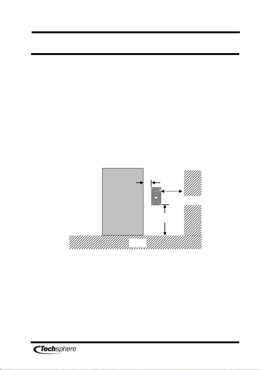
Do not install the VP-II Scanner where the floor is inclined.
Install the VP-II Scanner at a height of 1015-1045mm from the floor
and 100mm from the doorframe. If there is a wall beside the door
VP-II Scanner should be at least 200mm apart from the wall.
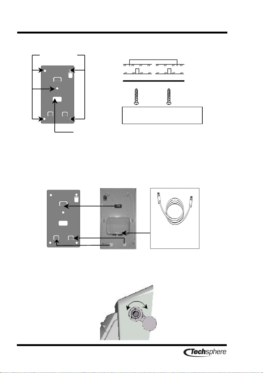
Put the bracket on the place for installing the VP-II Scanner and
make a hole after checking the hole location for cabling. Fix the
bracket on the wall using the bracket screws.
Power must be applied only after finishing all connections. Do not
perform any disconnection or connection after power is applied.
1
015
~1
045
mm
Door
100mm
200mm
Floor
Wall
6
After preparing the scanner cables connect the cables to the scanner
and then attach the scanner on the bracket. Make sure that the
scanner fit into the bracket all the way in. You may need some force.
When the scanner is fixed turn the security lock key clockwise and
then fix the scanner.
bracket
Bracket screws
Hole location for cabling
wall
Screw type: 4Φ×
××
×30 mm
RJ-45 cable
(4m)
Open
Close
7
Chapter 3 Installing the VP-II Controller
Install the Controller on the inner wall near enough to the VP-II
Scanner that it can be reached with the cables provided. The
Controller cable length should not exceed 4m. Select a place where
access for maintenance is convenient. Ensure that a power outlet is
near.
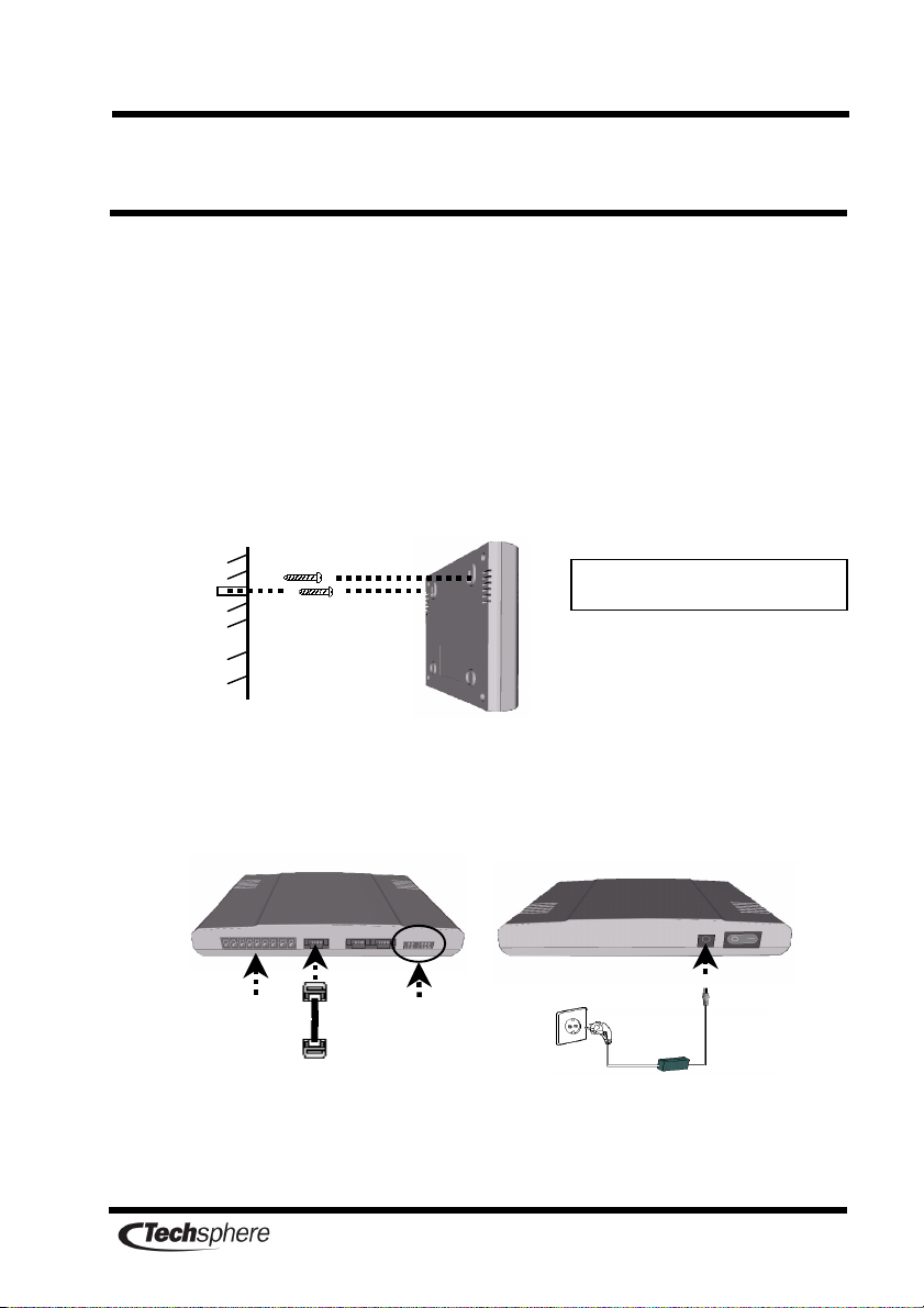
Make a hole in the wall for affixing the controller; then insert a screw
approximately two thirds of the way in. Fix the controller on the wall
by hooking it on the screw.
Connect the power cable and the controller cable. Ensure that the
connection cable is not exposed to the outside.
Screw type : 3
Φ
×
××
×
20mm
SMPS
DI S/W
VP-II Scanner
Door Lock
8
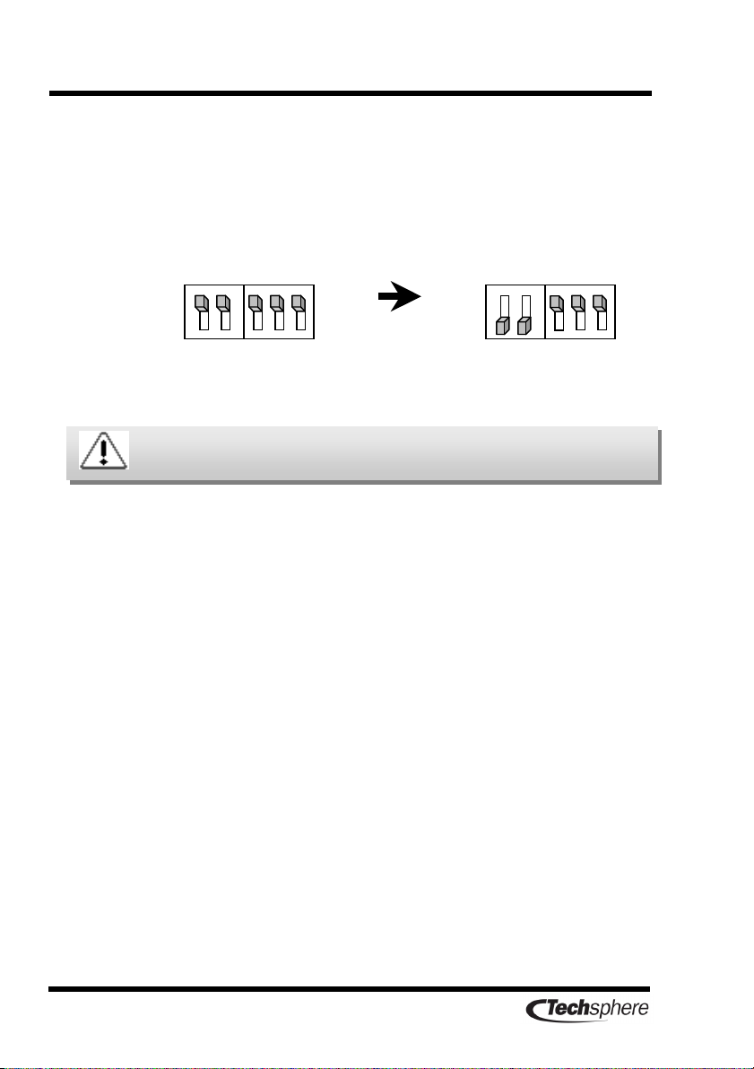
For a stand-alone VP-II system consisting of only one VP-II M
system (one Scanner and one Controller) set the dip switch of the
VP-II Controller as shown below. For extension to a network
environment (multiple Scanners and multiple Controllers) see the
VP-II NCU installation guide.
Factory setting Single V -II M
system mode
Please do not adjust settings unless you are an installer or a
technician.
Table of contents
Other Techsphere IP Access Controllers manuals


