Revised 03/25/2020 3
II. Accelerating Voltage
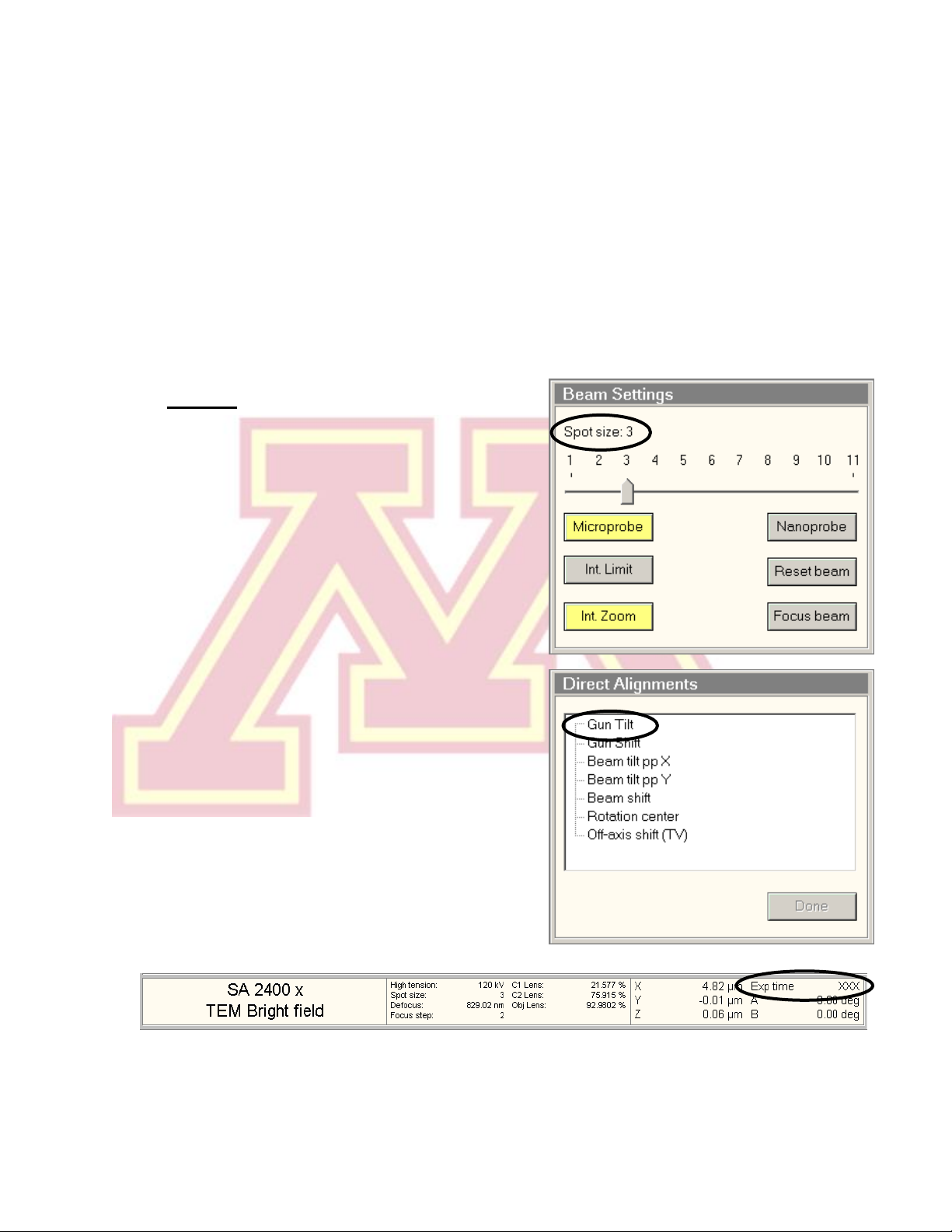
1.) If the “High Tension”button is lit and the displayed value reads 120 kV,
proceed to Section III.
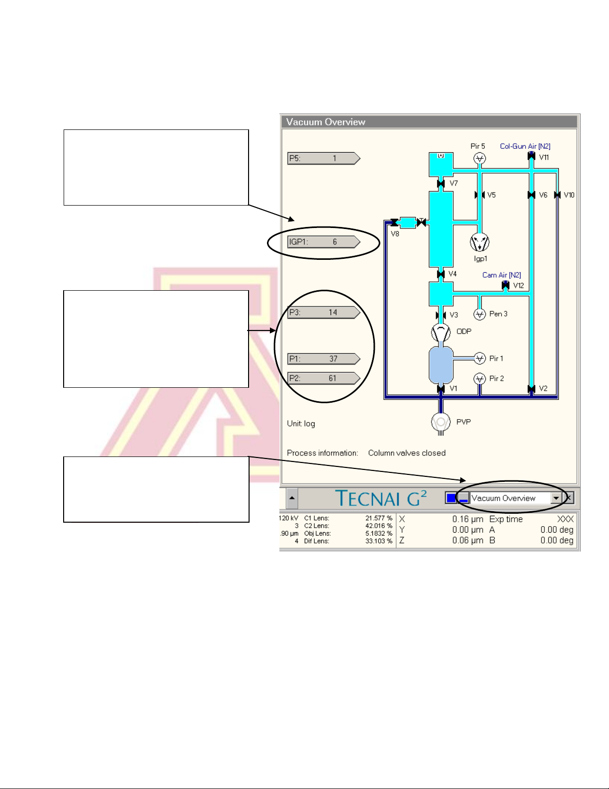
2.) The “High Tension" will be turned off (grey) for
the first user each day. IGP1 must read < 10
before proceeding (see Section I).
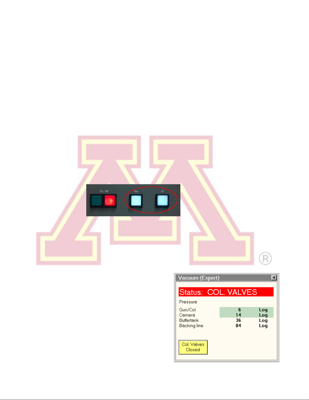
3.) If the “High Tension” button is unavailable (grey
with faded text), check that “HT” is lit on the
microscope control panel (Section I). If not,
press it once to light it.
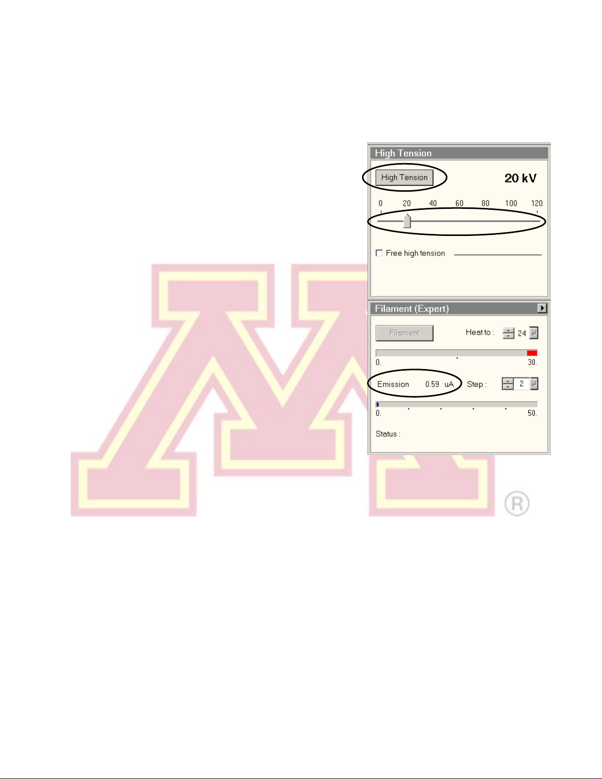
4.) Select 20 kV using the slider in the “High
Tension” control, then turn on the “High
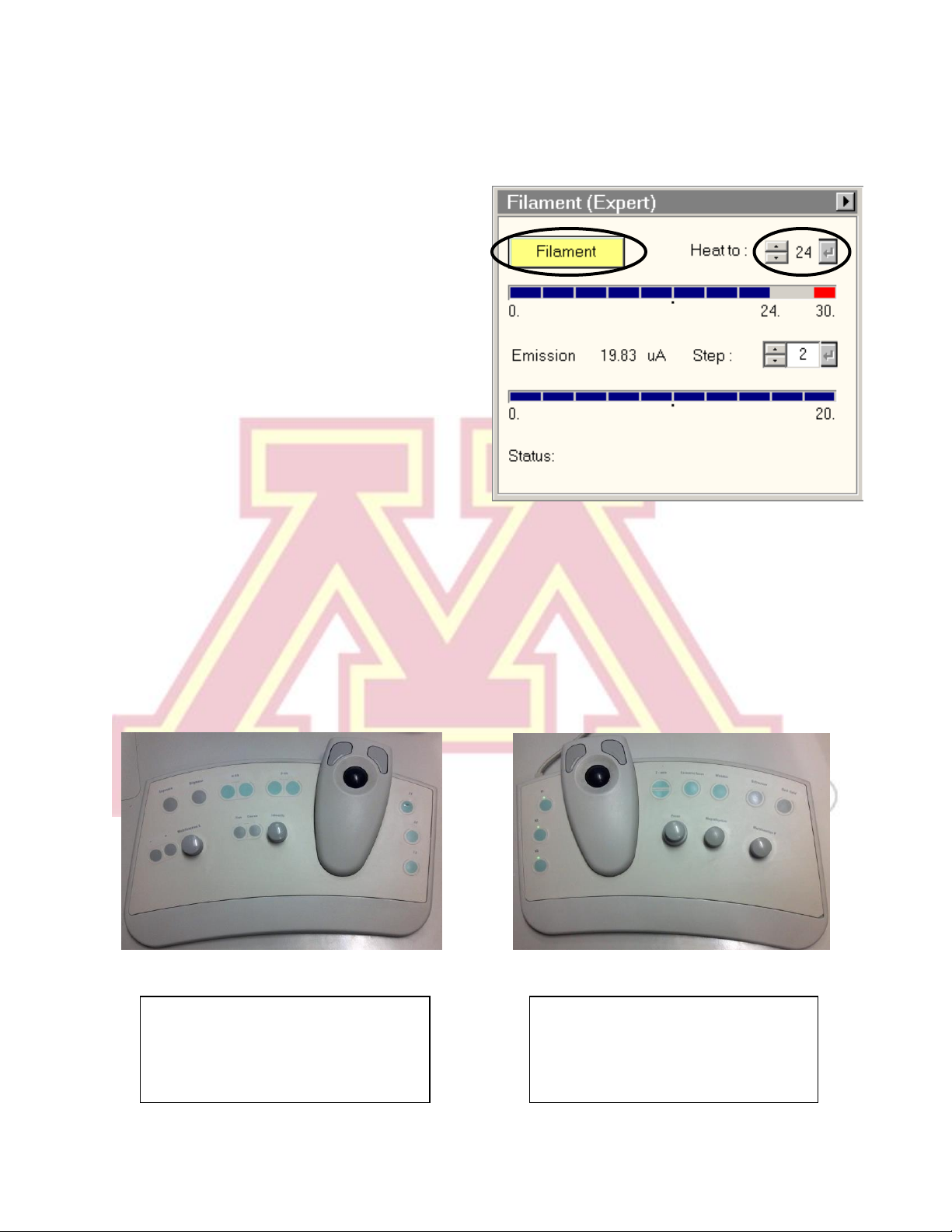
Tension” button. The emission current
(“Emission” in the “Filament” control) will spike
and then stabilize to ~0.5–1 µA.
5.) Wait 1–2 minutes before proceeding, and then
raise the slider to 40 kV. Continue in 20 kV
increments, waiting 1–2 min at each. If the
emission current remains high (>1–2 µA), return
to the previous step for several minutes.
Note: The HT may switch off and become disabled
when reaching 40 kV. If this occurs, simply press the main “HT” console button to
re-enable it (see Section I), click the “High Tension” again at 40 kV, and continue.
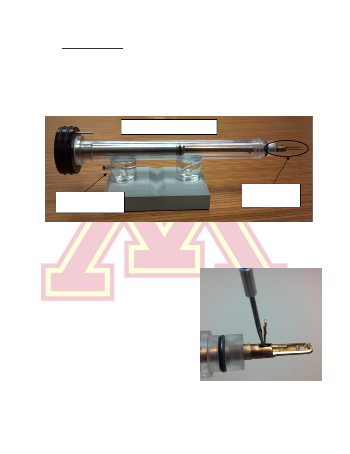
III. Specimen Loading and Holder Insertion/Removal
Note: the specimen holder, airlock, and compu-stage are made up of delicate,
precisely machined components. You should never have to exert significant
force during any step of this procedure. Doing so may result in serious
damage to the instrument or holder.
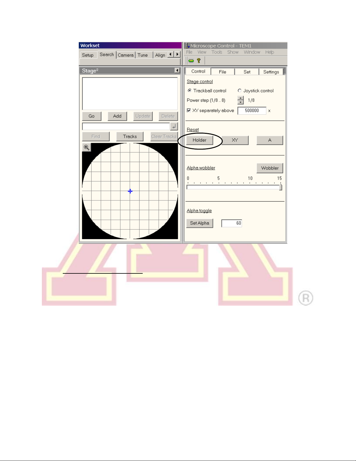
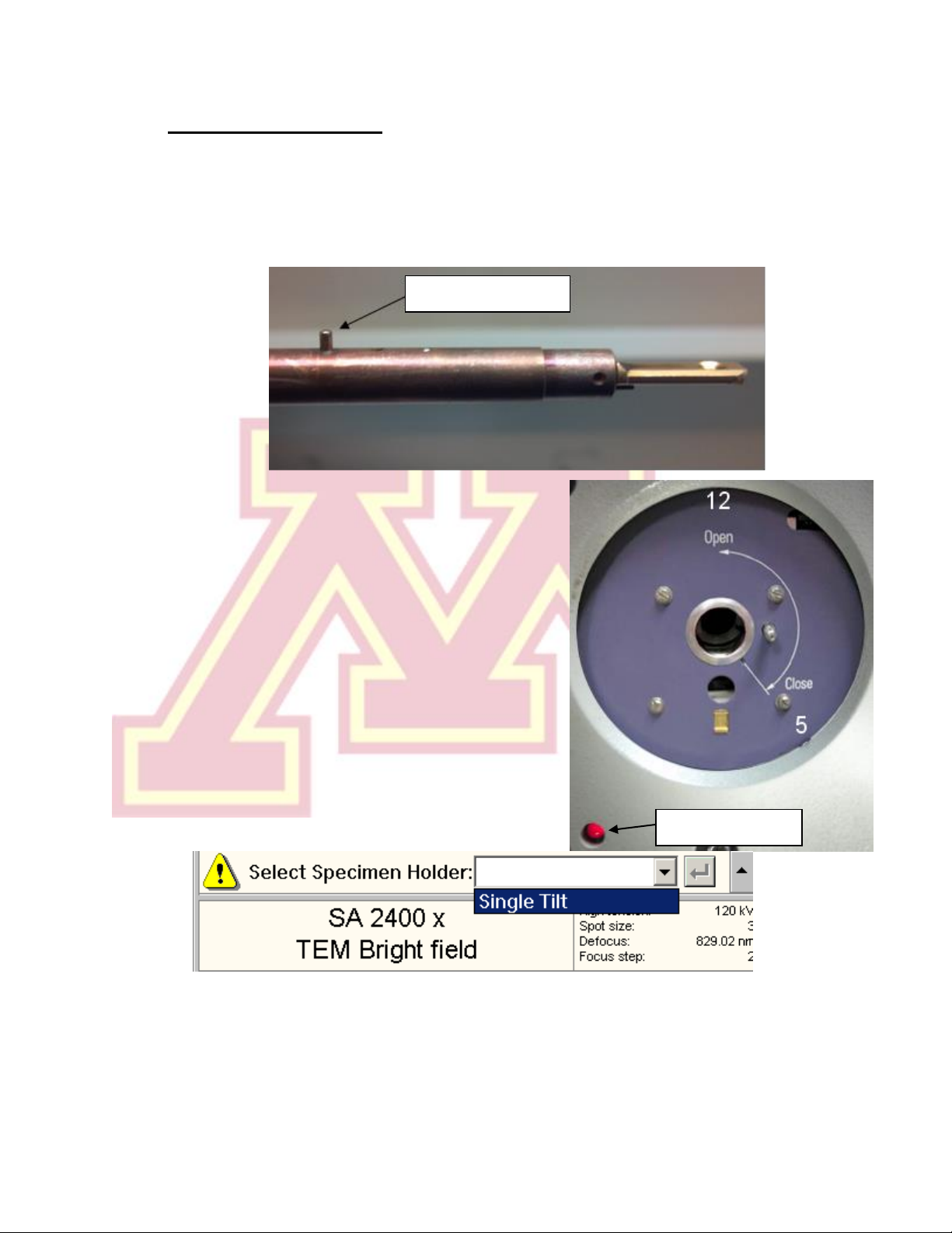
1.) Before inserting or removing the sample holder, make sure that the column
valves are closed, the objective aperture is not inserted, and the holder has
been reset. The stage is reset by using the “Search” tab, “Stage”(flapout),
“Reset: Holder”button.