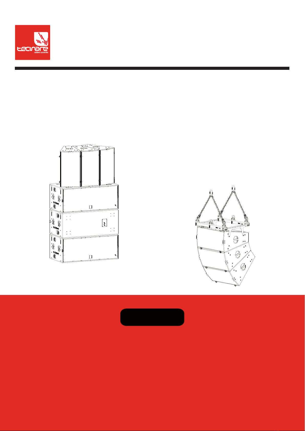
TECNARE ALIS Series User manual
Keep these important operating instructions.
Check www.tecnare.com for updates.
Rigging Assembly Guide
ALIS Series
ALIS12 / ALIS15
Version 1.5

1

Rigging Assembly Guide
2
General Information
ALIS_Series Rigging Assembly
Ver.: 1.5_UK 01/2019
©EXEL ACOUSTICS SL; all right reserved
The information contained in this manual has been
carefully checked for accuracy, at the time of going to
press, however no guarantee is given with respect to
the correctness.
Exel Acoustics SL accepts no responsibility for any
errors or inaccuracies that may appear in this manual
or the products and software described in it. Technical
specifications, dimensions, weights and properties do
not represent guaranteed qualities. As manufacturers
we reserve the right to make alterations and
modifications within the framework of legal provisions,
as well as changes aimed at improving quality.
EXEL ACOUSTICS SL
CL Encinar, 282 – Pol. Ind. Monte Boyal
45950 Casarrubios del Monte (Toledo) Spain
Phone: (+34) 918 170 110 Fax:
e-mail: support@tecnare.com www.tecnare.com

3
IMPORTANT SAFE INSTRUCTIONS
Before using our product, be sure to carefully read the manual and safe Instructions. Keep this document with the device all
time.
1 Read these instructions.
2 Keep these instructions.
3 Heed all warnings.
4 Follow all SAFETY INSTRUCTIONS as well
DANGER and OBLIGATION warnings.
5 Only use attachments / accessories
specified by the manufacturer.
6 SAFETY STATEMENT FOR RIGGING. This
Statement assumes that the owners and/or
users are familiar with the rigging techniques
and safety recommendations outlined in this
manual. Many issues of crucial concern,
such as the determination of
appropriateness and condition of venue
rigging points, cannot be addressed here.
Therefore, the user must assume all
responsibility for the appropriate use of
Rigging systems in any particular location or
circumstance.
7 PERSONNEL HEALTH AND SAFETY.
During installation and set-up personnel
should wear protective headgear and
footwear at all times. Under no
circumstances personnel should climb on
the loudspeaker assembly.
8 INSPECTION AND MAINTENANCE. The
rigging systems are an assembly of
mechanical devices, and are therefore
subject to wear and tear over prolonged use,
as well as damage from corrosive agents,
extreme impact, or inappropriate use.
Because of the safety issues involved, all
system components must be inspected
before use in order to detect any possible
defects.
9 LOAD RATING AND SPECIFICATIONS.
Load capacity and setup safety limits when
flying or stacking a loudspeaker assembly
should be strictly followed according to the
instructions outlined in this manual. Verify
that the Working Load Limit (WLL) of the
suspension points, chain hoist and all
additional hardware rigging accessories is
respected.
10 LOCAL REGULATIONS. The suspension of
large, heavy objects in public places is
subject to numerous laws and regulations at
the national/federal, state/provincial, and
local levels. It is the user’s responsibility to
verify that any overhead suspension of
TECNARE systems has been made in
accordance with all applicable local
regulations in any particular circumstance or
venue conforms to all applicable laws and
regulations in force at the time.
11 FLYING A LOUDSPEAKER SYSTEM
Always verify that nobody is standing
underneath the loudspeaker assembly when
it is being raised. As the system is being
raised check each individual component to
make sure that it is securely fastened to the
component above. Never leave the system
unattended during the installation process.
As a general rule, EXEL ACOUSTICS
recommends the use of safety slings at all
times.
12 STACKING A LOUDSPEAKER SYSTEM.
Do not ground stack the system on unstable
ground or platform. If the system is ground
stacked on a structure, platform, or stage
always check that the latter can support the
total weight of the system. As a general rule,
EXEL ACOUSTICS recommends the use of
safety straps at all times
13 When a loudspeaker assembly is deployed
in an open air environment, wind effects
should be taken into account. Wind can
produce dynamic stress to the rigging
components and suspension points. If the
wind force exceeds 6 B (Beaufort scale) it is
highly recommended to lower down and/or
secure the loudspeaker assembly.
14 REPLACEMENT PARTS. Any component
found to be defective, or any safety-related
component you even suspect might be
defective, should be replaced with the
equivalent, approved part. Parts specific to a
rigging system should be ordered directly
from Exel Acoustics. No attempt should be
made to substitute what appears to be
equivalent or “mostly the same” generic
replacements. Therefore, EXEL
ACOUSTICS is not responsible for problems
caused by components that were not
supplied by EXEL ACOUSTICS.
Introduction
4
SYMBOLS USED
Important operating
instructions Additional
information
OBLIGATION.
This instructions
must be strictly
followed
Pour indequer important
Instructions Information
complémentaire
Obligation. Cela
doit être
strictement
instructions Suivi
Wichtige
Betriebsanweisung
oder
Gebrauchsanleitung
sanleitung
Informationen.
Zusätzliche
Informationen
Pflicht. Diese
Anweisungen
müssen strikt
befolgt
Importantes
instrucciones operativas Información
complementaria
Obligación. Estas
instrucciones
deben ser
estrictamente
seguidas

Introduction
5
DECLARACIÓN DE CONFORMIDAD
DECLARATION OF CONFORMITY
EXEL ACOUSTICS SL
CL Encinar, 282. Polígono Industrial Monte Boyal. 45950 – Casarrubios del Monte (Toledo),
España (Spain).
Declara que los siguientes productos:
▪Pickup Plate THV-ALIS12/THV-ALIS15
▪Top Grid TTG ALIS12/THV-ALIS15
▪Array Frame TAF-ALIS12/TAF-ALIS15
▪Wooden Dolly TWD-ALIS12/TWD-ALIS15
▪TALBX12 Bar/ TALBX12 Bar
▪TA12-SMB Socket Mounting Bracket
▪TecB004
cumplen con las directivas:
Declare under our sole responsibility that devices
▪Pickup Plate THV-ALIS12/THV-ALIS15
▪Top Grid TTG ALIS12/TTG-ALIS15
▪Array Frame TAF-ALIS12/TAF-ALIS15
▪Wooden Dolly TWD-ALIS12/TWD-ALIS15
▪TALBX12 Bar/ TALBX12 Bar
▪TA12-SMB socket Mounting Bracket
▪TecB004
comply with relating Directives:
(1) Directiva 2006/42/CE relativa a las máquinas.
(2) Norma UNE-EN ISO 12100:2012 Relativa a la seguridad de las máquinas.
(3) RD 1644/2008
(1) Machinery Directive 2006/42/EC
(2) Mechanical Safety UNE-EN ISO 12100:2012 (Applied in Spain)
(3) RD 1644/2008 (applied in Spain)

Table of Contents
6
Table of Contents
IMPORTANT SAFE INSTRUCTIONS......................................................................................... 3
DECLARACIÓN DE CONFORMIDAD........................................................................................5
1INTRODUCTION.................................................................................................................. 7
1.1 Welcome to Tecnare®.................................................................................................. 7
1.2 ALIS Series System Components................................................................................8
2ARRAY CONFIGURATIONS .............................................................................................11
2.1 Cabinet connection using two TALBX15 bars ...........................................................11
2.2 Horizontal array with THV-ALIS Series......................................................................13
2.3 The TecB004 Spreader Bar.......................................................................................16
2.4 Vertical array with TTG-ALIS15.................................................................................18
2.5 The TAF-ALIS Series for fixed installations...............................................................21
3SUSPENSION OF VERTICAL ARRAY WITH TTG-ALIS15...........................................25
3.1 Modelling and inspection ...........................................................................................25
3.2 The TTG-ALIS15 grid.................................................................................................25
3.3 Secondary safety point ..............................................................................................27
4TA12-SMB SOCKET MONTAIN.......................................................................................30
4.1 Possible angles on ALIS12 using TS12-SMB............................................................32
5FC-ALIS SERIES...............................................................................................................33
6General Dimensions ........................................................................................................34
7Service, Inspection & Maintenance..............................................................................37
7.1 General Service .........................................................................................................37
7.2 Replacement components .........................................................................................37
7.3 Contacting Tecnare....................................................................................................37

Introduction
7
1INTRODUCTION
1.1 Welcome to Tecnare®
Thank you for choosing the high-quality Tecnare®ALIS Series R2 “Adaptative
Loudspeaker Integrate point Source”, “Made in Spain” from EXEL ACOUSTICS SL.
Please spare a little time to study the contents of this manual, so that you obtain the
best possible performance from this unit.
This user manual contains essential information for rigging and deploying ALIS
Series loudspeakers to their full capability. Assembly concept for ALIS Series
loudspeakers is the same for both ALIS12 and ALIS15 enclosures so we will show you
the information in this guide taking as reference ALIS15 enclosure except in those
particular accessories in which there are assembly differences between both models.
All Tecnare®products are carefully engineered for world-class performance and
reliability.
If you would like further information about this or any other Tecnare®product, please
contact us. We look forward to helping you in the near future.
As part of a continuous evolution of techniques and standards, Exel Acoustics
SL as manufacturer of Tecnare®products reserve the right to change the specifications
of its products and the content of its documents without prior notice.
Updates and supplementary information are available on the Tecnare®website:
http://www.tecnare.com
Tecnare Technical Support is available at:
•(T): +34 918 170 110 - +34 918 171 001
•(e-mail): support@tecnare.com
Thank you again for placing your confidence in Tecnare®products.

Rigging Assembly Guide
8
1.2 ALIS Series System Components
This assembly guide document the rigging and transport options THV-ALIS12, THV-
ALIS15, TTG-ALIS12, TTG-ALIS15, TAF-ALIS12, TAF-ALIS15, TALBX-12, TALBX-15,
TA12-SMB, TecB004 and TWD-ALIS12, TWD-ALIS15 available for ALIS12 and ALIS15 in the
form of flown or stacked vertical arrays.
The system approach developed by EXEL ACOUSTICS SL for the Tecnare®ALIS
Series cabinets consists of the elements needed to fully take advantage of the possible
configurations and optimize the system. The main components of the system are:
▪ALIS12: Adaptative Loudspeaker Integrate point Source
▪ALIS15: Adaptative Loudspeaker Integrate point Source
▪THV-ALIS12: Pickup Array Plate for ALIS12
▪THV-ALIS15: Pickup Array Plate for ALIS15
▪TTG-ALIS12: Top Rigging Bar Element for ALIS12
▪TTG-ALIS15: Top Rigging Bar Element for ALIS15
▪TAF-ALIS12: Array Frame for linking cluster of 2 units of ALIS12
▪TAF-ALIS15: Array Frame for linking cluster of 2 units of ALIS15
▪TALBX-12: Coupling bar which makes a connection of adjacent ALIS12 enclosures
in both vertical and horizontal
▪TALBX-15: Coupling bar which makes a connection of adjacent ALIS15 enclosures
in both vertical and horizontal
▪TA12-SMB: Pole mount socket for 1 x ALIS12 enclosure.
▪TecB004: Load Spreader Bar. It used to suspend two THV-ALIS15 pickup plates
from a single point for hanging arrays of up six ALISs cabinets. It should use with 1
x 2t and 4 x 0,75t shackles. It has a WLL of six cabinets
▪TWD-ALIS12: Removable front wooden transport dolly for transport one ALIS12
cabinet
▪TWD-ALIS15: Removable front wooden transport dolly for transport one ALIS15
cabinet
▪FUND-ALIS12: Protective soft cover professional version made of black polyester
with inner foam to cover for transportation and storage one ALIS12 cabinet
▪FUND-ALIS15: Protective soft cover professional version made of black polyester
with inner foam to cover for transportation and storage one ALIS15 cabinet
▪FC-ALIS12: Flight-case designed to ship a 1xALIS12 or 2xALIS12 cabinet. It
contain foam insert to prevent enclosure movement.
▪FC-ALIS15: Flight-case designed to ship a 1xALIS15 or 2xALIS15 cabinet. It
contain foam insert to prevent enclosure movement.
▪T-44/48: Advanced System Amplifier
▪System Engineer: Remote control software for amplifier
OTHER ALIS SYSTEM COMPONENTS
All the other components of the system are presented in the ALIS Series user manual,
document intended to describe the operating modes and the loudspeaker connection.
Operation Manual
9
Rigging Example

Rigging Assembly Guide
10
THV-ALIS15
THV-ALIS12
TTG-ALIS15
TTG-ALIS12
Main components involved in the rigging system of ALIS Series enclosures
TA12-SMB
TecB004
Operation Manual
11
2ARRAY CONFIGURATIONS
The ALIS loudspeaker has got a complete collection of rigging, flying, and mounting
options. Comprised of rugged, reliable, and easy-to-configure components, lets you deploy
ALIS loudspeakers as arrays at fixed angles to take full advantage of their directional design.
The top and bottom sides for the ALIS cabinets include threaded metric holes (for M8 screws)
for easy connection to rigging and third-party mounting options.
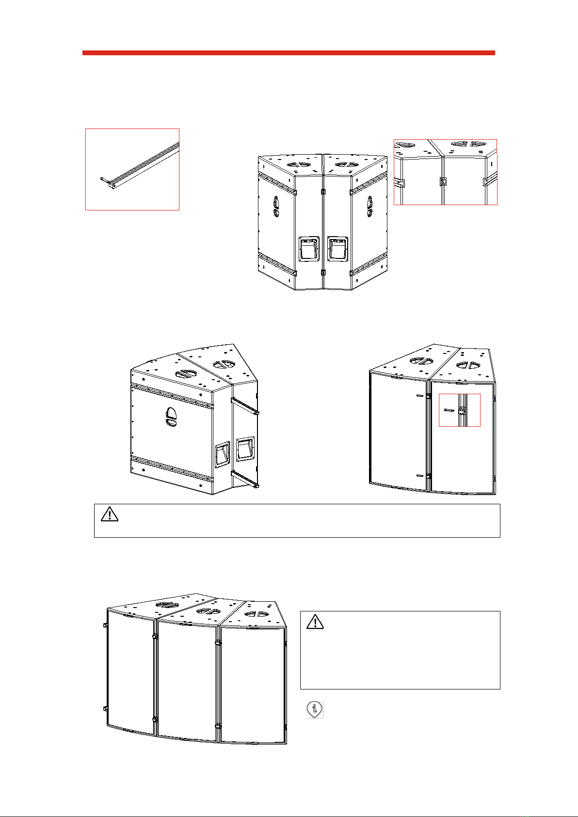
2.1 Cabinet connection using two TALBX15 bars
Two or more ALIS15 cabinets can be coupled together using the coupling bar and quick
release pin. Use a flat surface for this operation.
1 Place the enclosures carefully to a vertical position using the top/bottom recessed
handles.
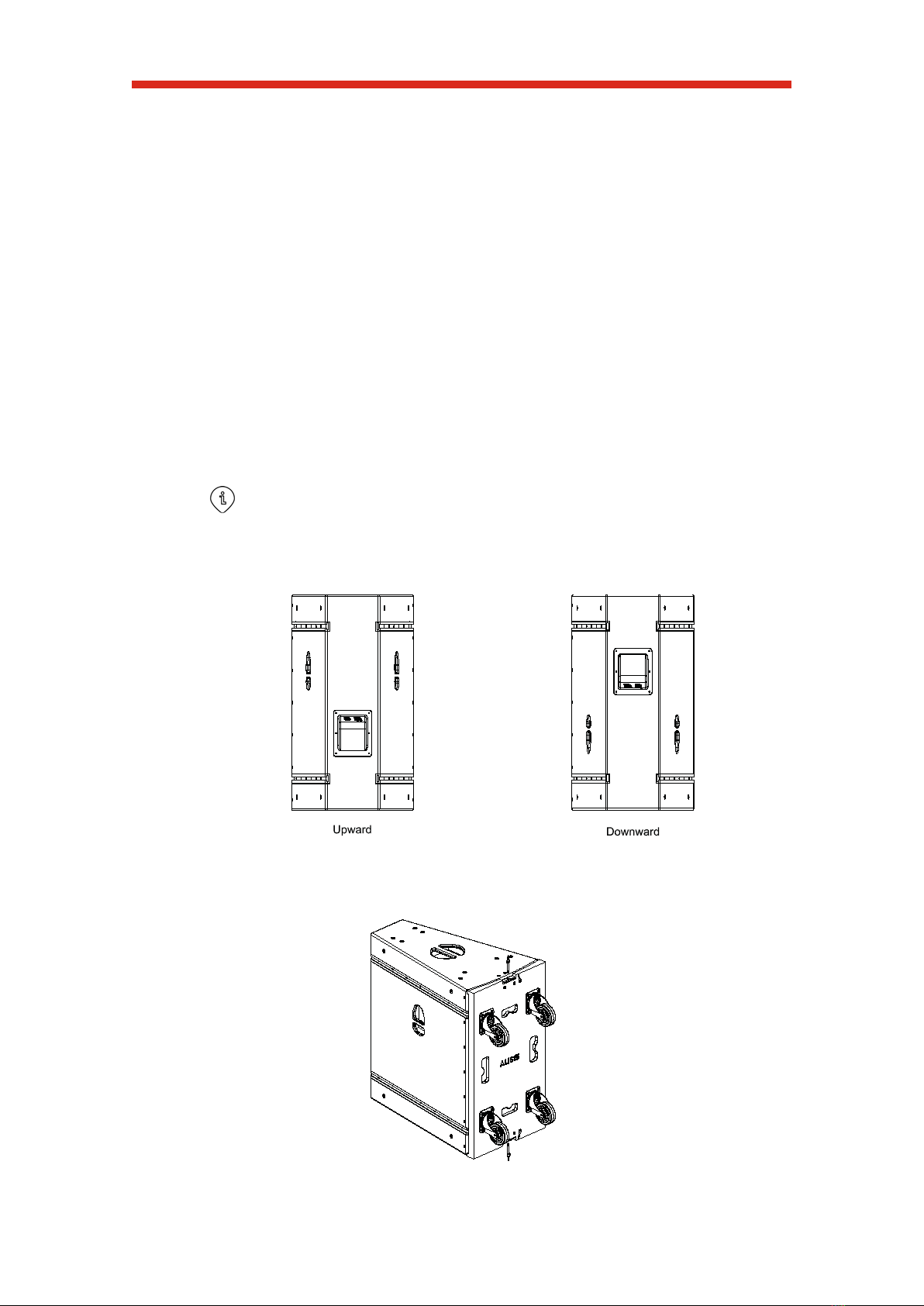
Specific to horizontal arrays
The ALIS15 enclosure could be used with the horn directed upwards or downwards.
Place the enclosures on the desired position. Check that all ALIS15 enclosures are
physically oriented in the same manner.
Fig.1
2 Remove the TWD-ALIS15 dolly boards. Take the top/bottom safety quick-release pins
off from the TWD-ALIS15 hitching pins.
Fig.2
Rigging Assembly Guide
12
3 Remove the front pins of each coupling bar. Fig. 3
4 Located the ALIS15s next to each other and align the adjacent the rails so they are as
close as possible to each other. Fig.4
5 From the rear, slide the coupling bars inwards and re-attaching the front quick-release
pins. Fig.5
CAUTION: Injury hazard. Please pay close attention when the coupling bars are sliding
so as not to pinch your fingers.
6 To link one more enclosure, take the group of two enclosures joined before and follow
the instructions describe since point 4.
CAUTION: Routine maintenance
inspections of the ALIS15 should include a
check of all quick-release pins. Press and
release the knob and check the internal ball
come in and out easily. If not you should
get a new quick release pin.
The use of security gloves and shoes
are highly recommended for these
operations
Fig. 3
Fig. 4
Fig. 5
Fig. 6
Fig.7 Assembly ready for the next procedure

Operation Manual
13
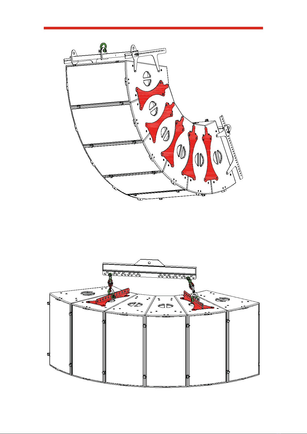
2.2 Horizontal array with THV-ALIS Series
The optional THV-ALIS Series pickup plate allows lifts ALIS horizontal arrays with uptilt or
downtilt. A single pickup plate supports 1-4 loudspeakers. Two pickup plates and the accessory
TecB004 universal Fly Bar support 5-6 loudspeakers. The pickup plate comes with M8 bolts,
and washers for securing the plate to the ALIS cabinet. It also can be using as an extra cabinet
connection.
The THV-ALIS12 has got a row of 8 hanging points in the middle of the plate. When
suspending the pickup plate from a single hanging point, the location of hanging point
determines the uptilt or downtilt of the suspended ALIS12s.
Fig.8a THVALIS12 Rigging hole on which securing the shackle
The THV-ALIS15 has got a row of 12 hanging points in the middle of the plate. When
suspending the pickup plate from a single hanging point, the location of hanging point
determines the uptilt or downtilt of the suspended ALIS15s.
Fig.8b THVALIS15 Rigging hole on which securing the shackle
About tilt angle
As many variables can affect to the tilt angle, to be sure about it, we recommend use a
laser/inclinometer device for this operation. Refer to our Tecnare support team if you have got
any question about how to do it. support@tecnare.com
Rigging Assembly Guide
14
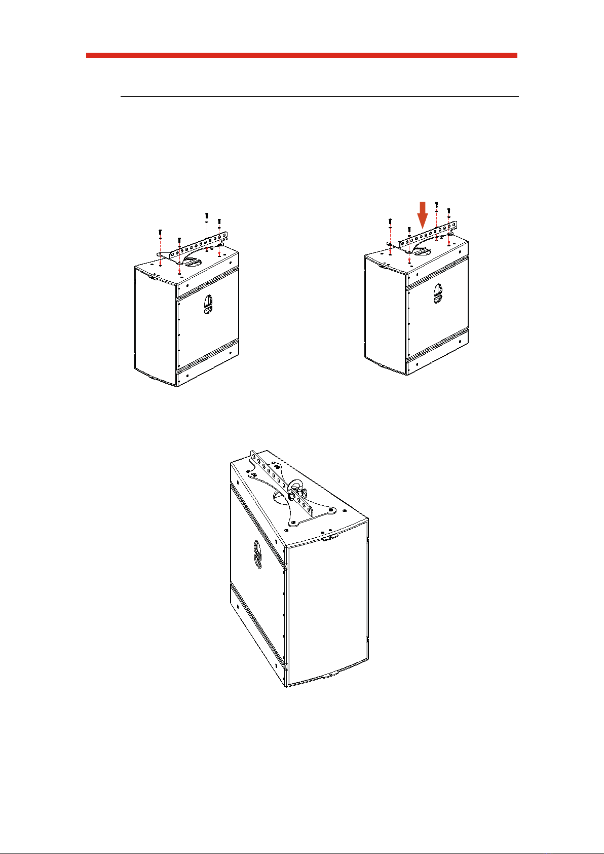
Procedure
1 Place the enclosures carefully to a
vertical position using the
top/bottom recessed handles, with
the horn directed upwards or
downwards. Remove the screws
indicates in Figure 9.
2 Attach the THV-ALIS15 pickup
plate over the enclosure and
screw it with the included screws
in the same position shown in
Figure 10.
3 The final position is shown in the figure 11.
Fig.11 ALIS15 in horizontal array ready to be flown
Fig. 9
Fig. 10

Operation Manual
15
The following configurations are allowed:
6x ALIS15 + 2x THVALIS15; 5x ALIS15 + 2x THVALIS15; 4x ALIS15 + 2 x THVALIS15;
4x ALIS15 + 1 x THVALIS15; 3x ALIS15 + 2x THVALIS15; 3x ALIS15 + 1x THVALIS15;
2x ALIS15 + 1x THVALIS15 and ALIS15 + THVALIS15
Fig.12 ALIS15 in horizontal array
When an array is suspend with two THV-ALIS15 pickup plates, two pick points for each pickup
plate can be using.

Rigging Assembly Guide
16
2.3 The TecB004 Spreader Bar
The optional TecB004 spreader bar can suspend two THV-ALIS Series pickup plates from
a single motor point. Under no circumstances is a bridled suspension chain allowed.
Seventeen hanging points are provided at each end of the spreader bar to adjust the
spread between the pickup plates. This connection can be made using two 0,75t shackles per
side. Use a 2t shackle for the single hoist point.
Procedure
1. First, you must to set the optional TecB004 spreader bar to both THV-ALIS15 pickup
plate
a. Pass the Ω-shape or U-shape of
one of the shackles through a connecting
link shackle or directly to the shackle
attached to one of the THV- ALIS15.
b. Secure the shackle to the TecB004
spreader bar, threading its pin through the
spreader bar hole previously chooses.
When a safety pin is used, ensure the split
pin is located correctly and secured.
c. Repeat the previous step on the
other side of the TecB004 spreader bar for
the other THV-ALIS15.
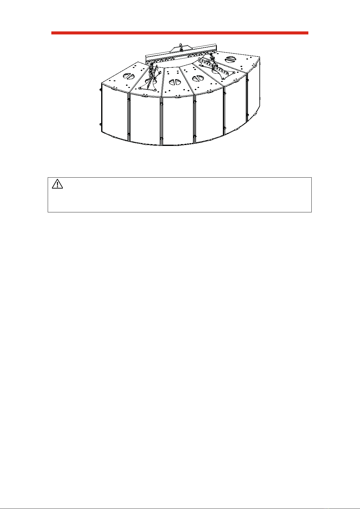
2. Second, Place the 2T shackle in the upper hole of TecB004 spreader bar.
Operation Manual
17
Fig. 13 Six ALIS15s Horizontal Array with two THV-ALIS15s suspended from the TecB004 Spreader Bar
CAUTION: Routine maintenance inspections of the shackles should include a check for
wear inside the shackle, check the body for distortion and check for the wear on the shackle pin.
Never Replace a Shackle pin with a Bolt. The Load will bend the bolt.

Rigging Assembly Guide
18
2.4 Vertical array with TTG-ALIS15
The ALIS15 loudspeaker array can be suspends vertically using the optional TTG-ALIS15.
Before starting to assemble the array, you must define the orientation of the HF section of the
cabinets.
The ALIS15 cabinets have an asymmetric design. To enable a symmetrical setup for
stereo systems, one’s cabinet orientation may be reversed. This grid enables building “left” or
“right” configurations. The TTG-ALIS15 is attached to one of the enclosure at the top of the
assembly, depending on enclosures' orientation.
The cabinet's connector plate at the rear may serve to indicate the orientation of the HF
Section, as you can see in the graphic lower.
HF SECTION
HF SECTION
HF RIGHT CONFIGURATION HF LEFT CONFIGURATION
ALIS15 in left and right configuration
The TTG-ALIS15 comes with four quick-release pins for securing the ALIS15 to the grid.
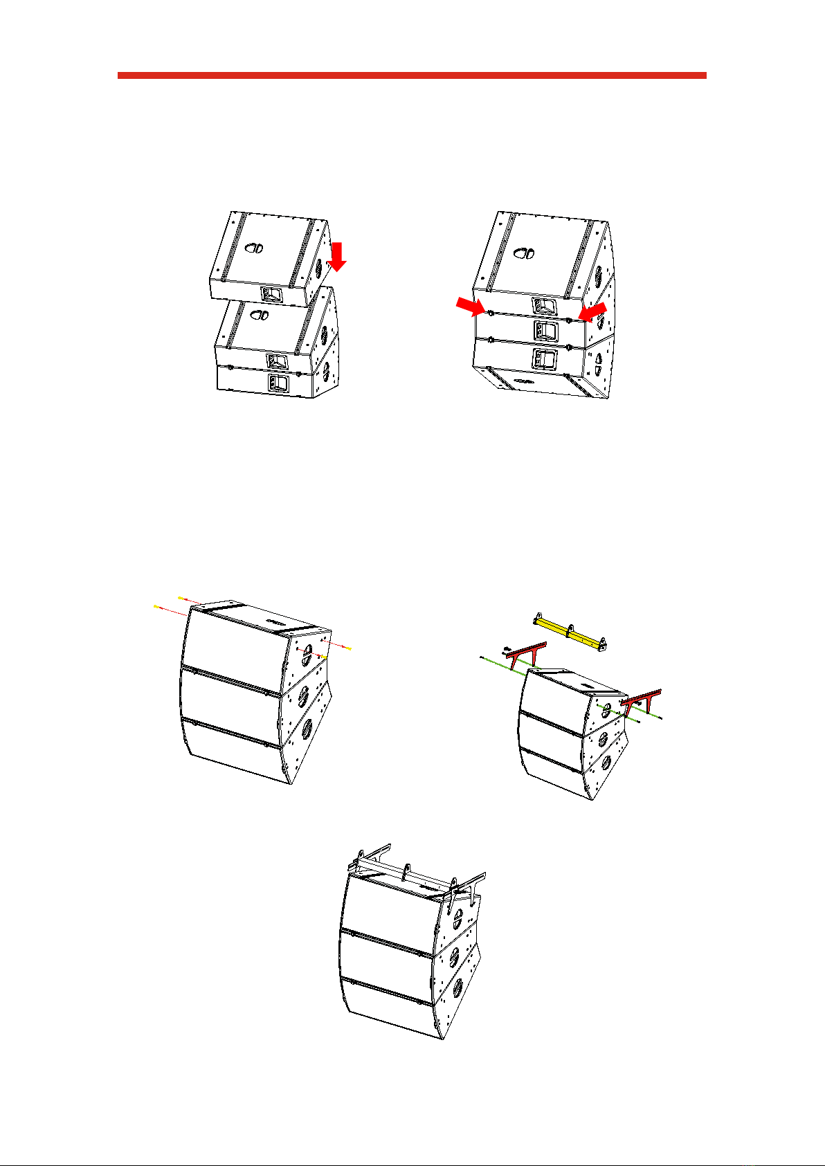
Procedure
1 Firstly, you must identify the
enclosure with the orientation
desired and then you will place the
first two enclosures, one above
the other on a flat surface, as it
shown in Fig.15
2 The adjacent rigging rails should
be perfectly aligned.
Two TALBX15 BARs must be slid
from the rear of array and secured
with its quick-release pin at both
back and front. Fig. 16
Fig. 15
Fig. 16
Operation Manual
19
3 To assemble more enclosures, take the group of two enclosures joined before and
follow the steps described on the point 1 and 2. (Figure 17 and 18). The optional TTG-
ALIS15 vertical grid was designed to suspend up to six units.
Remember to repeat the assembly process of slid the couple of TALBX15 bars and to
be sure of secure them with the quick-release pins
4 Finally, assemble the TTG-ALIS15 on the top enclosure.
a. Remove the screws indicate in
figure 19.
Fig. 19
b. Following attach the TTG-ALIS15's
side plates and screw with the included
screws in the same position shown in the
figure 20. After that you will mount the TTG-
ALIS15 pickup bar like the figure 20.
Fig. 20
Fig. 21 TTG-ALIS15 Vertical Grid with three ALIS15s
Fig. 17
Fig. 18
Other manuals for ALIS Series
2
This manual suits for next models
2
Table of contents
Other TECNARE Speakers manuals

TECNARE
TECNARE IBZA Series User manual

TECNARE
TECNARE Versatile V Series User manual

TECNARE
TECNARE IBZA Series User manual

TECNARE
TECNARE ALIS Series User manual

TECNARE
TECNARE IBZA Series User manual

TECNARE
TECNARE IBZA Series User manual

TECNARE
TECNARE E- Series User manual

TECNARE
TECNARE ALIS Series User manual

TECNARE
TECNARE PCCbox Series User manual


