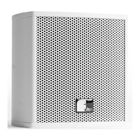
TECNARE E- Series User manual

Keep these important operating instructions.
Check www.tecnare.com for updates.
Rigging Assembly Guide
E- Series
E6/E8
Version 1.0

1

Rigging Assembly Guide
2
General Information
E6/E8 Rigging Assembly
Ver.: 1.0_UK_ES 01/2018
©EXEL ACOUSTICS SL; all right reserved
The information contained in this manual has been
carefully checked for accuracy, at the time of going to
press, however no guarantee is given with respect to
the correctness.
Exel Acoustics SL accepts no responsibility for any
errors or inaccuracies that may appear in this manual
or the products and software described in it. Technical
specifications, dimensions, weights and properties do
not represent guaranteed qualities. As manufacturers
we reserve the right to make alterations and
modifications within the framework of legal provisions,
as well as changes aimed at improving quality.
EXEL ACOUSTICS SL
CL Encinar, 282 – Pol. Ind. Monte Boyal
45950 Casarrubios del Monte (Toledo) Spain
Phone: (+34) 918 170 110 Fax:
e-mail: support@tecnare.com www.tecnare.com

3
IMPORTANT SAFE INSTRUCTIONS
Before using our product, be sure to carefully read the manual and safe Instructions. Keep this document with the device all
time.
1 Read these instructions.
2 Keep these instructions.
3 Heed all warnings.
4 Follow all SAFETY INSTRUCTIONS as well
DANGER and OBLIGATION warnings.
5 Only use attachments / accessories specified by
the manufacturer.
6 SAFETY STATEMENT FOR RIGGING. This
Statement assumes that the owners and/or users
are familiar with the rigging techniques and safety
recommendations outlined in this manual. Many
issues of crucial concern, such as the
determination of appropriateness and condition of
venue rigging points, cannot be addressed here.
Therefore, the user must assume all responsibility
for the appropriate use of rigging systems in any
particular location or circumstance.
7 PERSONNEL HEALTH AND SAFETY. During
installation and set-up personnel should wear
protective headgear and footwear at all times.
Under no circumstances personnel should climb on
the loudspeaker assembly.
8 INSPECTION AND MAINTENANCE. The rigging
systems are an assembly of mechanical devices,
and are therefore subject to wear and tear over
prolonged use, as well as damage from corrosive
agents, extreme impact, or inappropriate use.
Because of the safety issues involved, all system
components must be inspected before use in order
to detect any possible defects.
9 LOAD RATING AND SPECIFICATIONS. Load
capacity and setup safety limits when flying or
stacking a loudspeaker assembly should be strictly
followed according to the instructions outlined in
this manual.
10 LOCAL REGULATIONS. The suspension of large,
heavy objects in public places is subject to
numerous laws and regulations at the
national/federal, state/provincial, and local levels.
It is the user’s responsibility to verify that any
overhead suspension of TECNARE systems has
been made in accordance with all applicable local
regulations in any particular circumstance or venue
conforms to all applicable laws and regulations in
force at the time.
11 FLYING A LOUDSPEAKER SYSTEM Always
verify that nobody is standing underneath the
loudspeaker assembly when it is being raised. As
the system is being raised check each individual
component to make sure that it is securely
fastened to the component above. Never leave the
system unattended during the installation process.
As a general rule, EXEL ACOUSTICS
recommends the use of safety slings at all times.
12 STACKING A LOUDSPEAKER SYSTEM. Do not
ground stack the system on unstable ground or
platform. If the system is ground stacked on a
structure, platform, or stage always check that the
latter can support the total weight of the system. As
a general rule, EXEL ACOUSTICS recommends
the use of safety straps at all times
13 When a loudspeaker assembly is deployed in an
open air environment, wind effects should be taken
into account. Wind can produce dynamic stress to
the rigging components and suspension points. If
the wind force exceeds 6 B (Beaufort scale) it is
highly recommended to lower down and/or secure
the loudspeaker assembly.
14 REPLACEMENT PARTS. Any component found to
be defective, or any safety-related component you
even suspect might be defective, should be
replaced with the equivalent, approved part. Parts
specific to a rigging system should be ordered
directly from Exel Acoustics. No attempt should be
made to substitute what appears to be equivalent
or “mostly the same” generic replacements.
Therefore, EXEL ACOUSTICS is not responsible
for problems caused by components that were not
supplied by EXEL ACOUSTICS.
15 SYMBOLS USED
Important operating
instructions
Additional
information
OBLIGATION.This
instructions must be
strictly followed
Pour indequer important
Instructions Information
complémentaire
Obligation. Cela doit
être strictement
instructions Suivi
Wichtige
Betriebsanweisung
oder
Gebrauchsanleitung
sanleitung
Informationen.
Zusätzliche
Informationen
Pflicht. Diese
Anweisungen
müssen strikt
befolgt
Importantes
instrucciones operativas
Información
complementaria
Obligación. Estas
instrucciones deben
ser estrictamente
seguidas

2
INSTRUCCIONES DE SEGURIDAD
Antes de usar nuestro producto, asegúrese de leer detenidamente el manual y las instrucciones de seguridad. Guarde este
documento con su aparato todo el tiempo.
1 Guarde estas instrucciones.
2 Preste atención a todas las advertencias.
3 Siga todas las INSTRUCCIONES DE
SEGURIDAD y las advertencias de PELIGRO y
OBLIGACIÓN.
4 Utilice solamente los accesorios especificados /
recomendados por el fabricante.
5 DECLARACION DE SEGURIDAD PARA EL
RIGGING.Esta declaración asume que los
propietarios / o usuarios están familiarizados con
las técnicas de rigging y las recomendaciones de
seguridad descritas en este manual. Problemas de
importancia crucial como la determinación de los
puntos de colgado del lugar no se pueden abordar
aquí. Por tanto, el usuario debe asumir toda la
responsabilidad por el uso apropiado de los
sistemas de Rigging en cualquier ubicación o
circunstancia particular.
6 SALUD Y SEGURIDAD PERSONAL.Durante la
instalación y montaje, el personal debe usar casco
y calzado de protección en todo momento. Bajo
ninguna circunstancia, el personal debe subir
encima del altavoz.
7 INSPECCIÓN Y MANTENIMIENTO. Los sistemas
de suspensión son elementos mecánicos y por
tanto sujetos a desgaste por el uso prolongado, así
como daños por agentes corrosivos, impactos
extremos o uso inapropiado. Debido a los
problemas de seguridad involucrados, los sistemas
deben inspeccionarse antes de su uso.
8 CAPACIDAD DE CARGA Y
ESPECIFICACIONES. Se debe seguir
estrictamente la capacidad de carga y los límites
de seguridad de la configuración del conjunto de
altavoces a volar o apilar de acuerdo a las
instrucciones de este manual.
9 REGULACIONES LOCALES. La suspensión de
objetos grandes y pesados en lugares públicos
está sujeta a numerosas leyes y regulaciones a
nivel nacional / federal, estatal / provincial y local.
Es responsabilidad del usuario verificar que
cualquier suspensión de sistemas TECNARE se
haya realizado de acuerdo con todas las
regulaciones locales y leyes vigentes en ese
momento.
10 VOLADO DE UN SISTEMA DE ALTAVOCES.
Verifique SIEMPRE que nadie está situado debajo
del conjunto de altavoces cuando se está
levantando. A medida que se eleva el sistema,
verifique cada componente individual para
asegurar que está bien sujeto al componente
anterior. Nunca deje el sistema desatendido
durante el proceso de instalación. Como regla
general, EXEL ACOUSTICS recomienda el uso de
eslingas de seguridad en todo momento.
11 APILADO DE SISTEMAS DE ALTAVOCES. No
apile el sistema en terrenos inestables. Si el
sistema se apila sobre plataforma, estructura o
escenario, compruebe siempre que este puede
soportar el peso total del sistema. EXEL
ACOUSTICS recomienda siempre el uso de
eslingas de seguridad en todo momento.
12 Cuando un sistema de altavoces se instala al aire
libre, se debe tener en cuenta los efectos del
viento. El viento puede producir un estrés dinámico
en los componentes del rigging y de los puntos de
suspensión. Si la fuerza del viento excede los 6B
(escala de Beaufort), se recomienda
encarecidamente descolgar y / o fijar el altavoz.
13 PIEZAS DE REPUESTO. Cualquier componente
que se encuentre defectuoso, o cualquier
componente relacionado con la seguridad que
sospeche que podría ser defectuoso, debe
reemplazarse por una pieza equivalente aprobada.
Las piezas específicas de un sistema de colgado
se deben pedir directamente a Exel Acoustics. No
debe hacerse ningún intento por sustituir lo que
parece ser equivalente o "casi el mismo"
reemplazo genérico. Por lo tanto, EXEL
ACOUSTICS no es responsable de los problemas
causados por componentes que no fueron
suministrados por EXEL ACOUSTICS.
14 SIMBOLOS USADOS
Important operating
instructions
Additional
information
OBLIGATION.This
instructions must be
strictly followed
Pour indequer important
Instructions
Information
complémentaire
Obligation. Cela doit
être strictement
instructions Suivi
Wichtige
Betriebsanweisung
oder
Gebrauchsanleitung
sanleitung
Informationen.
Zusätzliche
Informationen
Pflicht. Diese
Anweisungen
müssen strikt
befolgt
Importantes
instrucciones operativas
Información
complementaria
Obligación. Estas
instrucciones deben
ser estrictamente
seguidas

CONFORMITY/ CONFORMIDAD
3
DECLARACIÓN DE CONFORMIDAD
DECLARATION OF CONFORMITY
EXEL ACOUSTICS SL
CL Encinar, 282. Polígono Industrial Monte Boyal. 45950 – Casarrubios del Monte (Toledo),
España (Spain).
Declara que los siguientes productos:
▪E6/E8 U-Bracket
▪Soporte Regulable HG-1
▪Soporte de Techo HG-2
cumplen con las directivas:
Declare under our sole responsibility that devices
▪E6/E8 U-Bracket
▪HG-1 Single Point Bracket
▪HG-2 Ceiling Bracket
comply with relating Directives:
(1) Directiva 2006/42/CE relativa a las máquinas.
(2) Norma UNE-EN ISO 12100:2012 Relativa a la seguridad de las máquinas.
(3) RD 1644/2008
(1) Machinery Directive 2006/42/EC
(2) Mechanical Safety UNE-EN ISO 12100:2012 (Applied in Spain)
(3) RD 1644/2008 (applied in Spain)

Operation Manual
4
Table of Contents
IMPORTANT SAFE INSTRUCTIONS......................................................................................3
INSTRUCCIONES DE SEGURIDAD.......................................................................................2
DECLARACIÓN DE CONFORMIDAD .....................................................................................3
Table of Contents ..................................................................................................................4
1. Individual Components / Componentes Individuales...............................................5
1.1 Eyebolts / Cáncamo (Argolla) ...................................................................................5
1.2 U-Bracket / Soporte en “U” .......................................................................................5
1.3 HG-1 Single-point Bracket / Soporte regulable HG-1 ................................................5
1.4 HG-2 Ceiling Bracket / Soporte regulable de techo HG-2..........................................6
2. BG-E6/E8 Installation Instructions / Instalación BG-E6/E8 ....................................7
3. HG-1 Installation Instructions / Instalación HG-1 ....................................................8
4. HG-2 Installation Instructions / Instalación HG-2 ....................................................9
5. Flying with eyebolts Instructions / Colgado con cáncamos...................................11

Operation Manual
5
1. Individual Components / Componentes Individuales
Note: The accessories for E-6, E8, E10, E12 and E15 models are identical except for the U-Bracket.
Aviso: Los accesorios de montaje para los modelos de altavoces E-6, E-8, E-10, E-12 y E-15 son
idénticos, excepto por los soportes en “U”.
1.1 Eyebolts / Cáncamo (Argolla)
The Tecnare E-6 and E8 loudspeakers have 4 flying
points available for use with different Tecnare
accessories. These points are sealed with M8 screws.
One of these accessories is eyebolts. Flying with
eyebolts is economical and safe, and it is
recommended for fixed installations.
Los altavoces Tecnare E-6 y E8 tienen y puntos de
anclaje para usar con diferentes accesorios Tecnare.
Estos puntos están sellados con tornillos M8.
Uno de estos accesorios es un cáncamo o argolla.
Este sistema es económico de fiable y está
especialmente indicado para instalaciones fijas.
1.2 U-Bracket / Soporte en “U”
Tecnare offers a variety of U-Brackets for use with its
loudspeakers systems. U-brackets provide an easy
way to hanging a vertical or horizontal wall, truss or
ceiling parallel mount for loudspeaker systems.
Tecnare ofrece una variedad de soportes en “U” para
usar con sus sistemas de altavoces. Los soportes en
“U” proporcionan una manera fácil de colgar sistemas
de altavoces tanto en vertical como en horizontal
sobre pared, trusses o paralelos al techo.
1.3 HG-1 Single-point Bracket / Soporte regulable HG-1
Universal support for wall mounting or ceiling
suspension of speaker systems. Allow from single
point rigging an adjustable angle ±120° in 13 steps, to
be secured with supplied screws.
Soporte universal para montaje en pared o suspensión
en el techo de sistemas de altavoces. Permite desde
un único punto de montaje, un ángulo ajustable de
120º en 13 pasos, que se aseguran mediante los
tornillos suministrados.

Rigging Assembly Guide
6
1.4 HG-2 Ceiling Bracket / Soporte regulable de techo HG-2
Universal bracket for ceiling suspension of speaker
systems. The accessory allow a very quick assemble
to ceiling by a ceiling screw or clamp. It has nine step
for adjustable angle and five by M10 hole to fix to the
enclosure.
Soporte universal para montaje en el techo de
sistemas de altavoces. El accesorio permite un rápido
montaje en el techo mediante tornillo fijado al mismo o
abrazaderas. Cuenta con nueve pasos de ángulo
ajustable y cinco agujeros de M10 para fija al altavoz.

Operation Manual
7
2. BG-E6/E8 Installation Instructions / Instalación BG-E6/E8
Make sure that the wall surface is strong enough to support the total weight of the speaker and the U
bracket. Avoid attaching the U bracket to drywall, such as acoustic tiles.
1. Position the bracket on the surface and mark the
fixing points.
2. Drill the wall and insert the wall plugs.
3. Position the bracket and attach using a M10 hex
screws (A).
4. Unscrew the enclosure top screw and bottom screw
(B).
5. Place the enclosure between the U-bracket in the
appropriate angle and keep in mind leave a free space
for the rear Speakon®connector.
6. Use the included M8/M10 screws, washers, grower
washers and rubber washers to attach the speaker to
the U-Bracket. Do not tighten yet (C).
7. Adjust the speaker angle for optimum coverage, and
then tighten the screws until the speaker is securely
affixed.
1. Coloque el soporte en la superficie y marque los
puntos de fijación.
2. Taladrar y colocar los tacos necesarios para la
superficie donde se fijará el soporte.
3. Colocar el soporte en su posición y fíjelo los tornillos
con los tornillos M10 de cabeza hexagonal.
4. Desatornillas el tonillo de la caja de la parte superior
y el tornillo de la parte inferior
5. Coloque la caja entre el soporte en U en el ángulo
apropiado y tenga en cuenta que debe dejar espacio
libre para el conector Speakon®trasero.
6. Atornillar sin llegar a fijar los tornillos M8/M10,
arandelas, arandelas grower y arandelas plásticas
incluidas para fijar el altavoz al soporte en U.
7. Ajuste el ángulo del altavoz para una cobertura
adecuada y finalmente apriete los tornillos hasta que
el altavoz esté fijo
(B)
(C)
(B)
(D)
(A)
BG-E6 U-Bracket
(A)
BG-E8 U-Bracket

Rigging Assembly Guide
8
3. HG-1 Installation Instructions / Instalación HG-1
Make sure that the wall surface is strong enough to support the total weight of the speaker and the U
bracket. Avoid attaching the U bracket to drywall, such as acoustic tiles.
1. Unscrew the two enclosure side screws (A).
2. Attached the bracket and place it over the side hole
screw position.
3. Use the included M8/M10 screws and wash to
attach the bracket to the speaker and tighten the screw
until the bracket is securely affixed (B).
4. Using the included M8 fixing shaft screw, attach the
7-shape hook to the bracket and fix it (C).
5. Position the quick release pin to select the desired
angle and safe it with the wave pin (D).
6. Position the 7-Shape Hook on a hanging ceiling
embedded screw or on a Clamp.
a. Lift the enclosure and using Nylon
insert self-lock nut and a washer; fix the
bracket to the embedded screw (E).
b. Position a clamp on the 7-Shape Hook
and fix it using a Nylon insert self-lock
nut and a washer. Lift the enclosure
(F).
1. Desatornillar los dos tornillos de la caja de la parte
lateral (A).
2. Posicionar y colocar el soporte sobre la posición
donde se encontraban los tornillos laterales.
3. Utilizando los tornillos M8/M10 y arandelas
incluidos, fije el soporte al altavoz y apriete hasta que
el soporte quede bien fijado. (B).
4. Usando el tornillo de eje de fijación M8 incluido en
el soporte, colocar el gancho en el soporte y fíjelo (C).
5. Coloque el pasador de liberación rápida
seleccionando el ángulo deseado y asegúrelo
con el pasador (D).
6. Coloque el gancho en un tornillo incrustado en el
techo o en una abrazadera.
a. Levante la caja y con una tuerca
autoblocante de y una arandela, fije el
soporte al tornillo incrustado (E).
b. Coloque la abrazadera en el gancho y
fíjela con una tuerca autoblocante y
una arandela (F). Levante la caja.
(A)
(B)
(C)
(D)

Operation Manual
9
4. HG-2 Installation Instructions / Instalación HG-2
Make sure that the wall surface is strong enough to support the total weight of the speaker and the U
bracket. Avoid attaching the U bracket to drywall, such as acoustic tiles.
1. Unscrew the two enclosure side screws (A).
2. Attached the bracket and place it over the side hole
screw position.
3. Use the included M8/M10 screws and wash to
attach the bracket to the speaker and tighten the screw
until the bracket is securely affixed (B).
4. Place the rotary arm (C) on a hanging ceiling
embedded screw (F) or on a Clamp (G).
5. Lift the enclosure and using the included M8 fixing
shaft screw (D), fix the rotary arm to the bracket by
selecting the correct hole depending on the desired
angle.
Please make sure that the M8 nut of fixing
shaft screw fits perfectly into the outer
bracket channel (E).
1. Desatornillar los dos tornillos de la caja de la parte
lateral (A).
2. Posicionar y colocar el soporte sobre la posición
donde se encontraban los tornillos laterales.
3. Utilizando los tornillos M8/M10 y arandelas
incluidos, fije el soporte al altavoz y apriete hasta que
el soporte quede bien fijado. (B).
4. Coloque el brazo giratorio (C) en un tornillo
incrustado en el techo (F) o en una abrazadera (G).
5. Levante la caja y, utilizando el tornillo de eje de
fijación M8 incluido (D), fije el brazo rotatorio al
soporte seleccionando el orificio adecuado según el
ángulo deseado.
Por favor, asegúrese que la tuerca M8 del eje
de fijación queda perfectamente encajada en
el canal exterior del soporte (E).
(A)
(B)
(C)
(D)
(E)

Rigging Assembly Guide
10
(F)
(G)

Operation Manual
11
5. Flying with eyebolts Instructions / Colgado con cáncamos
Make sure that the wall surface is strong enough to support the total weight of the speaker and the U
bracket. Avoid attaching the U bracket to drywall, such as acoustic tiles.
To make a flying with eyebolts just you need to
remove the Allen-head screws of the desired face and
replace it by M8 eyebolts. Then choose the chains or
slings of required load resistance and length.
Para efectuar la instalación de una caja mediante
el sistema de cáncamos basta con retirar los tornillos
de cabeza Allen de la cara deseada y sustituirlos por
anillas de elevación M8. Con esto solo tendremos que
elegir las cadenas o eslingas de la resistencia y
longitud adecuada.
DO NOT USE FOR SUSPENDING
NO USAR PARA COLGAR
30°
45°
45°
Application information is presented for guidance only. Exel Acoustics SL reserves the right to make any necessary
changes to the products and the published specifications. As part of the ongoing development program Exel Acoustics
SL tries to maintain the highest degree of product compatibility.

Rigging Assembly Guide
12
Reinventing The Rules
©2017
Tecnare Sound Systems. All rights reserved.
E6/E8 Rigging Assembly Guide
The contents of this manual are furnished for informational purposes only, are subject to change without notice, and
should not be construed as a commitment by Exel Acoustics SL. Exel Acoustics assumes no responsibility or liability for
any errors or inaccuracies that may appear in this manual. Except as permitted by applicable copyright law, no part of
this publication may be reproduced, stored in a retrieval system, or transmitted, in any form or by any means, electronic,
mechanical, recording or otherwise, without prior written permission from Exel Acoustics. Tecnare and PCC-Net are
trademarks of Exel Acoustics SL. Podware, System Engineer, BvNet, Smaart and all third-party trademarks mentioned
herein are the property of their respective trademark holders.
Printed in Spain.

rev.:1.0 2018
EXEL ACOUSTICS SL
CL Encinar, 282 - Pol. Ind. Monte Boyal
45950 Casarrubios del Monte (To)
Spain
www.tecnare.com - www.facebok.com/tecnare
(T): +34 918 170 110 - +34 918 171 001
(F): +34 918 183 053
This manual suits for next models
2
Table of contents
Other TECNARE Speakers manuals

TECNARE
TECNARE IBZA Series User manual
TECNARE
TECNARE ALIS Series User manual

TECNARE
TECNARE IBZA Series User manual

TECNARE
TECNARE PCCbox Series User manual
TECNARE
TECNARE IBZA Series User manual
TECNARE
TECNARE IBZA Series User manual

TECNARE
TECNARE ALIS Series User manual
TECNARE
TECNARE Versatile V Series User manual

TECNARE
TECNARE ALIS Series User manual

