Tecnoalarm Tecnofire TFA2-596 User manual

Installation
Release: 3.2
FW release: 2.0.00
Models: TFA2-596 - TFA4-1192
Programming SW release: 5.4
Update: 07/2019
Language: English
TFA2-596 - TFA4-1192
Addressable fire alarm systems

TFA2-596 - TFA4-1192
2

TFA2-596 - TFA4-1192 3
The manufacturer, Tecnoalarm S.r.l., declares that the present equipment complies with the Directives LVD 2014/35/EU
and EMC 2014/30/EU as well as the regulation CPR 305/2011.
The full text of the EU Declaration of Conformity is available at the following internet address:
www.tecnofiredetection.com.
In addition, the manufacturer declares that the listed products are certified according to the following standards:
Control panels EN 54-2:1997 + A1:2006
TFA2-596 Certification number 0051-CPR-0389
TFA4-1192 Certification number 0051-CPR-0388
Power supply EN 54-4: 1997 + A1:2002 + A2:2006
TFPS-5 Certification number 0051-CPR-0492
The certificates are available at the following internet address: www.tecnofiredetection.com.
INDEX
The product features can be subject to change without notice. Unanthorized reproduction of distribution of this manual, or any
portion of it, on any device and in any form, is prohibited. The contents of this manual may be subject to change without notice.

TFA2-596 - TFA4-1192
4

TFA2-596 - TFA4-1192 5
INDEX
1 - GENERAL REFERENCES
7
2 - SYSTEM RESOURCES
9
3 - SYSTEM SPECIFICATIONS
11
4 - WARNINGS FOR INSTALLATION
4-1 Casing 15
4-2 Fixing of the casing 16
4-3 Connection cables 16
4-4 Compliance with EN 60950-1- Electrical Safety 17
4-5 Secondary power supply 18
5 - USER INTERFACE
5-1 Control panel 19
5-2 Access levels and codes 19
5-3 Function keys 20
5-4 Signaling LED 21
5-5 Viewing of operating states 22
5-6 Notification of operating states 24
5-7 Icons 26
6 - FAILURE NOTIFICATIONS
27
7 - POWER SUPPLY
29
7-1 Failure notifications of the power supply section 30
8 - DETECTION ZONES
8-1 Zones 33
8-2 Fire zones 34
8-3 Technical zones 36
8-4 Monitored system mode 38

TFA2-596 - TFA4-1192
6
9 - ELECTRONIC BOARDS
9-1 TFA2-596 terminals 41
9-2 Terminals 42
9-3 TFA4-1192 terminals 44
9-4 Terminals 45
9-5 CPU board 47
9-6 Power supply 49
10 - CONNECTION
10-1 Detection loop connection 51
10-2 Siren connection 52
10-3 RS485 bus connection 53
10-4 Potentiation of the secondary power supply 56
10-5 TFA2-596 additional power supply connection 56
10-6 TFA4-1192 upgrade of the secondary power supply 57
10-7 Telephone communicator 58
10-8 External Ethernet interface 60
10-9 Repeaters 61

TFA2-596 - TFA4-1192 7
Premise
Before proceeding with the installation, read this manual thoroughly. It contains important references and instructions concerning
the correct installation, operation and servicing of the fire alarm system.
Operational restrictions and purposes of a fire alarm system
It is fundamental to consider that a fire alarm system does not guarantee protection and immunity against material damages, of any
kind and nature, caused or induced by fire. It is equally important that the fire alarm system must be installed and kept in a state of
perfect functioning according to the instructions provided by the manufacturer.
The Tecnofire systems, designed for the detection, extinguishing, actuation, evacuation etc., are able to notify fire alarms promptly
to the final user and/or the personnel in charge. The systems process the events automatically and, according to programming,
transmit acoustic and/or telematic notifications apt to urge the evacuation of the premises, activate automatic control or
extinguishing systems and eliminate all situations and events that may feed the fire, with the aim of guaranteeing the safety of the
persons and safeguarding the property.
Installation requirements
Although this manual contains all the necessary procedures for a correct installation of the equipment, the interpretation and
correct application of its contents requires adequate training of the technical staff in charge of the installation. In particular,
the installer must have the necessary technical skills and acquaint himself with the valid European standards regarding both
the general requirements for fire alarm systems and the specific provisions for installation, electrical safety and maintenance.
In addition, he must have a thorough knowledge of the products, acquired through specific training at Tecnofire (division of
Tecnoalarm S.r.l.).
Environmental requirements
The control panel and all the system components must be installed inside structures or buildings with climatic characteristics
(temperature and non-condensing relative humidity) that comply with the standards applied during certification. Specific operating
temperature and humidity values are indicated in the relevant technical data tables.
Usage requirements
To avoid damage to the equipment or, even worse, dangerous malfunctions in detecting fire and actuating the devices and systems
that operationally dependent from the fire alarm system, it is mandatory to use only the components and devices indicated by
Tecnofire. The interfacing with third-party systems must be made with Tecnofire input and output modules, verifying each time the
full compatibility. If in doubt, always refer to the Tecnofire technical support service.
Technical support
The technical support service of Tecnofire provides assistance in answering technical questions regarding the installation,
functioning and operation of the Tecnofire products.
Power supply
In the planning phase, to ensure the autonomy of service requested by the standards, it is important to size the primary (mains
power) and secondary (battery) power supply correctly.
It must be considered that, in case of power failure, the system ensures functioning by means of batteries for a limited period of
time, the length of which depends on the capacity and the state of efficiency of the batteries.
Induced damage
Prior to working on any system component, in order not to cause damage while installing or servicing the equipment, always
disconnect both the primary (mains power) and secondary (battery) power supply of the system. To avoid damage caused
by electrostatic discharges, handle the electronic boards of the devices with care and avoid direct contact with the electronic
components.
1 - GENERAL REFERENCES

TFA2-596 - TFA4-1192
8
Periodic maintenance
To guarantee the efficiency of the fire alarm system, it is necessary to provide for an appropriate maintenance program. The
frequency of maintenance depends on different aspects, however, it is recommended to have the system serviced at least
once every 6 months. The maintenance operations should be carried out by specialized technical staff. It is assumed that those
who designed and installed the system have the necessary information and knowledge to perform proper maintenance. The
maintenance guidelines are prescribed by the European standards.
The most important controls include:
• Checking the operational state of the primary (mains power) and secondary (battery) power supply of the control panel and
of the auxiliary power supplies
• Checking the operational state of the batteries and self-powered devices (sirens and telephone transmitters)
• Checking the functional efficiency of the detectors
• Checking the functional efficiency (cleanliness) of the smoke chamber of the optical detectors
• Checking the functional efficiency of the control panels and repeaters
• Verifying the efficiency of the acknowledgment, evacuation and system reset procedures
• Checking the functional efficiency of the manual call points
• Checking the functional efficiency of the optical-acoustic alarm devices
• Checking the functional efficiency of the alarm transmission equipment (ATE)
• Verifying the efficiency of the actuations through the input and output modules
• Verifying the correct coupling of the cables to the terminals
• Drafting of the final inspection report

TFA2-596 - TFA4-1192 9
2 - SYSTEM RESOURCES
The TFA2-596 and TFA4-1192 fire detection panels are designed and manufactured in accordance with the standards
EN 54-2:1997 + A1:2006 (control panel) and EN 54-4:1997 + A1:2002 + A2:2006 (power supply).
It was designed under a quality system certified ISO 9001 that involves the application of a set of rules for the design and all
subsequent activities necessary for the production. All the components of the equipment were selected for the intended purposes.
Their specifications are guarenteed, if the environmental conditions outside the casing correspond to those specified for the class
3K5 of the standard EN 60721-3-3:1995.
The control panels should be installed in indoor areas, monitoring of temperature and humidity is not required.
The control panels consist of a metal casing with space for two 12V/7.2Ah batteries, a CPU board, which integrates the user
interface consisting of a display and a keypad, a switching 24V/2.7Ah power supply (ALSW2827) and a terminal board.
The TFA2-596 control panel manages 2 and the TFA4-1192 manages 4 detection loops.
The number of available detection loops can be increased by connecting other control panels.
The maximum network configuration includes 16 control panels with 4 detection loops.
General specifications TFA2-596 TFA4-1192 Max. network configuration (16 control panels)
Repeaters 16 16 Max. 256 (16 x 16)
Detection loop 2 4 Max. 64 (4 x 16)
Detectors per loop 199 199
Total detectors 398 (199 x 2) 796 (199 x 4) Max. 12736 (796 x 16)
Modules per loop 99 99
Total modules 198 (99 x 2) 396 (99 x 4) Max. 6336 (396 x 16)
Zones 300 300 Max. 4800 (300 x 16)
Virtual zones 100 100 Max. 1600 (100 x 16)
Access periods 32 32 Max. 512 (32 x 16)
Access levels 44 4
Codes 10 10 10
Formulas 200 400 400
Alarm plans 100 200 200
N.B. Although the control panel with 4 loops is able to manage a total of 1,192 detection devices (detectors + call points), the standard EN 54-2 chapter 13.6 provides
that a failure may not affect more than 512 detectors and/or manual call points and their designated functions. Therefore, the maximum number of connectable
detectors/call points to each control panel is 512, multiplied by 16 control panels equals 8,192.
Warning: the TFA2-596 and TFA4-1192 control panels are certified with the following options with requirements from EN 54-2
7.8 Outputs to fire alarm devices
7.11 Output delays
7.12 Dependencies on more than one alarm signal (type B)
8.3 Failure signals from points
9.5 Disablement of addressable points
10 Test conditions
Warning: the power supply of the TFA2-596 and TFA4-1192 control panels are certified to the requirements of EN 54-4
5.1 Power supply from the main power source
5.2 Power supply from the stand-by power source (battery)
5.3 Battery charging and check
5.4 Recognition and signaling of power supply failures

TFA2-596 - TFA4-1192
10

TFA2-596 - TFA4-1192 11
User interface
The front panel of the control panel hosts the user interface, consisting of 16 LED, a graphic color display and a keypad for management
of the fire detection system. The user interface integrates also a voice synthesis function that uses a customizable vocabulary.
Access levels
The control panel manages 4 levels of access: level 1 (not protected by code), level 2 (user), level 3 (installation and maintenance personnel
and level 4 (manufacturer).
Monitored system mode
The control panel provides for the monitored system mode, subject to the recognition of a level 2 code.
The monitored system mode is indicated by the relevant LED on the control panel and the relevant icon on the repeater panel.
System configuration
The configuration of the system can be performed locally through the control panel or remotely using a personal computer and the
programming software.
Integrated Ethernet hub
The control panel integrates an Ethernet interface which can communicate with the supervision centers on a local area network (LAN)
and/or a wide area network (WAN or VPN). The Ethernet interface which meets the 803.2 standard can transmit in a full/half duplex mode with
a transmission speed of 10 Mbit to 100 Mbit. The client/server communications are managed by 4 independent communication channels.
To forward notifications, the Ethernet interface uses 8 independent channels.
Communication protocols
The 8 channels for the event notification use both standard and proprietary TCP/IP protocols with an 128 bit AES encryption.
The channels can also manage encrypted transmissions using customized passphrases.
Control panel network
The network can be composed of a total of 16 addressable control panels connected through the RS485 serial bus.
The network is arranged in a hierarchy, one master control panel has the complete control over up to 15 slave control panels.
All information and signaling will be collected by the master. Network functioning is in compliance with the EN 54-13 standard.
Detection loop
The detection loop of the control panel can handle up to 199 detectors and 99 modules (maximum configuration in closed-loop mode).
Detectors
The control panel can directly manage the addressable detectors of the Tecnofire product line.
Conventional detectors can be managed through addressable interfaces.
Modules
The control panel can manage different types of specialized modules: input modules, output modules, sirens, call points, optical-acoustic
alarm devices, additional power supplies.
Telephone communicator
A total of 5 external PSTN telephone communicators with optional GSM-GPRS interface can be connected for transmitting voice, SMS,
GPRS notifications of alarms and signaling.
Repeater
The repeater panel has the task of repeating alarm signaling and decentralizing system management.
The repeater provides a 7 inches touch screen and a voice synthesis function.
3 - SYSTEM SPECIFICATIONS
The scope of the TFA2-596 and TFA4-1192 control panels is to build small, medium-sized and large addressable systems for the
automatic detection of fire. The systems can be composed of a network of maximum 16 control panels, permitting, in its maximum
network configuration, the management of up to 19,072 devices. Remember that the limit imposed by the EN 54 is 512 detectors
and/or manual call points for each control panel.

TFA2-596 - TFA4-1192
12
Synoptic repeater
The synoptic repeater panel performs the same functions as the repeater and, in addition, it manages dynamically or on request
up to 32 floor plans with up to 32 interactive icons each.
Additional power supply
The system provides for the use of additional power supplies, which allow to increase the power supply and autonomy of the system.
The power supplies can be freely distributed within the infrastructure of the loop. The Tecnofire power supplies are constantly supervised
by the control panel and comply with the applicable standard EN 54-4-A2:2006.
Zones
Each zone may control 1 to 32 detection and/or actuation devices, typically detectors and modules (maximum number of devices defined
by EN 54). The control panel controls up to 150 zones, which can be specialized as fire zones or technical zones.
Virtual zones
The control panel can manage up to 100 virtual zones. The virtual zone is an abstract set which includes detection and/or actuation devices,
typically detectors and modules. The virtual zones do not cause any kind of alarm notification, but can be recalled as operands within formulas.
The virtual zone may consist of devices, belonging to different loops and even to other virtual zones.
Formulas
The formulas determine the rules of behavior affecting the operation of the devices, on the basis of the dynamic behavior of the system.
Alarm plans
Each fire or technical zone can be associated with a specific alarm plan that, in the event of an alarm, is viewed by the control panel
and the repeaters of the system.
The alarm plan informs the operators about the behavior and the measures to be taken to deal with the alarm in the specific zone.
Programmable outputs
In addition to the mandatory alarm, failure and reset outputs, the control panel features 2 programmable outputs. For each of them it is possible
to program a function and the logic status (standard or reversed).
Access periods
The control panel manages 8 access periods that can be recalled as operands within formulas governing the operation of the output modules,
sirens and optical-acoustic alarm devices.
The access periods invoked within a formula perform the operation requested by the associated operand.
The access periods can also be used to enable the monitored system mode.
Customizable calendar
The control panel is equipped with a customizable four-year calendar that manages all the operations controlled by the clock.
It is possible to define weekdays, holiday eves, holidays and automatic Daylight Saving Time setting.
Personal computer interface
The control panel has an USB interface dedicated to the connection of a personal computer with which it is possible to perform, depending
on the access level, all programming operations and the system firmware update.
Serial printer interface
The control panel provides a TTL port dedicated to connecting a PROG32 interface to which you can connect a serial printer.
Event buffer
The control panel stores in its non-volatile buffer up to 8192 events in descending chronological order.
The memory contents can be displayed via the control panel or sent to the printer through the TTL port. Events can be displayed and filtered
by the software. For this, the events are downloaded and saved in a log file on the software.
Communication analysis
The control panel constantly supervises all communications among the devices that make up the system and registers possible errors.
TFA2-596 - TFA4-1192 13
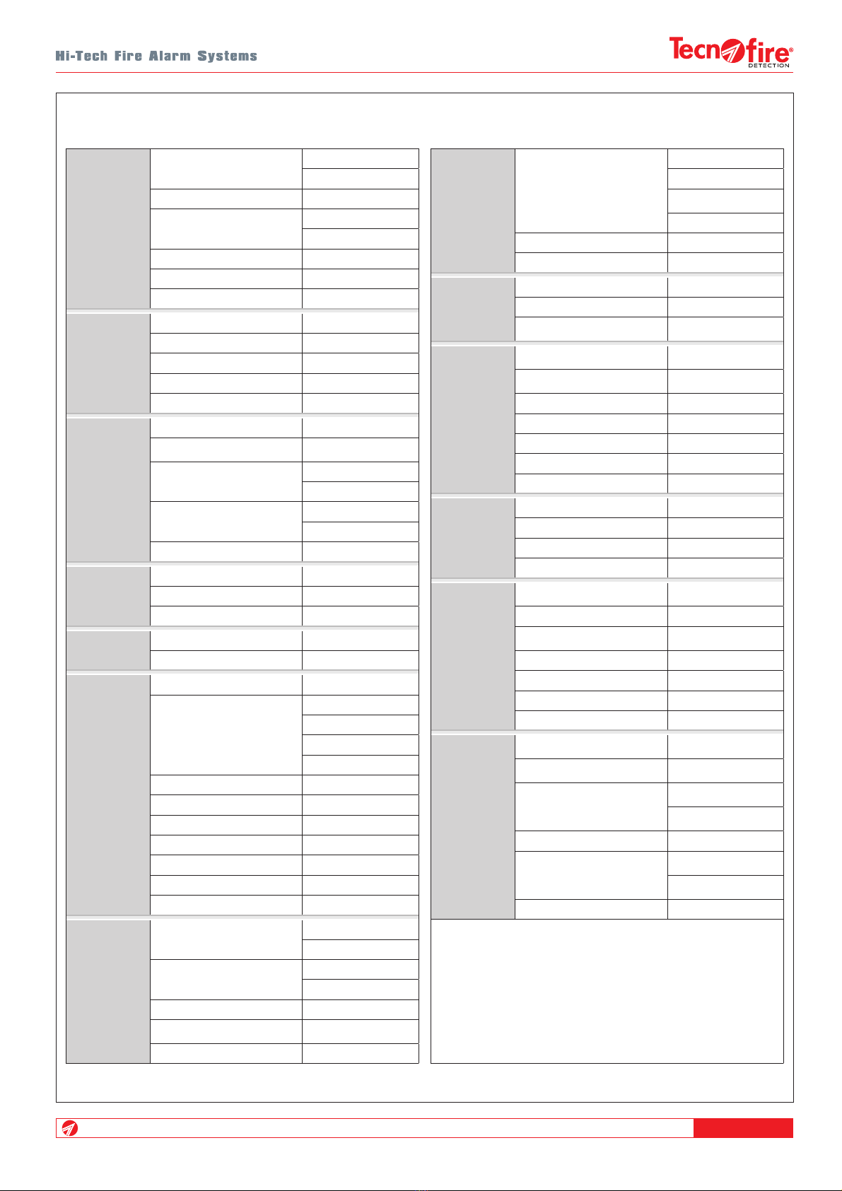
TFA2-596 • TFA4-1192 - Technical and functional specifications
Detectors
Modules
Zones
Total connectable detectors 796 (TFA4-1192)
398 (TFA2-596)
Total detectors per loop 199
Total connectable modules 396 (TFA4-1192)
198 (TFA2-596)
Total modules per loop 99
Total zones 300
Virtual zones 100
CPU
outputs
Hard-programmed relays 2
Programmable relays 3
Programmable open-collectors 3
Controlled siren output 1
Reset output 1
System
features
True color TFT display 480 x 272 pixel
Voice synthesis Customizable
vocabulary
Detection loops 4 (TFA4-1192)
2 (TFA2-596)
RS485 serial buses Master Bus (1 port)
Slave Bus (1 port)
Event buffer capacity 8192
Access
management
Access levels 4
Access codes 10
Monitored system mode ✓
Protocols Loop Fire-Speed
RS485 serial bus Fire-Bus
Ethernet hub
Type Standard 803.2
Connection channels
Local Server
Remote Server
Tecnoserver
Call back
Notification channels 8
IP addresses 16 (2 per channel)
Transmittable events 15 categories
Protocols 5 IP protocols
Encryption AES 128 bit
Transmission time SIA IP DC-09 10s
Call event queue 64 events
Automation
Formulas 400 (TFA4-1192)
200 (TFA2-596)
Alarm plans 200 (TFA4-1192)
100 (TFA2-596)
Access periods 32
Calendar Quadrennial
(programmable)
Test call with TCP/IP ✓
Expandability
Serial expansions (max. 16)
TFT-7
TFT-7S
Telephone
communicator
Ethernet interface
Network configuration 1 master + 15 slaves
Serial printer ✓
Electrical
specifications
CPU
CPU board consumption 200mA @ 24V DC
Electrical outputs I max. 50mA
Power supply voltage
(loop, serial bus, sirens) 20V…27.6V DC
Modular
power supply
Type A - switching
Fly-back
Operating voltage 230V AC +10%
-15% 50Hz
Power supply consumption 700mA AC
Rated output current 5A @ 27.6V DC
Max. current available 5A
Peak-to-peak ripple voltage ≤150mV p-p
Battery protection fuse T 1.6A
Battery
Capacity 2x 12Ah/12V
Flame class V-2 or superior
Cut-off voltage <17.6V DC
Recharge time 100% in 24h
Physical
specificatons
Environmental class 3K5
(EN 60721-3-3:1995)
Operating temperature -5°C...+40°C
Relative humidity
(without condensation) 10%...93%
Protection class IP30
Casing Aluminium - Steel
Dimensions (L x H x D) 441 x 347 x 149mm
Weight (without batteries) 6.2kg
Conformity
Fire alarm panel EN 54-2:1997 +
A1:2006
Power supply EN 54-4:1997 +
A2:2006
Certification number
0051-CPR-0388
(TFA4-1192)
0051-CPR-0389
(TFA2-596)
Year of CE marking 14
Number of declaration of
performance
002_TFA4-1192
(TFA4-1192)
003_TFA2-596
(TFA2-596)
Notified body IMQ

TFA2-596 - TFA4-1192
14

TFA2-596 - TFA4-1192 15
A E I
B F J
C G K
D H
A C
B D
29 30 31 32 33
C
13 14 15 16 17 18 19 20 21 22 23 24 25 26 27 28
OUT3 RESET
NC NC
NA NA ---
OUT4
OUT5
OUT6 -+
L1BL1A
-+
-+
SIR
-+-+ -+
34 35 36 37 38
-+
L2BL2A
-+
39 40 41 42 43
-+
L3BL3A
-+
44 45 46 47 48
-+
L4BL4A
-+
C
123456789101112
ALL
NC NA C
OUT1
NC NA C
OUT2
NC NA
C
FAULT
NC NA
49 50 51 52
-+
BA
BUS MASTER
53 54 55 56
-+
BA
BUS SLAVE
A
G G
G
G
G
G
D
K
I
J
F
H
H
B
H H C
E
D
BC
A
4-1 - Casing
4 - WARNINGS FOR INSTALLATION
CPU board 12V/12Ah batteries Speaker
Terminal board NTC probe for battery temperature monitoring USB port
ALSW285PFC power supply Mounting holes TTL port
Ground connectors Cable entry
ALARM
PREALARM
TECHNICAL ALARM
GENERAL FAILURE
PWR SPLY FAILURE
SYSTEM FAILURE
BATTERY
SIRENS STOPPED
EXCLUSION
SIREN FAIL./EXCL
IP/PSTN FAIL./EXCL..
ZONE IN TEST
SYSTEM MONITORED
MAINS PWR OK
NETWORKED DEVICES
TX CARRIED OUT
Signaling LED Function keys
Display Numeric keys
EVACUATE
RESET
ACK
MONITORED
STOP/RESET
SIR.
Control panel working
Level 2
Version: 2.0.00 ENG
Level 3 Level 4
16/02/2019 Access level 1 08:00:00
Fire control panel

TFA2-596 - TFA4-1192
16
allaRME
PREallaRME
0
23
56
89
Ok
ESC
Back
EVACUAZ.
PRESIDIATO
TACITAZ.
TAC/RIP
SIRENE
RESET
30cm
60cm
The casing of the control panel must be fixed in a position that guarantees adequate protection from accidental shocks and at
a height that grants full access to the operator. Consider the space necessary for fully opening the casing door (approx. 60cm).
Fix the casing horizontally on a solid surface using 4 dowels with 8mm diameter.
General warnings
For the safety of the operators protect the control panel, as any electronic device, against splashes and avoid placing recipients
containing liquids next to it. The control panel must be installed so as to ensure adequate ventilation. Do not cover the device with
things that may hinder correct heat dissipation.
Install the control panel at an adequate distance from heat sources (e.g. radiators) and any device that may cause electromagnetic
disturbances (e.g. radio antennas).
The cables to be used for the connections are defined by standards and installation regulations.
These are flame retardant, low smoke emission and halogen free cables.
The European standards specify the cables to be used for the construction of fire detection systems.
Among these standards we mention (non-exhaustive list):
EN 50200, EN 60228, EN 50363, EN 60332, EN 50267, IEC 60332, IEC 61034, IEC 6754.
The installer shall ascertain the current legislative requirements for his country.
For all the connections on the loop, it is recommended to use shielded multicore twisted-pair cables with flexible conductors.
For selecting the loop and 24V power supply cables to be used, refer to the below table that indicates, based on the extension of
the loop, the minimum section that must be observed.
MINIMUM CABLE SECTION
Loop extension Minimum section required Loop extension Minimum section required
750 meters 0.75mm² 1500 meters 1.5mm²
1000 meters 1mm² 3000 meters 2.5mm²
For reasons of electrical safety, the shieldings of the cables must be connected in order not to stop their path and must be
grounded inside the casing of the control panel.
The maximum length allowed for the laying of the detection loop is 3000 meters, as defined by the low voltage directive
LVD 2006/95/EU.
The maximum length allowed for the RS485 bus (Master Bus) is 1000m. For greater distances use a fiber optic connection by
connecting a TFSFC01 RS485-fiber optic converter.
The relays and the electrical outputs of the control panel and its expansion devices form a SELV voltages network (EN 60950-1).
These outputs can only be connected to circuits that comply with SELV voltages.
4-2 - Fixing of the casing
4-3 - Connection cables

TFA2-596 - TFA4-1192 17
!
!
4-4 - Compliance with EN 60950-1- Electrical Safety
Ground connection
The ground connection must comply with the valid European standards.
It is mandatory to connect the ground conductor between the casing and the door.
External circuit breaker
The power supply of the control panel is not equipped with a circuit breaker. To guarantee accordance of the installation with
the valid European standards, it is necessary to connect an external circuit breaker or a bipolar mains switch
(16A curve C, opening stroke min. 3mm) in an accessible part of the electric installation (230V AC).
The circuit breaker must be installed close to the control panel and must be clearly labeled.
Mains connection (230V AC)
The mains cable is not included. To reduce the risk of electric shocks in normal operating conditions, observe the following
precautions:
• Use a double insulated cable (with shielding) for the connection to mains power.
• The mains cable should have a diameter of minimum 3x 1.5mm2and, once it has been connected to the corresponding power
input, it should be attached with a cable tie to the casing (see figure).
• To guarantee the electrical safety and correct functioning, always connect the ground conductor between the corresponding
terminal and the threaded pin for ground connection and between the base and the door of the casing (see figure).
Connect and fasten the mains cable and the ground wire
as shown in the drawing,
The indicated connection mode ensures that,
in the event of accidental tearing of the cable,
the ground conductor will be the last to be detached.

TFA2-596 - TFA4-1192
18
29 30 31 32 33
0
21 22 23 24 25 26 27 28
--
T
4
OUT5
OUT6 -+
L1BL1A
-+
-+
SIR
-+-+
34 35 36 37 38
-+
L2BL2A
-+
39 40 41 42 43
-+
L3BL3A
-+
44 45 46 47 48
-+
L4BL4A
-+
49 50 51 52
-+
BA
BUS MASTER
Battery information
The batteries must always be two. Never use batteries of different
manufacturers and capacities. Capacities lower than 12Ah,
besides reducing the autonomy, distort its resistance values
causing possible improper failure signaling.
In accordance with the standards EN 54, it is mandatory to block
the two batteries using the provided fixing bracket.
The bracket must be screwed on the casing.
Self-regulation of the charging voltage
The power supply reads the temperature of the battery via the
NTC (Negative Temperature Coefficient) probe and adjusts the
charging voltage of the batteries according to the themperature
measured. The NTC probe must be connected to the dedicated
polarized connector, the sensing end of the probe should be
attached to the battery casing using an electrical tape.
Automatic disconnection
In the absence of the primary power supply voltage
(230V AC mains), the batteries automatically assume the power
supply of the system. When the battery voltage drops to a value
<18V for a duration of 15 minutes, the batteries automatically
disconnect, to prevent their deep discharge and consequent
functional degradation.
Battery bracket fastening
Insert the bracket into the two slots located at the bottom.
Rotate the bracket blocking the batteries and fasten
the bracket using the supplied screws.
4-5 - Secondary power supply

TFA2-596 - TFA4-1192 19
OK
1
4
7
2
5
8
0
6
9
3
ESC
ESC
BACK
BACK
5 - USER INTERFACE
The user interface of the control panel consists of a 480 x 272 pixels TFT color graphic display, 16 notification LED, 5 function
keys, 7 navigation keys and 10 number keys, with which the user can manage the system. The user interface is completed by
the speaker that, according to the functional states of the control panel, provides audible alarms or notifications by using the voice
synthesis function.
The control panel manages 10 access codes associated to 4 levels of access: level 1 (not protected by code), level 2 (user),
level 3 (installation and maintenance personnel) and level 4 (manufacturer).
Level 1
In stand-by, the control panel provides access to the functions reserved to the level 1, without having to enter a code.
The access level 1 allows to perform the following operations:
A - Access the upper levels with the keys 1 or 2 or 3 and the relevant code (password)
B - Acknowledge the alarm pressing the ACK key
C-Display the acknowledged, the ongoing alarms and those stored in the event categories folders.
Level 2
To access level 2 press the key 1 and enter the relevant user code, then press the confirmation key.
At level 2, it is possible to perform all the operations of the level 1, plus the followings:
A - Reset the control panel pressing the RESET key.
B-Switch the operating state of the control panel (monitored/not monitored).
C-Manually activate an evacuation alarm.
D - Access the list of menus reserved to level 2.
E - Stop and reset the sirens.
Level 3
To access level 3 press the key 2 and enter the relevant installer code, then press the confirmation key.
Access to level 3 is reserved to staff authorized to edit important operating parameters.
At level 3 it is possible to perform all the operations of the levels 1 and 2 and to access the menus reserved to level 3
(system configuration menu)
Level 4
To access level 4 close the JP6 KEY jumper, press the key 3 and enter the manufacturer code, then press the confirmation key.
Access to level 4 is reserved to highly qualified personnel authorised by the manufacturer to carry out technical services of special
importance.
At level 4 it is possible to perform all the operations of the previous levels and to access the menus reserved to level 4.
The following table shows how to enter the codes and access the different access levels:
Access level key + Code + Confirmation key.
5-1 - Control panel
5-2 - Access levels and codes
ALARM
PREALARM
TECHNICAL ALARM
GENERAL FAILURE
PWR SPLY FAILURE
SYSTEM FAILURE
BATTERY
SIRENS STOPPED
EXCLUSION
SIREN FAIL./EXCL
IP/PSTN FAIL./EXCL..
ZONE IN TEST
SYSTEM MONITORED
MAINS PWR OK
NETWORKED DEVICES
TX CARRIED OUT
Control panel working
Level 2
Release: 2.0.00 ENG
Level 3 Level 4
16/02/2019 Access level 1 08:00:00
Fire control panel
RESET
EVACUATE
ACK
MONITORED
STOP/RESET
SIRENS

TFA2-596 - TFA4-1192
20
21 3
1
+
1 1 1 1 1
+
1
2
+
1 2 3 4 5
+
1
3
+
5 4 2 3 1
+
1
ACCESS TO ACCESS LEVELS
Access level 1 is not protected by code
Access level 2
Access level 3
Access level 4
16/02/2019 08:00:00Access level 1
Level 2 Level 3 Level 4
Release: 2.0.00 ENG
Control panel working
Fire control panel
The table describes the keys on the front panel of the control panel.
5-3 - Function keys
Key Description Operational sequence
RESET
Reset (deletion) of all prealarm, fire alarm, technical prealarm,
technical alarm and failure notifications and reset of the control
panel to normal operating condition.
1 - Press RESET
2 - Enter level 2 code
The LED and display notifications are cleared.
EVACUATE
Activation of the programmed procedure for the evacuation alarm,
activation of the sirens and output modules programmed to be
activated by the evacuation alarm procedure.
1 - Press EVACUATE
2 - Enter level 2 code
3 - Confirm the operation
The ALARM LED turns on. The display shows Evacuation.
ACK
Acknowledges the alarms issued for prealarm, fire alarm, technical
prealarm, technical alarm and failure. Moreover, the local speakers of
all the control panels and repeaters are muted.
N.B. The button does not mute the sirens and does not stop the
external activation devices (output modules, sirens etc.).
1 - Press ACK
The code is not required.
The ALARM LED remains lit.
The display alarm notifications remain visible.
MONITORED Toggle of the Monitored system mode.
N.B. This function only works if the option has been programmed.
1 - Press MONITORED
2 - Enter level 2 code
The MONITORED SYSTEM LED turns on or off:
LED on = monitored, LED off = not monitored
stop/RESET
SIRENS
Stop and reset of all sirens programmed for prealarm, fire alarm,
technical prealarm, technical alarm and failure as well as all
external actuating devices (output modules, sirens etc.) if the
acknowledgment function has been programmed for each of them.
1 - Press STOP/RESET SIRENS
2 - Enter level 2 code
The SIRENS STOPPED LED turns on.
OK
Navigation and confirmation keys. The arrow keys allow navigation
of the menus. Depending on the context, you can change the
displayed page and/or increase and decrease programming
parameters. The OK key is to confirm the selection.
Move the cursor up - Increase the value
Move the cursor down - Decrease the value
Move the cursor left - Decrease the value
Move the cursor right - Increase the value
OK Confirm the selection
ESC
ESC The ESC key allows to exit from the menu or displayed function.
BACK
BACK The BACK key allows to move the cursor to the previous position
and erase its contents
19
...........
The number keys allow to enter the code and select the menus and
devices in a direct way.
21 3
Number keys 1, 2 and 3 are accompanied by an arrows up symbol.
Depending on the context, they are numeric keys or pointing keys.
The arrows indicate the pointing boxes displayed directly above
them: access to level 2, 3 and 4.
This manual suits for next models
3
Table of contents
Other Tecnoalarm Fire Alarm manuals

Popular Fire Alarm manuals by other brands


Notifier
Notifier ID50 SERIES Installation, comissioning & configuration manual
Edwards Signaling & Security Systems
Edwards Signaling & Security Systems AdaptaBeacon 116DEXSTC-FJ installation instructions

Simplex
Simplex Saturn 2500 operating instructions

Simplex
Simplex SafeLINC 4100 operating instructions

Zeta Alarm Systems
Zeta Alarm Systems INFINITY ID2 installation manual

Fire-Lite Alarms
Fire-Lite Alarms MS-2 instructions


