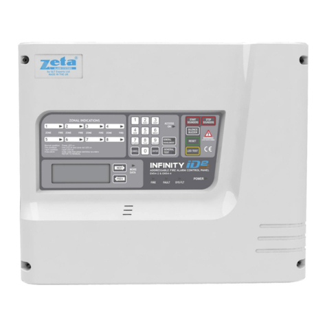
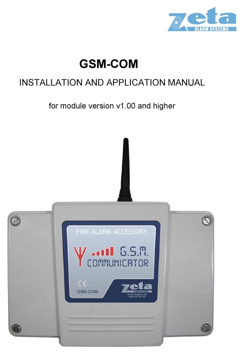
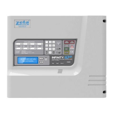
Zeta ID2/4 User manual

INFINITY ID2 INSTALLATION MANUAL.
Software Versions: PANEL 1.N & LOOP O.N
A roved Document No: GLT-211-7-1
Issue 1.9 Author: MG/NJ Date: 06/04/2016 PAGE 1
CONTENTS
1. SAFETY INFORMATION ...................................................................................................................................... 3
1.1 Installation Information .............................................................................................................................. 3
1.2 Safety Precautions uring Normal Operation of Panel .............................................................................. 3
1.3 Battery Information .................................................................................................................................... 3
1.4 Pro uct Disposal at the en of its working life ........................................................................................... 3
2. PRODUCT DESIGN INFORMATION ..................................................................................................................... 4
2.1 Fire Alarm Control Section ......................................................................................................................... 4
2.2 Power Supply Section ................................................................................................................................. 4
2.3 Environmental ............................................................................................................................................ 4
3.0 Panel escription & esign concept ........................................................................................................... 5
4 USING THIS MANUAL ......................................................................................................................................... 6
4.1 Equipment guarantee ................................................................................................................................. 6
5 DESIGNING A SYSTEM ........................................................................................................................................ 7
5.1 Designing a ID2 System .............................................................................................................................. 7
6. INSTALLING THE SYSTEM................................................................................................................................... 8
6.1 Consi erations before Installation ............................................................................................................. 8
6.1.1 MOUNTING THE CONTROL PANEL ...................................................................................................... 8
6.1.2 RECOMMENDED CABLE TYPES AND THEIR LIMITATIONS ................................................................... 8
6.1.3 MAINS WIRING RECOMMENDATIONS ................................................................................................ 8
6.2 First Fix ....................................................................................................................................................... 9
6.2.1 MOUNTING THE FIRE ALARM PANEL .................................................................................................. 9
6.2.2 FIXING THE BACK BOX TO THE WALL .................................................................................................. 9
6.2.3 PLANNING CABLE ENTRY .................................................................................................................... 9
6.2.4 CONNECTING THE MAINS POWER .................................................................................................... 10
6.2.5 CONNECTING THE BATTERIES ........................................................................................................... 11
7. ZONE WIRING .................................................................................................................................................. 12
7.1 Specific evice wiring instructions ........................................................................................................... 13
7.1.1 CP3/AD Manual Call Point ..................................................................................................................... 13
........................................................................................................................................................................ 13
7.1.2 MKII etectors (All types) Base connection........................................................................................... 13
7.1.3 ZAI - MI Input Mo ule ........................................................................................................................... 14
7.1.4 ZAIO – MI Input/output Mo ule ........................................................................................................... 14
7.1.5 ZASC – MI Soun er Control Mo ule ...................................................................................................... 15
7.1.6 ZAZM – MI Conventional Zone Mo ule ................................................................................................. 15
7.1.7 Xtratone Soun er/Soun er Flasher ....................................................................................................... 16
7.1.8 San wich Soun er ................................................................................................................................. 16
7.1.9 A ressable Remote LED In icator ....................................................................................................... 17
7.2 Setting the evice zone & ID ( etectors, call points & soun ers) ............................................................ 18
7.3 LOOP MODE - MAXIMUM LOOP LENGTH RECOMMENDATIONS ............................................................. 20
8 SOUNDERS ........................................................................................................................................................ 21
9. AUXILIARY OUTPUTS ....................................................................................................................................... 21
9.1 Auxiliary output wiring ............................................................................................................................. 21
10. FIELD DEVICE TERMINATION ......................................................................................................................... 22
10.1 Terminating the wiring ........................................................................................................................... 22
11 OTHER CONNECTIONS .................................................................................................................................... 22
11.1 Repeater connection .............................................................................................................................. 23
12. CONFIGURING THE ID2 FIRE ALARM PANEL .................................................................................................. 24
12.1 CONFIGURING THE ZONES ..................................................................................................................... 24
12.1.1 FROM A BLANK INFINITY ID2 PANEL ............................................................................................... 24
12.1.2 FROM A PREVIOUSLY CONFIGURED PANEL .................................................................................... 24
12.2 Verifying the Zone configuration ............................................................................................................ 24
12.3 Labelling the Panel an Zones ................................................................................................................ 25
12.4 Labelling the Devices .............................................................................................................................. 25
12.5 Setting time an ate ............................................................................................................................. 25
12.6 Changing the alarm Tones - soun ers .................................................................................................... 25
12.7 CHANGING FIRE RELAY RESPONSE .................................................................................................... 25
12.8 CHANGING INPUT/OUTPUT INTERFACE RESPONSE .......................................................................... 25
www.acornfiresecurity.com

INFINITY ID2 INSTALLATION MANUAL.
Software Versions: PANEL 1.N & LOOP O.N
A roved Document No: GLT-211-7-1
Issue 1.9 Author: MG/NJ Date: 06/04/2016 PAGE 2
12.8.1 DEFAULT SETTING ........................................................................................................................... 25
12.8.2 SETTING INDIVIDUAL I/O UNIT OPERATION - RELAY ........................................................................... 26
12.8.3 SETTING INDIVIDUAL I/O UNIT OPERATION - INPUT ...................................................................... 26
12.8.4 I/O UNIT OPERATION - PANEL LINK ................................................................................................ 26
12.8.5 CONFIGURING ALARM OUTPUT RESOUND OPERATION ................................................................ 27
12.9 Setting the LCD language........................................................................................................................ 27
12.10 Software Versions ................................................................................................................................ 27
13 ALARM VERIFICATION .................................................................................................................................... 28
13.1 Alarm Verification Options ..................................................................................................................... 28
13.1 How Alarm Verification Works ............................................................................................................... 28
13.2 Setting the Alarm Verification Delay ...................................................................................................... 28
13.3 Applying Alarm Verification Delay to a etector .................................................................................... 28
14 RESTORING THE PANELS DEFAULT SETTINGS ................................................................................................ 29
15 VIEWING PANEL INFORMATION .................................................................................................................... 30
15.1 Menu Structure ...................................................................................................................................... 30
15.2 Viewing evice status ............................................................................................................................. 31
15.3 Locating a evice .................................................................................................................................... 31
15.4 Using the event log ................................................................................................................................. 32
16. THE FIRE ALARM CONDITION ........................................................................................................................ 33
16.1 Viewing a fire alarm event ..................................................................................................................... 33
16.2 Viewing Faults uring a fire alarm con ition .......................................................................................... 33
16.3 Viewing Zone Disablements uring a fire alarm con ition .................................................................... 33
16.4 Viewing Device Disablements uring a fire alarm con ition .................................................................. 33
16.5 Viewing Zones in Test Mo e uring a fire alarm con ition .................................................................... 33
17. DISABLEMENT ............................................................................................................................................... 34
17.1 Zone isablement ................................................................................................................................... 34
17.2 To programme zone (or soun ers) as isable ...................................................................................... 34
17.3 Device isablement ................................................................................................................................ 35
17.4 Viewing isablements ............................................................................................................................ 35
17.4.1 VIEWING DISABLED ZONES ............................................................................................................. 35
17.4.2 VIEWING DISABLED DEVICES .......................................................................................................... 35
18. TEST MODE .................................................................................................................................................... 36
18.1 Why use test mo e................................................................................................................................. 36
18.2 To programme zone in test mo e .......................................................................................................... 36
18.3 To program soun er circuits in test mo e ............................................................................................. 36
19. GENERAL FAULT FINDING ............................................................................................................................. 37
19.1 Common fault ......................................................................................................................................... 37
19.2 Zone contents fault fin ing .................................................................................................................... 37
19.3 Zone faults .............................................................................................................................................. 37
19.4 Supply faults ........................................................................................................................................... 38
19.5 Earth faults ............................................................................................................................................. 38
19.6 Double a ress ....................................................................................................................................... 38
19.7 System fault ............................................................................................................................................ 39
20.1 Stan by battery calculation.................................................................................................................... 40
20.2 Device Values for Battery calculation ..................................................................................................... 40
20.3 Example battery calculation ................................................................................................................... 41
21. PCB TERMINATION CONNECTIONS. .............................................................................................................. 42
22 SPECIFICATIONS ......................................................................................................................................... 43
22.1 Enclosure specifications ......................................................................................................................... 43
22.2 Electrical specifications ......................................................................................................................... 43
www.acornfiresecurity.com

INFINITY ID2 INSTALLATION MANUAL.
Software Versions: PANEL 1.N & LOOP O.N
A roved Document No: GLT-211-7-1
Issue 1.9 Author: MG/NJ Date: 06/04/2016 PAGE 3
1. SAFETY INFORMATION
WARNING: Read this section completely before commencing installation.
1.1 Installation Information
THIS FIRE ALARM CONTROL PANEL IS CLASS 1 E UIPMENT AND MUST BE EARTHED
This equipment must be installed and maintained by a qualified and technically expe ienced pe son.
This C.I.E.must be wi ed to a fused spu ated at 3A. It must NOT be connected via a emovable plug, o be
connected th ough an RCD device.
P io to commencing installation of the cont ol panel, ensu e that adequate p ecautions a e taken to p event
damage to the sensitive elect onic components on the display boa d and the cont ol boa d due to elect ostatic
discha ge. You should discha ge any static elect icity you may have accumulated by touching a convenient
ea thed object such as an unpainted coppe adiato pipe. You should epeat the p ocess at egula inte vals
du ing the installation p ocess, especially if you a e equi ed to walk ove ca pets.
The panel must be located in a clean, dry position, which is not subject to excessive shock or vibration
and at least 2 meters away from pager systems or any other radio transmitting equipment. The operating
temperature range is ºC to 4 ºC; maximum humidity is 95%.
HANDLING THE PCB
If the PCB is to be removed to ease fitting the enclosure and cables, care must be taken to avoid damage
by static.
The best method is to wea an ea th st ap, but touching any ea th point (eg building plumbing) will help to
discha ge any static. Always hold the PCB by its sides and avoid touching the legs of any components. Keep the
PCB away f om damp di ty a eas, e.g. in a small ca dboa d box.
1.2 Safety Precautions during Normal Operation of Panel
NOTE: When the ID2 panel is operating normally, i.e. not being tended by service personnel, the front
cover should be screwed closed with the hex screws provided.
1.3 Battery Information
This C.I.E. uses 2 x 12V Sealed Lead Acid (SLA) batte ies up to 7 Ah.
CAUTION:
RISK OF EXPLOSION IF BATTERY IS REPLACED BY AN INCORRECT TYPE.
DISPOSE OF USED BATTERIES ACCORDING TO BATTERY MANUFACTURERS INSTRUCTIONS
IMPORTANT NOTES ON BATTERIES:
DANGER: Batte ies a e elect ically live at all times. NEVER short circuit the battery terminals.
WARNING: Batte ies a e often heavy; take g eat ca e when lifting and t anspo ting batte ies. Fo weights above
24 kilos, lifting aids should be used.
DANGER: Do NOT attempt to emove the batte y lid o tampe with the inte nal wo kings of the batte y.
Elect olyte is a highly co osive substance, and p esents significant dange to you self and to anything else it
touches. In case of accidental skin o eye contact, flush the affected a ea with plenty of clean, f esh wate and
seek immediate medical attention.
Valve Regulated Lead Acid (VRLA) batte ies a e “low maintenance”, equi ing no elect olyte top-up o
measu ement of specific g avity.
1.4 Product Disposal at the end of its working life
Like all elect onic equipment, at the end of its wo king life this unit should not be disposed of in
a efuse bin. It should be taken to a local ep ocessing site as pe the guidelines of the WEEE
di ective, fo co ect disposal.
www.acornfiresecurity.com
INFINITY ID2 INSTALLATION MANUAL.
Software Versions: PANEL 1.N & LOOP O.N
A roved Document No: GLT-211-7-1
Issue 1.9 Author: MG/NJ Date: 06/04/2016 PAGE 4
2. PRODUCT DESIGN INFORMATION
2.1 Fire Alarm Control Section
The ID2 Fi e Ala m Cont ol and Indicating Equipment (CIE) has been designed to
EN 54-2:1997 +A1 - Fi e
Detection & Fi e Ala m Systems – Cont ol & Indicating Equipment
As well as meeting the equi ements of EN 54-2:1997 +A1, the Infinity ID2 also has the following
options with equi ements:-
Clause 7.8 Output to fi e ala m devices (Option with equi ements)
Clause 7.12 Dependencies on mo e than one ala m signal (Option with equi ements)
Clause 8.3 Fault signals f om points (Option with equi ements)
Clause 9.5 Disablement of add essable points (Option with equi ements)
Clause 10 Test Condition (Option with equi ements)
The ID2 also has the following ancilla y functions not equi ed by the Standa d:-
• Se ial epeate output (RS485)
2.2 Power Supply Section
The ID2 Fi e Ala m Panels Powe Supply Equipment (PSE) has been designed to
EN 54-4:1997 A1+A2 - Fi e
Detection & Fi e Ala m Systems –
Powe Supply Equipment.
The PSE has been designed to cha ge batte ies up to 7Ah within the time limits specified by EN54-4.
The PSE will d aw a maximum of 25mA f om the batte y in the event of mains failu e.
The PSE is a switching powe supply, with a supply ating (IMAX) of 2.0 Amps
The PSE has a 350mA limited cha ge output
2.3 Environmental
• It will ope ate in ambient tempe atu es of –5 to 40oC
• It will ope ate in a elative humidity of up to 95% (non condensing)
• It will withstand vib ations between 5 & 150 Hz
• The CIE & PSE should be maintained as desc ibed in section 3 of the Use Manual, Maintenance Guide &
Log Book.
www.acornfiresecurity.com

INFINITY ID2 INSTALLATION MANUAL.
Software Versions: PANEL 1.N & LOOP O.N
A roved Document No: GLT-211-7-1
Issue 1.9 Author: MG/NJ Date: 06/04/2016 PAGE 5
3.0 Panel description & design concept
The ID2 is an eight zone intelligent fi e ala m cont ol panel designed to EN54 pa t 2 & 4.
The ID2 has been designed to use zone powe ed sounde s but also has 2 conventional sounde ci cuits. All
sounde s on a ID2 panel will activate on any ala m.
It has been designed to give the advantages of an add essable system, with the simplicity of a conventional
system. To help achieve this, the ID2 uses default values to cut out many of the p og amming steps no mally
associated with add essable panels.
This leaves only the device label to be ente ed by the installe . This is done with the built in keyboa d
www.acornfiresecurity.com

INFINITY ID2 INSTALLATION MANUAL.
Software Versions: PANEL 1.N & LOOP O.N
A roved Document No: GLT-211-7-1
Issue 1.9 Author: MG/NJ Date: 06/04/2016 PAGE 6
4 USING THIS MANUAL
It is beyond the scope of this manual to teach the use all the int icacies of fi e ala m system design. If in doubt
about what is equi ed, ead BS 5839: Pt 1: 2013 “Fi e Detection and Ala m Systems fo buildings (UK Code of
P actice fo System Design, Installation, commissioning and maintenance)” available f om the BSI, o at you
local efe ence lib a y. Othe national egulations will also give simila guidance.
This manual explains, in a step-by-step manne , the p ocedu e fo the basic design and installation of the ID2
ange of Fi e Ala m Cont ol Panels.
It gives detailed inst uctions on how to use all the featu es on this fi e ala m panel.
Fo ope ational and maintenance info mation, please efe to document USER MANUAL, MAINTENANCE
GUIDE & LOG BOOK. It also contains a System set-up table, and Installation Ce tificate, that must be
completed by the Commissioning Enginee p io to system handove .
Unlike the User Manual, this Installation Manual must not be left accessible to the User.
4.1 Equipment guarantee
If this equipment is not fitted and commissioned acco ding to ou guidelines, and the elevant National
Standa ds, by an app oved and competent pe son o o ganisation, the wa antee may become void.
www.acornfiresecurity.com

INFINITY ID2 INSTALLATION MANUAL.
Software Versions: PANEL 1.N & LOOP O.N
A roved Document No: GLT-211-7-1
Issue 1.9 Author: MG/NJ Date: 06/04/2016 PAGE 7
5 DESIGNING A SYSTEM
This manual is not designed to teach Fi e Ala m System design. It is assumed that the System has been
designed by a competent pe son, and that the installe has an unde standing of Fi e Ala m System components
and thei use.
We st ongly ecommend consultation with a suitably qualified, competent pe son ega ding the design of the Fi e
Ala m System. The System must be commissioned and se viced in acco dance with ou inst uctions and the
elevant National Standa ds. Contact the Fi e Office conce ned with the p ope ty at an ea ly stage in case he
has any special equi ements. If in doubt, ead BS 5839: Pt 1: 2013 “Fi e Detection and Ala m Systems fo
buildings (Code of P actice fo System Design, Installation, commissioning and maintenance)” available f om the
BSI, o at you local efe ence lib a y.
5.1 Designing a ID2 System
Designing a ID2 System is a fai ly st aight fo wa d matte . It just takes a bit of thought to zone allocation du ing
the system design stage.
1. Decide on the zone allocation fo the system. Each default zone can have a maximum of 15 devices fitted.
Conside the simplified 3-sto ey building below.
The advantage of this method of zone allocation is that it simplifies the panel setup by eliminating a
p og amming stage.
2. Sounde ope ation. On the ID2 Panels, it is a common sounde s, i.e. an ala m signal f om any device will
activate all sounde s.
If mo e sophisticated sounde & I/O ope ation is needed, ask you deale about the P emie Quat o panel.
3. Wheneve possible, give each device as desc iptive a label as possible. The bette the desc iption, the easie
it is to locate in the event of an ala m. The panel allows 20 cha acte s fo the device ID, and 16 cha acte s fo
the zone labels. It may be necessa y to use abb eviations to achieve the equi ed label.
4. Keep the design of the system, and any changes to it well documented. This makes it easie to t ace any
configu ation e o s du ing installation & commissioning.
Zone 1 = ID 1-15
Zone 2 = ID 1-15
Zone 3 = ID 1-15
Zone 4 = ID 1-15
Zone 5 = ID 1-15
Zone 6 = ID 1-15
Zone 7 = ID 1-15
Zone 8 = ID 1-14
Z
O
N
E
7
ZONE 5
ZONE 6
ZONE 1
ZONE 2
ZONE 3
ZONE 4
www.acornfiresecurity.com

INFINITY ID2 INSTALLATION MANUAL.
Software Versions: PANEL 1.N & LOOP O.N
A roved Document No: GLT-211-7-1
Issue 1.9 Author: MG/NJ Date: 06/04/2016 PAGE 8
6. INSTALLING THE SYSTEM
6.1 Considerations before Installation
6.1.1 MOUNTING THE CONTROL PANEL
The cont ol panel should be installed in acco dance with the following ecommendations:-
• The panel should be close to the main ent ance of the building, so that it can be viewed by any fi e-
fighting pe sonnel ente ing the building.
• It should be fitted to a stu dy wall that will not flex unnecessa ily.
• It should be mounted at eye level, in o de fo it to be viewed without need of a ladde .
• It should be installed in a d y, weathe p oof place, p efe ably NOT in di ect sunlight.
• It should be easily accessible, so that the esponsible pe son can pe fo m thei egula fi e ala m
checks.
6.1.2 RECOMMENDED CABLE TYPES AND THEIR LIMITATIONS
All wiring must be installed to meet BS5839: Pt1: 2013 and BS 7671 (Wiring Regs) standards. Other
National standards of fire alarm system installation should be adhered to where applicable.
Sc eened cables should be used th oughout the installation to help shield the Panel f om outside inte fe ence
and ensu e EMC compatibility.
The two catego ies of cable acco ding to BS5839: Pt1: 2013, Clause 26 “Fi e Detection and Ala m Systems fo
Buildings (Code of P actice fo System Design, Installation and Se vicing)” a e:
Standard fire resisting cable – to PH30 classification of EN 50200
Enhanced fire resisting cable – to PH120 classification of EN 50200
(Note that all cables should be at least 1mm2 cross section
On the ID2 the gene al ecommendation would be to use standa d fi e esistant cable, such as Fi etuff , FP200
o any equivalent. These cables a e sc eened, and will p ovide good EMC shielding when p ope ly g ounded at
the panel. Ce tain system specifications may demand the use of a pa ticula type of cable and due ega d
should be paid to this fact.
Depending on the envi onment, the cables may need mechanical p otection (such as a conduit).
6.1.3 MAINS WIRING RECOMMENDATIONS
The Mains supply to the FACP is fixed wi ing, using Fire resisting 3-co e cable (Between 1 mm² and 2.5mm²) o
a suitable 3-conducto system, fed f om an isolating double pole switch fused spu , fused at 3A. IT SHOULD
NOT BE CONNECTED THROUGH AN RCD. This should be secu e f om unautho ised ope ation and be
ma ked ‘FIRE ALARM: DO NOT SWITCH OFF’. The supply must be exclusive to the Fi e Panel. MAKE SURE
ANY SPARE ENTRY HOLES ARE COVERED
Fo info mation on how to connect Mains to the Panel’s Powe Supply PCB, see page 11.
Also efe to ating info mation on the mains cove inside the FACP.
www.acornfiresecurity.com

INFINITY ID2 INSTALLATION MANUAL.
Software Versions: PANEL 1.N & LOOP O.N
A roved Document No: GLT-211-7-1
Issue 1.9 Author: MG/NJ Date: 06/04/2016 PAGE 9
6.2 First Fix
6.2.1 MOUNTING THE FIRE ALARM PANEL
The ID2 comes with many cable ent y holes. If anothe ent y hole is equi ed, it is st ongly ecommended that
the, the te mination PCBs should be emoved and sto ed in a safe place. This would also help while fixing the
back box to the wall.
6.2.2 FIXING THE BACK BOX TO THE WALL
Figure 2: Plan view inside the enclosure without PCBs. Side view for surface installation.
Note that the enclosure has a document tray on the left hand side that holds the panel manuals. If semi
flushing or fitting to a tight space, remember to remove the manuals before fitting to the wall.
Fix the enclosu e to the wall using the th ee mounting holes p ovided.
Check the build & condition of the wall to decide a suitable sc ew fixing.
The mounting holes a e designed fo No 8 oundhead o counte sunk woodsc ews (o simila ).
Remove any deb is f om the enclosu e.
Take ca e not to damage the FACP du ing installation.
6.2.3 PLANNING CABLE ENTRY
Fig.2 above shows the location of the cable ent ies to facilitate planning of wi ing (home uns) to be b ought to
the panel.
The 230Va.c. Mains cable must be fed into the enclosu e via one of the cable ent ies at the top ight co ne of
the back box. (Refe to “Connecting the Mains” on Following Page).
www.acornfiresecurity.com

INFINITY ID2 INSTALLATION MANUAL.
Software Versions: PANEL 1.N & LOOP O.N
A roved Document No: GLT-211-7-1
Issue 1.9 Author: MG/NJ Date: 06/04/2016 PAGE 10
6.2.4 CONNECTING THE MAINS POWER
Figure 3: Power Supply PCB layout and Mains connection details
The panel should be connected to 220-240V AC by a 3A ated spu to the fuse box with 1mm
2
to 2.5mm
2
3-co e cable. Nothing else should be connected to this supply. The cable should be
fi e esistant.
Having ente ed the panel via the cable gland, the mains cable should be passed twice th ough
the p ovided fe ite. This is made easie by emoving the oute insulation. The cable is then
connected to the Live, Ea th and Neut al connections ma ked on the powe supply cage. The
Mains is p otected by an INTERNAL fuse on the PSU cage. (This fuse is not use eplaceable)
The incoming mains cable should be kept sepa ate f om the zone cables to help minimise
mains inte fe ence.
It is advisable to apply powe to the panel befo e connecting any devices, to check fo co ect
ope ation, and to familia ise you self with the fi e ala m panels cont ols.
www.acornfiresecurity.com

INFINITY ID2 INSTALLATION MANUAL.
Software Versions: PANEL 1.N & LOOP O.N
A roved Document No: GLT-211-7-1
Issue 1.9 Author: MG/NJ Date: 06/04/2016 PAGE 11
6.2.5 CONNECTING THE BATTERIES
Figure 4: Battery location and connection details
Although the e a e many sizes of suitable batte y, the sizes we usually ecommend
fo the ID2 a e 12V 7Ah,
To calculate the exact equi ement, use the equation in section 20.1, STANDBY
BATTERY CALCULATIONS
The two batte ies a e wi ed in series to give 24 Volts.
Connect the –ve of Batte y 1 to the black batte y cha ge lead.
Connect the +ve of Batte y 2 to the red batte y cha ge lead.
The +ve of the fi st batte y is connected to the -ve of the second batte y using the
FUSED link wi e supplied.
When fitting the batteries, take care not to damage the temperature monitoring
thermistor. (Next to the cha ge lead connections).This is used to p event
ove cha ging the batte ies in high ambient tempe atu es.
Recommended Batteries
Powe sonic PS-1270, 12V, 7Ah (o equivalent)
www.acornfiresecurity.com

INFINITY ID2 INSTALLATION MANUAL.
Software Versions: PANEL 1.N & LOOP O.N
A roved Document No: GLT-211-7-1
Issue 1.9 Author: MG/NJ Date: 06/04/2016 PAGE 12
7. ZONE WIRING
The ID2 can be wi ed with up to 8 sepa ate adial ci cuits each with 15 devices pe ci cuit. It may also be wi ed as a single loop.
When Wi ed as a Loop, Zone 1 is used as Loop OUT (Side A), and Zone 2 is used as Loop IN (Side B)
Each te mination is identified on the te minal labels. The Ea thing of the cable sc eens should be as shown below.
www.acornfiresecurity.com

INFINITY ID2 INSTALLATION MANUAL.
Software Versions: PANEL 1.N & LOOP O.N
A roved Document No: GLT-211-7-1
Issue 1.9 Author: MG/NJ Date: 06/04/2016 PAGE 13
7.1 Specific device wiring instructions
All p oducts will come with thei own wi ing inst uctions. This should be used when connecting a p oduct. But as a gene al
guideline, he e a e the connection details of most Zeta Add essable p oducts.
7.1.1 CP3/AD Manual Call Point
The CP3/AD call point has a built in isolator which can be wire in circuit or not use . This is one by means of not
wiring to the negative out terminal on the call point. The following terminals are use for connecting the call
point.
2 x Negative in terminals (note if you only connect to the negative in terminals then the isolator is bypasse )
1 x Positive in terminal
1 x Positive out terminal
1 x Negative out terminal (note if use puts the isolator in circuit)
1 x Earth terminal use to connect the cable screen
7.1.2 MKII detectors (All types) Base connection
Negative out
te minal used
when isolato is
equi ed
P otocol setting
jumpe link must
be emoved fo
MKII p otocol
The connection for the etectors
bases is ma e as follows:
Terminal L1IN is –ve (Blue)
Terminal L2 is +ve (Brown)
These are the only two
connections require .
www.acornfiresecurity.com

INFINITY ID2 INSTALLATION MANUAL.
Software Versions: PANEL 1.N & LOOP O.N
A roved Document No: GLT-211-7-1
Issue 1.9 Author: MG/NJ Date: 06/04/2016 PAGE 14
Deep Base MKII-CB/D Common Base MKII-CB
7.1.3 ZAI - MI Input Module
The end of line esisto value is 20KΩ and the t igge esisto value is 1 KΩ.
7.1.4 ZAIO – MI Input/output Module
The end of line esisto value is 20KΩ and the t igge esisto value is 1K
www.acornfiresecurity.com

INFINITY ID2 INSTALLATION MANUAL.
Software Versions: PANEL 1.N & LOOP O.N
A roved Document No: GLT-211-7-1
Issue 1.9 Author: MG/NJ Date: 06/04/2016 PAGE 15
7.1.5 ZASC – MI Sounder Control Module
The ZASC requires an external 24v c power supply (as shown in the above iagram). The EOL for the soun er
circuit is 10KΩ. When using the ZASC make sure the PSU being use has a fault output relay, so that in the event
of a power supply fault it is reporte to the control panel.
Note: All Power Supplies used on fire alarm systems MUST comply with EN54 part 4
7.1.6 ZAZM – MI Conventional Zone Module
The ZAZM powers the conventional zone from the a ressable systems loop, so no external power supply is
require . The EOL for the zone is 6.2KΩ.
www.acornfiresecurity.com

INFINITY ID2 INSTALLATION MANUAL.
Software Versions: PANEL 1.N & LOOP O.N
A roved Document No: GLT-211-7-1
Issue 1.9 Author: MG/NJ Date: 06/04/2016 PAGE 16
7.1.7 Xtratone Sounder/Sounder Flasher
The Xtratone soun er or soun er flasher is a wall mount soun er. The programming of the soun er is one via
the D.I.L switch mounte on the insi e (front). It may also be programme via the han hel programming tool.
Connecting the soun er is one using the terminals in the back box of the evice. Please refer to the above
iagram.
7.1.8 Sandwich Sounder
The san wich soun er has no wiring to connect as it just clips straight on to a stan ar base. It will run as a
platform soun er using no a ress, it is controlle by the etector fitte to it. It can also be given an a ress via
the han hel programming tool making it an a ressable soun er.
www.acornfiresecurity.com

INFINITY ID2 INSTALLATION MANUAL.
Software Versions: PANEL 1.N & LOOP O.N
A roved Document No: GLT-211-7-1
Issue 1.9 Author: MG/NJ Date: 06/04/2016 PAGE 17
7.1.9 Addressable Remote LED Indicator
Ceiling Mount (MKII-ARL/C) Wall Mount (MKII-ARL/W)
There are two versions of the remote LED, Wall mounte an Ceiling mounte . The ceiling mounte version
requires a stan ar etector base.
Each version of the remote LED can monitor 1 or up to 12 evices. The way in which the LED is programme is
either via the D.I.L switches on the evice or soft a ressing via the han hel programmer.
www.acornfiresecurity.com

INFINITY ID2 INSTALLATION MANUAL.
Software Versions: PANEL 1.N & LOOP O.N
A roved Document No: GLT-211-7-1
Issue 1.9 Author: MG/NJ Date: 06/04/2016 PAGE 18
7.2 Setting the device zone & ID (detectors, call points & sounders)
The ID2 divides the loop add esses into zones and Ids. The panel t anslates the add ess into a zone and ID. Each zone sta ts
with ID1, in o de to simplify the add essing.
To assist with setting the dip switches, the e is a f ee app available fo download on the APP Sto e fo iOS, o Google Play fo
And oid
Sea ch fo ID2 to find the app.
Move the zone & device ID slide s to give the switch settings fo each device
Alte natively, the table on the following page shows the switch settings.
www.acornfiresecurity.com

INFINITY ID2 INSTALLATION MANUAL.
Software Versions: PANEL 1.N & LOOP O.N
A roved Document No: GLT-211-7-1
Issue 1.9 Author: MG/NJ Date: 06/04/2016 PAGE 19
ZONE ID SW1 SW2 SW3 SW4 SW5 SW6 SW7 SW8
1 1 OFF ON ON ON ON ON ON ON
5 1 OFF ON ON ON ON ON OFF ON
1 2 ON OFF ON ON ON ON ON ON
5 2 ON OFF ON ON ON ON OFF ON
1 3 OFF OFF ON ON ON ON ON ON
5 3 OFF OFF ON ON ON ON OFF ON
1 4 ON ON OFF ON ON ON ON ON
5 4 ON ON OFF ON ON ON OFF ON
1 5 OFF ON OFF ON ON ON ON ON
5 5 OFF ON OFF ON ON ON OFF ON
1 6 ON OFF OFF ON ON ON ON ON
5 6 ON OFF OFF ON ON ON OFF ON
1 7 OFF OFF OFF ON ON ON ON ON
5 7 OFF OFF OFF ON ON ON OFF ON
1 8 ON ON ON OFF ON ON ON ON
5 8 ON ON ON OFF ON ON OFF ON
1 9 OFF ON ON OFF ON ON ON ON
5 9 OFF ON ON OFF ON ON OFF ON
1 10 ON OFF ON OFF ON ON ON ON
5 10 ON OFF ON OFF ON ON OFF ON
1 11 OFF OFF ON OFF ON ON ON ON
5 11 OFF OFF ON OFF ON ON OFF ON
1 12 ON ON OFF OFF ON ON ON ON
5 12 ON ON OFF OFF ON ON OFF ON
1 13 OFF ON OFF OFF ON ON ON ON
5 13 OFF ON OFF OFF ON ON OFF ON
1 14 ON OFF OFF OFF ON ON ON ON
5 14 ON OFF OFF OFF ON ON OFF ON
1 15 OFF OFF OFF OFF ON ON ON ON
5 15 OFF OFF OFF OFF ON ON OFF ON
2 1 OFF ON ON ON OFF ON ON ON
6 1 OFF ON ON ON OFF ON OFF ON
2 2 ON OFF ON ON OFF ON ON ON
6 2 ON OFF ON ON OFF ON OFF ON
2 3 OFF OFF ON ON OFF ON ON ON
6 3 OFF OFF ON ON OFF ON OFF ON
2 4 ON ON OFF ON OFF ON ON ON
6 4 ON ON OFF ON OFF ON OFF ON
2 5 OFF ON OFF ON OFF ON ON ON
6 5 OFF ON OFF ON OFF ON OFF ON
2 6 ON OFF OFF ON OFF ON ON ON
6 6 ON OFF OFF ON OFF ON OFF ON
2 7 OFF OFF OFF ON OFF ON ON ON
6 7 OFF OFF OFF ON OFF ON OFF ON
2 8 ON ON ON OFF OFF ON ON ON
6 8 ON ON ON OFF OFF ON OFF ON
2 9 OFF ON ON OFF OFF ON ON ON
6 9 OFF ON ON OFF OFF ON OFF ON
2 10 ON OFF ON OFF OFF ON ON ON
6 10 ON OFF ON OFF OFF ON OFF ON
2 11 OFF OFF ON OFF OFF ON ON ON
6 11 OFF OFF ON OFF OFF ON OFF ON
2 12 ON ON OFF OFF OFF ON ON ON
6 12 ON ON OFF OFF OFF ON OFF ON
2 13 OFF ON OFF OFF OFF ON ON ON
6 13 OFF ON OFF OFF OFF ON OFF ON
2 14 ON OFF OFF OFF OFF ON ON ON
6 14 ON OFF OFF OFF OFF ON OFF ON
2 15 OFF OFF OFF OFF OFF ON ON ON
6 15 OFF OFF OFF OFF OFF ON OFF ON
3 1 OFF ON ON ON ON OFF ON ON
7 1 OFF ON ON ON ON OFF OFF ON
3 2 ON OFF ON ON ON OFF ON ON
7 2 ON OFF ON ON ON OFF OFF ON
3 3 OFF OFF ON ON ON OFF ON ON
7 3 OFF OFF ON ON ON OFF OFF ON
3 4 ON ON OFF ON ON OFF ON ON
7 4 ON ON OFF ON ON OFF OFF ON
3 5 OFF ON OFF ON ON OFF ON ON
7 5 OFF ON OFF ON ON OFF OFF ON
3 6 ON OFF OFF ON ON OFF ON ON
7 6 ON OFF OFF ON ON OFF OFF ON
3 7 OFF OFF OFF ON ON OFF ON ON
7 7 OFF OFF OFF ON ON OFF OFF ON
3 8 ON ON ON OFF ON OFF ON ON
7 8 ON ON ON OFF ON OFF OFF ON
3 9 OFF ON ON OFF ON OFF ON ON
7 9 OFF ON ON OFF ON OFF OFF ON
3 10 ON OFF ON OFF ON OFF ON ON
7 10 ON OFF ON OFF ON OFF OFF ON
3 11 OFF OFF ON OFF ON OFF ON ON
7 11 OFF OFF ON OFF ON OFF OFF ON
3 12 ON ON OFF OFF ON OFF ON ON
7 12 ON ON OFF OFF ON OFF OFF ON
3 13 OFF ON OFF OFF ON OFF ON ON
7 13 OFF ON OFF OFF ON OFF OFF ON
3 14 ON OFF OFF OFF ON OFF ON ON
7 14 ON OFF OFF OFF ON OFF OFF ON
3 15 OFF OFF OFF OFF ON OFF ON ON
7 15 OFF OFF OFF OFF ON OFF OFF ON
4 1 OFF ON ON ON OFF OFF ON ON
8 1 OFF ON ON ON OFF OFF OFF ON
4 2 ON OFF ON ON OFF OFF ON ON
8 2 ON OFF ON ON OFF OFF OFF ON
4 3 OFF OFF ON ON OFF OFF ON ON
8 3 OFF OFF ON ON OFF OFF OFF ON
4 4 ON ON OFF ON OFF OFF ON ON
8 4 ON ON OFF ON OFF OFF OFF ON
4 5 OFF ON OFF ON OFF OFF ON ON
8 5 OFF ON OFF ON OFF OFF OFF ON
4 6 ON OFF OFF ON OFF OFF ON ON
8 6 ON OFF OFF ON OFF OFF OFF ON
4 7 OFF OFF OFF ON OFF OFF ON ON
8 7 OFF OFF OFF ON OFF OFF OFF ON
4 8 ON ON ON OFF OFF OFF ON ON
8 8 ON ON ON OFF OFF OFF OFF ON
4 9 OFF ON ON OFF OFF OFF ON ON
8 9 OFF ON ON OFF OFF OFF OFF ON
4 10 ON OFF ON OFF OFF OFF ON ON
8 10 ON OFF ON OFF OFF OFF OFF ON
4 11 OFF OFF ON OFF OFF OFF ON ON
8 11 OFF OFF ON OFF OFF OFF OFF ON
4 12 ON ON OFF OFF OFF OFF ON ON
8 12 ON ON OFF OFF OFF OFF OFF ON
4 13 OFF ON OFF OFF OFF OFF ON ON
8 13 OFF ON OFF OFF OFF OFF OFF ON
4 14 ON OFF OFF OFF OFF OFF ON ON
8 14 ON OFF OFF OFF OFF OFF OFF ON
4 15 OFF OFF OFF OFF OFF OFF ON ON
8 15 OFF OFF OFF OFF OFF OFF OFF ON
www.acornfiresecurity.com
This manual suits for next models
5
Table of contents
Other Zeta Fire Alarm manuals
Popular Fire Alarm manuals by other brands

Synaps
Synaps LF24W instruction manual

Simplex
Simplex SafeLINC 4020 installation instructions

INIM Electronics
INIM Electronics Praesidia series GUIDE TO NETWORKING

Cooper Wheelock
Cooper Wheelock RSS-24110W installation instructions

Siemens
Siemens FC2005 Programming manual

Wheelock
Wheelock MT4-115 installation instructions

bolid
bolid S2000-SP2 user manual

Simplex
Simplex InfoAlarm 4100U Operator's manual

Teknim
Teknim TFD-1260 Installation & operating guide

Comelit
Comelit 48CMI000 Technical manual

Kidde
Kidde Scorpio CPD 7051 Series Installation, operation & maintenance manual

Interlogix
Interlogix ESL installation instructions