Tecnoalarm TecnoFire TFNET User manual

by
Installation
Document version 0.3
FW version 1.0.00
HW version TFNET
Setup SW version 5.2
Update date 12/2016
Language English
TFNET
Communication interface

TFNET
2
TFNET - TFAXFIRE Systems Compatibility
TFA1-298 Ver. 1.3.09 TFA2-596 Ver. 1.3.09 TFA4-1192 Ver. 1.3.09

TFNET 3
CONTENTS
1 - OBLIGATIONS AND REQUIREMENTS
5
2 - MAINTENANCE
7
3 - TECHNICAL SPECIFICATIONS AND FUNCTIONS
9
4 - INSTALLATION NOTES
4.1 Assembly view 11
4.2 Installation 12
4.3 Connection cables 12
5 - USER INTERFACE
5.1 Front panel 13
5.2 LED 13
6 - OPERATING MODES OF THE SYSTEM
6.1 Access levels and codes 15
6.2 Access level 2 16
6.3 Functioning test 16
7 - ELECTRONIC BOARD
17
8 - SOFTWARE OPTIONS
19
9 - FIRMWARE UPGRADE
21

TFNET
4

TFNET 5
Introduction
Attention: Before installing the TFNET communication interface: carefully read this manual; it contains important information and
warnings on the installation modes which must be observed.
Operating limits and purposes of the fire detection systems
It is essential to know that a fire detection system does not ensure protection and immunity against damage of any kind and
amount, generated by or deriving from fires.
It is essential to begin by stating that any fire system in charge of detection, extinguishing, actuations, evacuation etc. must
be installed and maintained in its best working order, according to the instructions provided by the manufacturer and/or by the
designer.
Tecnofire fire detection systems can promptly notify the personnel in charge about the occurrence of dangerous fires. The system
can also automatically handle the events and then, according to the setup mode: broadcast messages urging the evacuation of the
premises, enable automatic remote control systems, CCTV systems, extinguishing systems, stop all situations and events that may
feed the fire, in order to preserve the safety of persons and of the premises and assets contained in them.
Cautions and warnings
This document contains the procedures required to perform a successful installation of the product. However, the interpretation
and correct application of its contents cannot be separated from the necessary training of the technical staff, responsible for the
installation of the products covered by this manual.
In particular, the technical staff in charge of installation should have the necessary basic technical preparation, should know and
properly apply the regulations in force, relating to the installation of fire protection systems, and more generally should know all the
regulations in force concerning plant standards, installation, maintenance and electrical safety.
Moreover, the technical staff must have a thorough knowledge of the product, acquired attending specific training courses, at the
premises of Tecnofire (fire systems division of Tecnoalarm S.r.l.).
Environmental requirements
The TFNET communication interface must be installed within structures or buildings with climate characteristics of temperature
and humidity (non condensing), that do not exceed the values reported in the homologation of the products. The specific values of
operating temperature and humidity of the Tecnofire products can be found in the relevant technical specifications tables.
Usage requirements
To avoid damage, or even risky malfunctions, in the management of the devices designed to control devices and systems
operationally dependent from the TFNET communication interface, it is compulsory to use only the components and devices
indicated by Tecnofire. The interface with complementary systems manufactured by third parties must be realized with Tecnofire
input and output modules, making sure each time of the correct functional fit. If in doubt, always refer to the Tecnofire technical
support service.
Technical service
The Tecnofire technical service is always at your disposal to solve technical issues related to installation, clarify product features
and application of Tecnofire products.
Power sources
During system planning, it is important to take into account that the autonomy of operation required by the legislation is respected,
properly sizing the primary power source (from mains) and the secondary power source (backup batteries). Please note that in
case of mains power outage, the system ensures its operation using the backup batteries for a limited time.
Induced damage
Before working on any component of the System, to avoid damage to the equipment during installation and in all subsequent
maintenance works, it is always necessary to disconnect all primary power sources (mains) and secondary power sources (backup
batteries) of the system. To avoid damage caused by electrostatic voltage, always carefully handle the electronic cards of the
devices, avoiding touching the electronic components directly.
1 - OBLIGATIONS AND REQUIREMENTS

TFNET
6

TFNET 7
2 - MAINTENANCE
Periodic maintenance of the system
For perfect efficiency of the fire detection system, the customer shall provide for a preventive maintenance program. The
frequency of inspections depends on several factors; it is recommended to perform an inspection on average every 6 months
(unless specifically required otherwise). Maintenance should be carried out by specialized personnel provided with the necessary
know-how and equipment to perform adequate maintenance work. It is assumed that the information needed to perform a proper
maintenance can be provided by the designers and/or manufacturers the fire detection system.
The maintenance guidelines are provided in the Italian standard UNI 11224.
The most significant checks should include at least:
• Functional state of power supply units and accumulators (APS) of the control panel and of the system power supply modules.
• State of the batteries of the self-powered devices (sirens, communicators).
• Functional tests of the sensors that make up the system.
• Checks about the state of cleanliness of the analysis chambers of the optical sensors.
• Efficiency of the control organs of the control panel and repeaters.
• Functional and operational efficiency of the acknowledgement, evacuation and system recovery procedures.
• Efficiency of manual alarm button module.
• Efficiency of optical and acoustic notification module.
• Efficiency of phone communicators (phone call tests).
• Verification of system actuations entrusted to input and output interface modules, etc.
• Check for correct tightening of the terminals wires.
• Final drafting of a test report signed by the maintainer and by the customer for acceptance.

TFNET
8

TFNET 9
3 - TECHNICAL SPECIFICATIONS AND FUNCTIONS
Electrical
specifications
Power supply Over serial bus
Rated voltage 24V DC
Operating voltage 20V…27.6V DC
Stand-by consumption 90mA @ 24V DC
Max. consumption 140mA @ 24V DC
Physical
specifications
Operating temperature -5°C...+40°C
Relative humidity
(non-condensing) 10%...93%
Protection class IP30
Casing ABS V0
Dimensions (L x H x D) 165 x 110 x 41mm
Weight 200g
Conformity
Directive R&TTE 1999/05/EC
class 1/TTE
Standards EN 50136-1-1
EN 50136-2-1
Approved for use with TFA1-298, TFA2-596 and TFA4-
1192 control panels
General
specifications
Model TFNET
Description Ethernet interface
Protocol Fire-Bus
Address programming Dip-switch
Connection RS485
IP node
Class Standard 803.2 - ATE4
Ethernet channels
Server 1
Server 2
Tecnoserver
Tecnoalarm
Service Tecnoalarm
Tecno Out (optional)
Modbus (optional)
Channels 8
Transmittable events 33 categories
Transmittable zone events 5
Telephone numbers/
IP address
2 per channel
(max. 24 digits)
Call event queue 64 events
Communication protocols 10
Automation Test call with TCP/IP ✓

TFNET
10

TFNET 11
TFNET 121016
*2903000024*
*2903000024*
AScrews to close the container CCable entry slots
BHoles and slots for fixing on the surface DOpen wall for the passage of the RJ45 network connector
4 - INSTALLATION NOTES
Introduction
In Italy the installation of this device is regulated by UNI and national standards, including DM 37 of 22 Jan 2008 which requires
that fire protection systems are installed exclusively by licensed companies and operators, provided with professional technical
requirements (items 3-4-5) regarding "executive design", "installation", and "maintenance".
4.1 - Assembly view

TFNET
12
Installation notes
As required for any electrical equipment, the TFNET communication interface must not be subjected to water drops or water-
splashing, no objects filled with liquids should be placed in its direct vicinity.
The TFNET communication interface should be installed at a safe distance from heat sources (radiators, etc.).
Moreover, the device must be installed at a suitable distance from any source that can radiate electromagnetic interferences, such
as radio transmission bridges or similar devices. The device must be properly ventilated, its enclosure must not be covered by
objects that prevent proper thermal dissipation.
Fastening of the casing
The casing of the TFNET communication interface must be installed in a position protected from accidental collisions, at a height
that allows full visibility of the signalling LED to operators and authorized staff.
Fasten the casing, level, using screw anchors with 5mm diameter.
The cables to be used for the connections are regulated by installation standards and rules.
The installer shall ascertain the current legislative requirements for each country. These are flame retardant, low smoke emission
and halogen free cables.
The (Italian) standards UNI 9795 specify in detail the various national and European regulations related to the cables to be used
for the construction of fire detection systems.
Among these standards we mention (non-exhaustive list):
CEI 20-105; EN 50200; EN 60228; CEI 20-29; CEI 20-11; EN 50363; CEI 20-36; CEI 20-35; EN 60332; CEI 20-37; EN 50267;
IEC 60332; IEC 61034; IEC 6754.
The TFNET communication interface is an expansion device for the TFAXFIRE control panels and is connected to them via the
Master and/or Slave RS485 BUSES. The BUS can be connected in open loop or closed loop mode.
In the case of open loop connection, the RS485 BUS ring must be terminated on the last device connected to the serial line. On the
TFNET communication interface, the BUS can be terminated by closing the JP6 jumper.
Connection configurations vary. For details, see the examples in the relevant installation manuals for the control panels TFA1-298,
TFA2-596 and TFA4-1192.
For connecting the RS485 BUSES of the system, it is recommended to use a twisted, shielded, multipole cable with flexible wires.
The maximum length allowed for the RS485 Bus lines (Slave and Master) is 1000 mt. You can achieve greater distances using a
fibre optic connection instead of an electric cable. For the sizing of the cables to be used for wiring, refer to the table that reports,
based on the extent of the Bus, the minimum sections that must be observed.
For reasons of electrical safety and induced interference rejection, the cable shield must be connected in such a way as to never
be interrupted, always connecting on every device the shield of the input line with the shield of the output line.
The cable shield must be grounded, the connection must be made only at one point, inside the casing of the control panel.
The output can be interfaced only to other circuits that are within the "SELV" safety voltages.
Bus extension / cable section
Bus Extension Power supply wires Signal wires (twisted pair)
1000 meters Minimum required section 2x1.5mm² Minimum required section 2x1mm²
>1000 meters Locate a power source downstream the fiber connection Use a fibre optic connection
4.2 - Installation
4.3 - Connection cables

TFNET 13
ALIMENTAZIONE
POWER SUPPLY
GUASTO
FAILURE
TECNO OUT TX DATI
DATA TRANSFER STAND-BY
CONNESSIONE
CONNECTION
TX DATI
DATA TRANSFER STAND-BY
EVENTI NOTIFICATI
NOTIFIED EVENTS
ERRORE
ERROR
DISABILITATO
DISABLED
REGISTRAZIONE
RECORDING
DDNS
REGISTRATO
REGISTERED
TFNET
TECNO OUT
DDNS
5 - USER INTERFACE
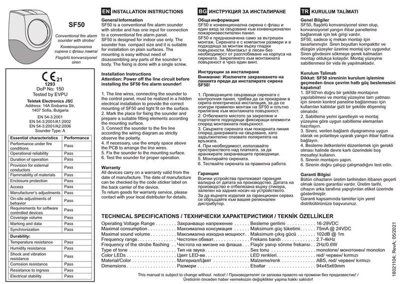
The signalling interface of TFNET consists of 6 LED, which can be used by the user to understand the functional states of the
communicator.
The table describes the functions and reporting modes of the LED on the front panel of the communication interface.
As required by EN 54-2 regulations concerning light signals, the ON/OFF flashing frequency of the LED is:
• 2.5 sec ON / 2.5 sec. OFF (slow flashing)
• 0.5 sec ON / 0.5 sec. OFF (fast flashing)
Notification Colour Type of notification Notification modes
POWER SUPPLY Green Reports the power supply status of the
device
Off Power supply off
On Power supply on
Green
Indicates the status of the connections of the
channels: SERVER 1 - SERVER 2
TECNOALARM TECNOSERVER
TECNOALARM SERVICE
Off No communication in progress
Slow flashing Data transfer in progress
On Ongoing communication
Green Displays the connection status of the
channel: TECNO OUT
Off No communication in progress
Slow flashing Data transfer in progress
On Ongoing communication
Green Displays the connection status of the
channel: MODBUS
Off No communication in progress
Slow flashing Data transfer in progress
On Ongoing communication
NOTIFIED EVENTS Red Reports the transmission states of the
notifications to remote receiving devices
Off No transmission in progress
Quick flashing Notification transmission in progress
On Notification transmission performed successfully
REGISTERED Red Status of the Dynamic DNS service
Off DDNS disabled
Slow flashing DDNS registration in progress
Quick flashing DDNS registration error
On DDNS registered
5.1 - Front panel
5.2 - LED

TFNET
14

TFNET 15
Access codes to factory programmed levels
L'accesso di livello 1 non è subordinato a password
Access to level 2
+ +
Access to level 3
+ +
Access to level 4
+ +
08/03/2016 08:00:00Access level 1
Level 2 Level 3 Level 4
Release: 1.3.00 ENG
Control panel working
Fire control panel
The TFAXFIRE Systems provide 4 access levels and 10 access codes.
The levels are: Level 1, Level 2, Level 3 and Level 4.
The table "Factory set access codes to levels" illustrates the sequence of keys used to access the Levels.
Access key to the level + Code + Confirmation Key.
Level 1
The control panel, in standby mode, provides access to the functions reserved to Level 1. Without having to enter a code, you can
perform the following operations:
A - Access the upper levels with the keys: 1 or 2 or 3 and the relevant password
B - Acknowledge the alarm pressing the ACKNOWLEDGE key
C - Display the previously acknowledged ongoing alarms, stored in the event categories folders.
Level 2
It is possible to access Level 2 by pressing the key 1 and entering the relevant User Code.
At level 2, it is possible to perform all the operations of the previous level and the following operations:
A - Reset the unit pressing the RESET key.
B - Switch the unit operating state: manned to Unmanned and vice versa.
C - Manually activate an Evacuation alarm.
D - Access the list of menus reserved to Level 2.
Level 3
It is possible to access Level 3 by pressing the key 2 and entering the relevant "Installer/maintainer" code of the staff authorized to
edit important operating parameters. At level 3 it is possible to perform all the operations of the previous levels and to access the
menus reserved to Level 3.
Level 4
It is possible to access Level 4 by pressing the key 3 and entering the code of the "Staff authorized by the manufacturer", that is
highly qualified personnel authorised by the manufacturer to carry out technical services of particular importance.
To access level 4 it is also necessary to close the "KEY" jumper of the control panel.
At level 4 it is possible to perform all the operations of the previous levels and to access the menus reserved to Level 4.
Attention: The operations described in this chapter illustrate functions accessible at System level.
Therefore, these operations can only be performed by accessing the Central Unit that manages the System on which the TFNET
communication interface operates.
None of the operations described in this chapter may be performed via the equipment described in this manual.
6 - OPERATING MODES OF THE SYSTEM
6.1 - Access levels and codes

TFNET
16
...
...
Menu name Menu function
4.1 Test light signaling The menu starts a test procedure of the display and of the signalling LED of the control panel
4.2 Sound test The menu allows to test the operation of the centre speaker in siren mode
4.3 Test words The menu allows to test the operation of the centre speaker in speaker mode
4.4 Test system The menu allows to select the programmed Zones to submit them to the functional test procedure
Press
the access key
Enter
the password
Confirm
the password Select the menu with the arrow keys
or directly with the number keys
Confirm
the selection
28/10/2016
Functioning test menu
Test light signaling
Sound test
Test words
Test system
Livello di accesso 2 08:18:59
Menus which can be accessed at level 2
Level 2 access allows authorized users provided with password to browse and use the appropriate menus.
For each available menu, the table shows the quick selection number (index number), the menu name and its function.
Access Mode
To access the menus follow the operating sequence illustrated in the diagram, or read the following instructions.
The password used in the example is the one set at the factory. Replace the numerical sequence shown with your password.
The password consists of five digits; after entering, confirm it with the OK button.
The blue cursor displayed on the left side of the menu list is the selection pointer. The pointer can be moved using the arrow keys
up or down. The choice of the menus can also be done by entering the quick selection number.
6.2 - Access level 2
The control panel, via the test menu, allows to perform the functioning test of the LED of the TFNET communication interface.
The test menu includes 4 sub-menus with which it is possible to perform a few simple functioning tests. The first menu allows to
check the display and the LED of the control panel as well as the LED of the TFNET communication interface.
6.3 - Functioning test
4.1 - Test light signaling
The light signaling test is used to check the operation of the display and the LED of the control panel as well as the LED of
the TFNET communication interface. At test start, the control panel turns on steadily all the LED of its front panel, the display
alternates between two sample images to prove its functionality.
At the same time the System turns on steadily all the LED of the front panel of the TFNET device.
Select the menu
with the arrow keys
or enter its index number
Access
the menu
To exit setup, press one
or more times the ESC key
until the display shows
"Control panel ON"
Type the level 2
password
[ ]
28/04/2016 08:18:59Access level 1
08/03/2016 08:00:00Access level 1
Level 2 Level 3 Level 4
Release: 1.3.00 ENG
Control panel working
Fire control panel
28/04/2016 08:18:59Access level 2
12:12:59 27/09/14
User
Level 2 menu
Last change
Devices exclusion
Events display
Functional test
Change user password
Test light signaling Start test
Control panel ON

TFNET 17
TECNO OUT
DDNS
TFNET 121016
*2903000024*
*2903000024*
RJ45
7 - ELECTRONIC BOARD
RS485 BUS RS485 MODBUS BUS
1+Supply positive 5NCNot connected (terminal not used)
2-Supply negative 6-Reference negative of RS485 BUS output
3ACommunication channel A 7ACommunication channel A
4BCommunication channel B 8BCommunication channel B
Ethernet RJ45 connector Identification Colour Function
1White / Green 5White / Blue RUN LED Green LED monitoring the functional state of the device.
Flashing: normal operation state
2Green 6Orange
3White / orange 7White / Brown LINE LED Red LED signalling that the device is using the Ethernet line
4Blue 8Brown
Jumper JP6 - Termination of RS485 serial line
Open With the jumper open, the Bus is not terminated. Open the jumper when the device is not the last device connected
on the Bus. Condition valid for both wiring configurations of the line Bus: open or closed
Closed With the jumper closed, the Bus is terminated. Close the jumper when the device is the last device connected on the
Bus. Of course only if the connection Bus is in open line configuration.
Identification Normal condition Function
JP1 - RESET Open Hardware reset
JP2 - BOOT Open Used to update the firmware of the product (RJ45 port Ethernet connection)
JP3 - DEFAULT Open No function (reserved for future developments)
SW1 Serial address setup
Address Dip 1 Dip 2 Dip 3 Dip 4 Dip 5 Dip 6 Address Dip 1 Dip 2 Dip 3 Dip 4 Dip 5 Dip 6
0OFF OFF OFF OFF OFF OFF 9ONOFF OFF ON OFF OFF
1ONOFF OFF OFF OFF OFF 10 OFF ON OFF ON OFF OFF
2OFF ON OFF OFF OFF OFF 11 ON ON OFF ON OFF OFF
3ONONOFF OFF OFF OFF 12 OFF OFF ON ON OFF OFF
4OFF OFF ON OFF OFF OFF 13 ON OFF ON ON OFF OFF
5ONOFF ON OFF OFF OFF 14 OFF ON ON ON OFF OFF
6OFF ON ON OFF OFF OFF 15 ON ON ON ON OFF OFF
7ONONONOFF OFF OFF 16 OFF OFF OFF OFF ON OFF
8OFF OFF OFF ON OFF OFF
Notes: setting address 0 disables the operation of the communicator. Accepted addresses range from 1 to 16.
All other logic combinations are reserved.
Identification MODBUS BUS balance
JP4 MODBUS
BALANCE
Open
RS485 MODBUS line not terminated
Closed
RS485 MODBUS line terminatedJP5 Open Closed
JP7 Open Closed

TFNET
18

TFNET 19
Configuration repeaters
28/10/2016
28/10/2016
28/10/2016
28/10/2016
Menu Configuration repeaters
Repeater 1
Repeater 2
Repeater 3
Repeater 4
Repeater 5
Repeater 6
Repeater 7
Repeater 8
Repeater 9
Repeater 10
Menu software options
Enabling 1
Enabling 2
Enabling 3
Enabling 4
Enabling 5
Enabling 6
Enabling 7
Enabling 8
Send
Reception
Menu software options: Enabling 5
00000000
00000000
00000000
00000000
00000000
00000000
00000000
00000000
Menu Configuration repeater 1
Enabling
Description
Voice msg
Type
Software options
Enabled
TFNET
00000000
Enabled
Disabled
Disabled
Disabled
Disabled
Disabled
Disabled
Disabled
Disabled
Disabled
Access level 3
Access level 3
Access level 3
Access level 3
08:18:59
08:18:59
08:18:59
08:18:59
Software licenses that allow to extend the capabilities of the device TFNET can be purchased at any time. At the time of purchase
a code is issued that must be entered in the configuration menu of the repeater. When a valid code is recognized, the device
enables the related functions.
8 - SOFTWARE OPTIONS
00000000
5 MODBUS
3 TECNO OUT
TFNET - Software options
Option Description Name Item no.
3TECNO OUT protocol management TFABIL-TECNO TF2TFABILTECNO
5MODBUS protocol management TFABIL-MODBUS TFTFABILMODBUS
Note: The option numbers not mentioned have not yet been assigned
Enabling of software options
Enabling of software options can only be performed from
the control panel setting menu "Repeaters".
Select and access the menu, select the address of
the repeater on which you want to assign the software
option.
Access the setting menu of the Repeater.
Select "Software options" and access the menu.
Select a row. e.g. select option 1 and access its entry form.
Enter the alphanumeric enabling code and exit the menu.
Send the enabling code to the device.
Select the item Send and confirm with the OK key.
Receive from device the status of its software options.
Select the item Receive and confirm with the OK key.
Check the mask of the software options of the device and
exit setup
00010000
5 MODBUS
3
Sosftware options
The enabling code consists of 8 numbers (either 0 or 1).
Number 0 indicates that the corresponding option is not active on the device, number 1 indicates that the corresponding option
is active on the device.
In the opposite example the only active option is number 5.
Select the software
options menu
Select the address
of the repeater
Access the repeater
Access the menu
Select the number of
the software option
Select Receive
and confirm
with the OK key
Select the character
Enter the character
Delete the last
character
At entry end
Select Send
and confirm
with the OK key
Access enabling code
entry form
Access the menu

TFNET
20
Table of contents
Other Tecnoalarm Fire Alarm manuals
Popular Fire Alarm manuals by other brands

Bosch
Bosch FMC-420RW-GSRRD installation guide

SL
SL SECURI4 Installation, operating, & maintenance instructions

Ziton
Ziton ZP755R-2 Installation sheet

Honeywell
Honeywell XL 800 Series Operator's manual

Global Fire
Global Fire ORION-EX V2 Installation operation & maintenance

Bosch
Bosch FAP-DO420 Operation guide

Tyco
Tyco 800 Service and maintenance instructions

Bosch
Bosch AVENAR FAP-425 Operation guide

Zeta
Zeta QT/1 User manual, maintenance guide & log book

Simplex
Simplex SafeLINC 4020 troubleshooting guide

Carrier
Carrier Ziton ZP3 user guide

Fire-Lite Alarms
Fire-Lite Alarms MS-5012 Installation, operation, and programming manual