Levitronix PuraLev LCO-2000 User manual

User Manual for LCO-2000 Console
www.levitronix.com
PL-4070-00, Rev01, DCO# 20-092
First Release: 15-Jun-17
Last Update: 02-Apr-20
PuraLev®Console
LCO-2000
PuraLev®2000SU and PuraLev®2000MU
USER MANUAL
This manual contains information necessary for the safe and proper use of the PuraLev®LCO-2000 Console.
Included are specifications for the standard configurations and instructions regarding its use, installation,
operation, adjustment, inspection and maintenance. For detailed description of the menu structure and the
configuration possibilities with the touch screen of the LCO-i100 console user interface the console software
manual PL-4067-00 can be consulted. For all in this manual revision described configurations and features
the LCO-i100 console software V1.04 R13 or higher is needed. For special configurations of the system
refer to accompanying information. Please familiarize yourself with the contents of the manual to ensure the
safe and effective use of this product. After reading this manual, please store the manual where the
personnel responsible for operating the pump system can readily refer to it at any time.

User Manual for LCO-2000 Console
www.levitronix.com
PL-4070-00, Rev01, DCO# 20-092
2
Table of Contents
1SAFETY PRECAUTIONS...............................................................................................................................................................3
2SPECIFICATIONS..........................................................................................................................................................................4
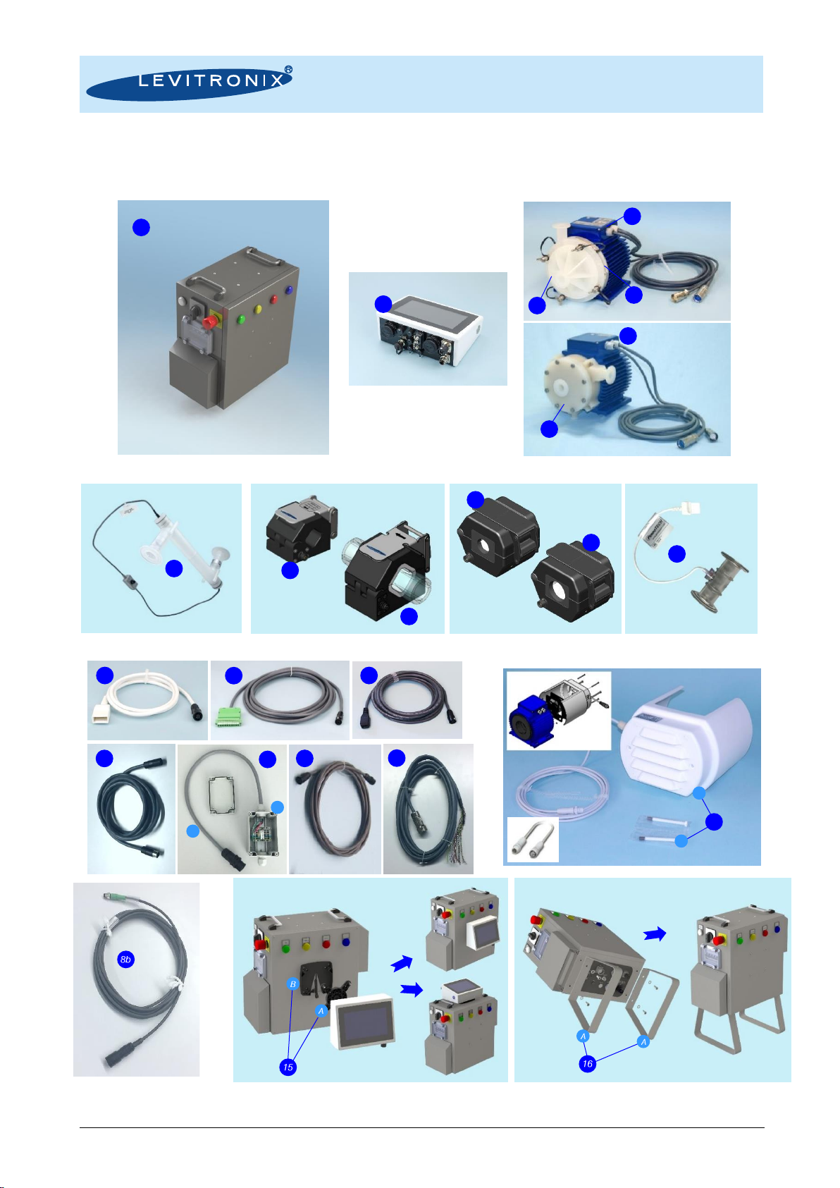
2.1 Specification of Console Components...................................................................................................................................4
2.2 System Overview and General Specification.........................................................................................................................6
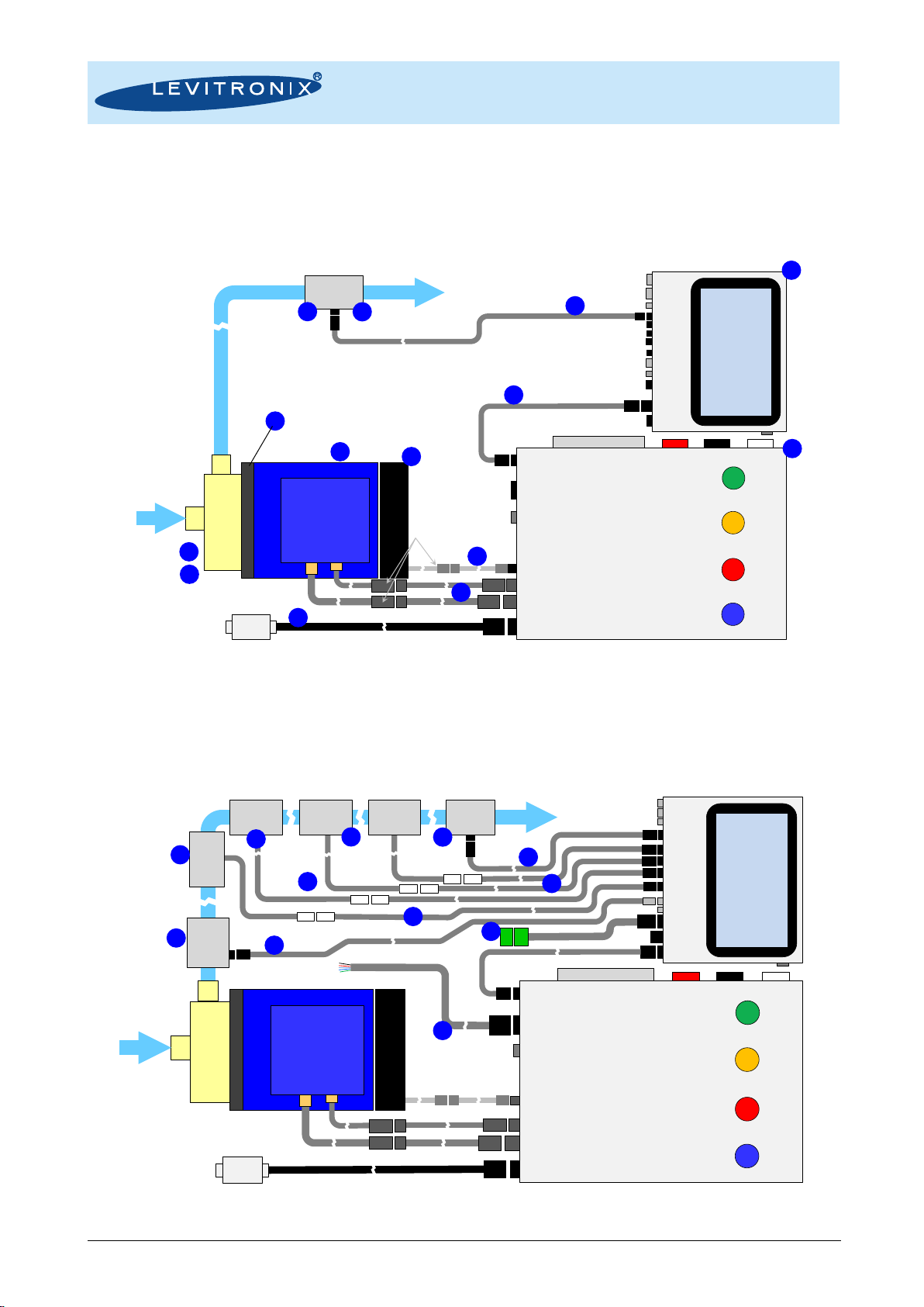
2.2.1 Basic Stand-Alone System Configuration with LCO-i100 .................................................................................................................................6
2.2.2 Extended System Configuration with LCO-i100................................................................................................................................................6
2.3 General Environmental Conditions........................................................................................................................................7
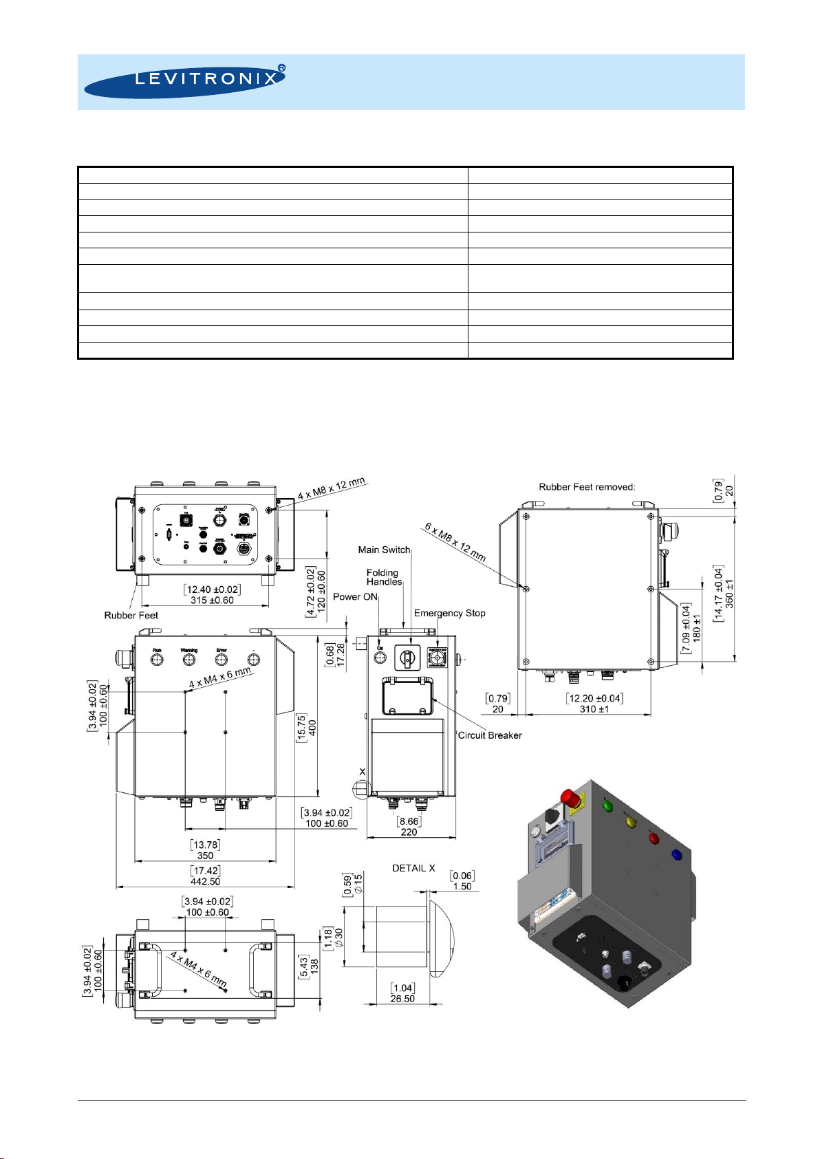
2.4 Basic Dimensions of Consoles..............................................................................................................................................7
3ENGINEERING INFORMATION.....................................................................................................................................................9
3.1 IP Rating...............................................................................................................................................................................9
3.2 Temperature Monitoring........................................................................................................................................................9
4INSTALLATION ...........................................................................................................................................................................10
4.1 Mechanical Installation of LCO-2000...................................................................................................................................10
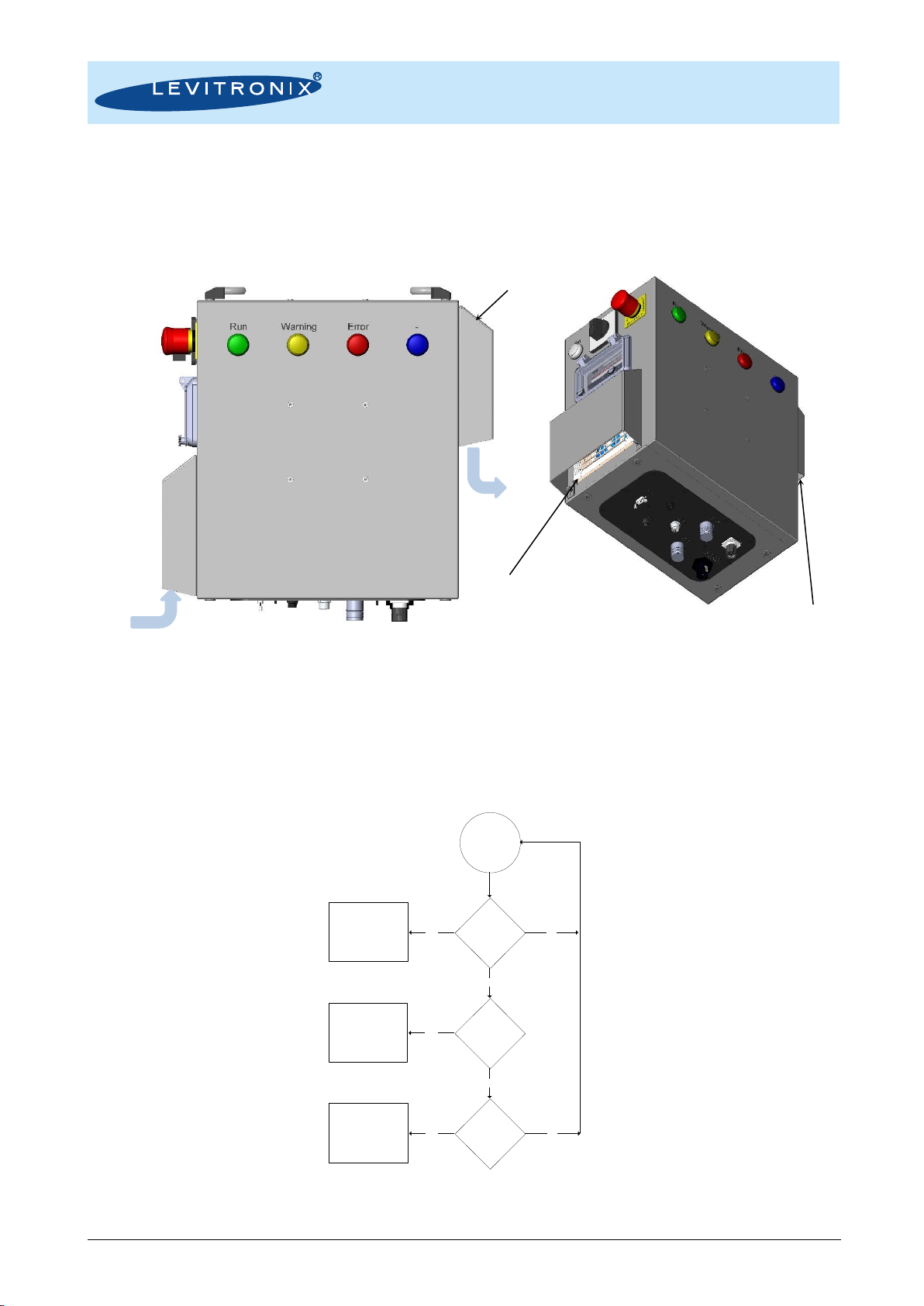
4.1.1 Mounting Positions...........................................................................................................................................................................................10
4.2 Mechanical Installation of LCO-i100....................................................................................................................................10
4.3 Electrical Installation of LCO-2000 ......................................................................................................................................11
4.3.1 Connection Overview.......................................................................................................................................................................................11
4.3.2 General Installation Instructions ......................................................................................................................................................................12
4.3.3 Installation of Motor Connectors to Console ...................................................................................................................................................14
4.3.4 RS232 Interface...............................................................................................................................................................................................14
4.3.5 PLC Interface...................................................................................................................................................................................................15
4.2 Electrical Installation of LCO-i100 .......................................................................................................................................16
4.2.1 Overview and Reference .................................................................................................................................................................................16
5OPERATION................................................................................................................................................................................17
5.1 Basic System Operation......................................................................................................................................................17
5.1.1 Start-Up............................................................................................................................................................................................................17
5.1.2 Power Down.....................................................................................................................................................................................................17
5.1.3 Auto-Resume Feature LCO-i100.....................................................................................................................................................................18
5.1.4 Software Update ..............................................................................................................................................................................................18
6MAINTENANCE...........................................................................................................................................................................19
6.1 Cleaning..............................................................................................................................................................................19
7TROUBLESHOOTING .................................................................................................................................................................19
8TECHNICAL SUPPORT...............................................................................................................................................................19
9APPENDIX...................................................................................................................................................................................20
9.1 Regulatory Status ...............................................................................................................................................................20
9.1.1 CE Marking ......................................................................................................................................................................................................20
9.1.2 IECEE CB Safety Certification.........................................................................................................................................................................20
9.1.3 NRTL/ETL Safety Certification and Marking ...................................................................................................................................................20
9.1.4 Disposal of Equipment –WEEE Directive 2012/19/EU...................................................................................................................................20
9.2 Symbols and Signal Words.................................................................................................................................................21

User Manual for LCO-2000 Console
www.levitronix.com
PL-4070-00, Rev01, DCO# 20-092
3
1 Safety Precautions
The PuraLev®Console LCO-2000 is designed to be used in research laboratories and industrial production
environments in life science markets like biotech and pharmaceuticals. Installation shall be done by qualified
personnel only. Following safety precautions and all “CAUTION”, “WARNING” and “DANGER” indications in
the relevant sections shall be followed.
Concerning safety precautions for motor, pump and sensors refer to the corresponding manuals.
CAUTION
Do not under any circumstances open the console enclosure. Levitronix®does
not assume responsibility for any damage, which occurs under such
circumstances.
!
WARNING
Hazardous voltage may be present.
Always switch off the LCO-2000 console before performing any changes to the
connections, the positioning and before doing other maintenance activities.
Hazardous voltage is present until 60 seconds after switchingoff. Donothandle
the console during this time.
Use mains supply with a proper grounding. A mains protection with residual or
leakage current circuit breaker is recommended.

User Manual for LCO-2000 Console
www.levitronix.com
PL-4070-00, Rev01, DCO# 20-092
4
2 Specifications
2.1 Specification of Console Components
Figure 1: LCO-2000 console with compatible motors and pump heads
Figure 2: Sensors compatible with LCO-i100 user interface console (in context with LCO-2000 console)
Figure 3: Accessories (cables and others)
2c
2a
7
2c
12
1a
13
a
13
a
A
1b
B
8
9
10
2b
2d
18
C
A
4a
4b
3
6
5a
5b

User Manual for LCO-2000 Console
www.levitronix.com
PL-4070-00, Rev01, DCO# 20-092
5
Pos.
Component
Article Name
Article #
Characteristics
Value / Feature
1a
PuraLev®Console
(User Interface)
LCO-i100.1-01
100-30501
Supply Voltage / Power
Housing Rating / Weight
24 VDC with 50 W or 160 W supply (Supply available on LCO-2000 console)
IP54 3/ 1.6 kg
Interfaces
Multi-touch screen 7”, 3 pressure sensors, 2 flow sensors, 1 temperature sensor
PLC, LAN, USB
Pump Motors
PuraLev®i30/ i100 integrated driver. (Only one driver connected at the same time).
Certifications
Certifications: CE, IECEE CB scheme, ETL (NRTL) listed. 2
1b
PuraLev®Console
(Drive Unit)
LCO-2000.1-01
100-30503
Supply Voltage / Power
1 x 200 –240 ± 10% 1x 13.5 -11.0 A ± 10%, / 2100 W, 50/60 Hz
3 x 200 –240 ± 10% 3 x 8.5 –8.0 A ± 10%, / 2100 W, 50/60 Hz
Housing Rating / Weight
IP54 / 15.8 kg
Interfaces
RS232 to LCO-i100 (including 24VDC supply, fan cooling module.
PLC and RS232 for operationl without LCO-i100.
Certifications
CE, IECEE CB scheme, ETL (NRTL) listed.
Table 1: Basic specifications of standard LCO-2000 console with user interface console LCO-i100
Note 1: AC mains cable to be ordered separately according. Note 2: Not available on units older than 2018/2019. Note 3:Units older than 2018/19 are IP40 rated.
Pos.
Component 2
Article Name
Article #
Characteristics
Value / Feature
2a
Multi-Use
Pump Head
CP-4.11 (with drain port)
CP-4.19 (no drain port)
100-90245
100-90458
Wet Materials / Fittings
PVDF, PFA and EPDM (FDA, USP Class VI, BSE/TSE/animal-free) / Triclamp 1”
Max. Flow / Max. Diff.-Press.
140 liters/min (37 gallons/min) / 4.1 bar (59.5 psi)
Sterilization Methods
CIP (clean in place), SIP (steam in place), Autoclaving
2b
Single-Use
Pump Head
DCP-2000.2 1
(Needs pump head socket
mounted on motor)
100-90889
Wet Materials
Polypropylene (FDA, USP Class VI, BSE/TSE/animal-free) / Triclamp 1”
Max. Flow / Max. Diff.-Press.
140 liters/min (37 gallons/min) / 4.3 bar (62.4 psi)
Sterilization Methods
Gamma radiation up to 40 kGy.
2c
Motor
LPM-2000.7
100-10059
Housing
Epoxy (anti-corrosive) coated aluminum, waterproof (IP67)
Cable / Connectors
2x 3m cables with PVC jacket / 2x circular (M23, IP-67)
2d
Pump Head Socket
PHS-2000.2
100-90891
Mounting Type / Material
Mounting with 4x 25mm screws, anodized aluminum
Table 2: Specification of standard pump motors and single-use pump heads compatible with LCO-2000 console
Note 1: Gamma irradiated options available. Note 2: See Levitronix®technical brochures of PuraLev®2000SU and PuraLev®2000MU for more detailed specifications
Pos.
Component
Article Name
Article #
Fitting
Wet Material
Note
3a
3b
LEVIFLOW®
Single-Us Flow Sens.
LFS-20SU.1-Z (80 lpm)
LFS-20SU-Z-SC1 1
100-30483
100-30464
Triclamp 1”
Polypropylene (FDA, USP Class VI,
BSE/TSE/Animal free)
Gamma stable for upto 40 kGy.
See Levitronix®technical brochure of LFS-SU single-
use sensor series for more detailed specifications and
other sizes.
Table 3: Spec. of LEVIFLOW®single-use high-precision (1% accuracy of read.) flow sensors compatible with LCO-i100 in context with LCO-2000 console
Note 1: Extended calibration for wider accuracy range. Note 2: Sensors available with gamma irradiation option (see LEVIFLOW®SU literature). Note 2: Needs LCO-i100 console software LCO V1.04 R12 or higher.
Pos.
Component
Article Name
Article #
Liquid
Tubing
Tube ID x OD
Note
4a
4b
LEVIFLOW®Clamp-On
Flow Sensors LFSC-D
LFSC-22D-005 (80 lpm)
LFSC-30D-001 (160 lpm)
100-30391
100-30414
Water @
20°C/37°C
Silicone/C-Flex®1
3/4” x 1”
1” x 13/8”
See Levitronix®technical brochure of LFSC-D or
LFSC-iX clamp-on sensor series for detailed
specifications or other sizes.
Default activated calibration set is Silicone at
37°C liquid temperature.
5a
5b
LEVIFLOW®Clamp-On
Flow Sensors LFSC-iX
LFSC-i25X-001 (80 lpm)
LFSC-i35X-001 (160 lpm)
100-30480
100-30481
Water @
20°C/37°C
Silicone, C-Flex®
and TPE
3/4” x 1”
1” x 13/8
Table 4: Specification of LEVIFLOW®clamp-on flow sensors compatible with LCO-i100 in context with LCO-2000 console
Note 1: C-Flex®is a registered trademark of Saint Gobain Performance Plastics, 2015. All rights reserved.
Pos.
Component
Article Name
Article #
Fittings
Specification
Wet Material
Note
6
PendoTECH Single-Use
Pressure Sensor
PREPS-N-1-1
190-10374
1” Sanitary Clamp
Pressure range:
-0.48 to 5.2 bar
Polysulfone
See PendoTECH literature for more
detailed specifications.
7
Single-Use
Temperature Sensor
--
--
Barb,
Dip. Probe
Temp. range:
0 –70°C
Polysulfone
Stainless steel
Contact Levitronix®for more
information.
Table 5: Specification of single-use pressure and temperature sensors compatible with LCO-i100 console
Pos.
Component
Article Name
Part #
Characteristics
Special Feature / Description
8a
LEVIFLOW®
Interconnect Cable
LFI-C.1-30 (3m)
190-10308
Cable Jacket Material
Main Purpose
PVC
Connection between sensor and console
8b
IP Cable Signal 4 Wires
ICS-3.1-30 (3m)
190-10447
Cable Jacket Material
Main Purpose
PUR
Connection between LFSC-iX flow sensors and console.
9
Pressure Sensor
Adaptor Cable
LPE-1.1-30 (3m)
190-10354
General Specifications
Main Purpose
Circular console connector, watertight on console side.
Connection of single-use pressure sensors to console.
10
Temperature Sensor
Adaptor Cable
LTE-1.1-30 (3m)
190-10353
General Specifications
Main Purpose
Circular console connector, watertight on console side.
Connect single-use temperature sensors to console. For barb sensors and
dip probe.
11
IPS Cable Signal 12
Wires
ICS-2.1-50 (5 m)
190-10347
Cable Material / Wires
Connection In / Out
Main Purpose
PVC jacket / 12x 0.14 mm2and shielding
Connector with screw type plug for open wire connection / Circular Hirose
type
General connection to PLC of LCO-i100 console.
12
IP Adaptor Cable
Hybrid
ICH-1.2-03 (0.3 m)
ICH-1.2-08 (0.8 m)
ICH-1.2-30 (3 m)
190-10384
190-10385
190-10329
General Specifications
Main Purpose
Special Note
Circular console and driver side connector, watertight.
Connection of LCO-i100 to LCO-2000
0.3 m for mount. LCO-i100 front side of LCO-2000 and 0.8 m for top side.
13
AC Mains Cables
(for Console power supply)
AMC-3.3-60 (6 m, 1/3-Phase)
190-10442
Cable Material / Wires
Cable Specifications
Wiring Box (C) Specific.
PVC jacket (A) / 4x AWG14 (2.5 mm2)
IP68 connector (B) on console side, IP67 wiring box for 1 or 3 phase wiring
IP67 and UL508A / Materials: PC, PUR, PA, SS / Size: 120x80x86 mm
14
Fan Cooling Module
FCM-2000.1
190-10390
Housing / Cable Spec.
Supply Spec. / IP Rating
PP (+Talk.) / PVC jacket, 3m, circ. watertight connector on console side.
24 VDC, 33.5 W / IP-65 (fan is IP68 rated).
15
Console Mounting Kit
CMK-1.2
190-10443
Parts Specifications
Purpose
(A) Mount. adaptor LCO-i100,(B) Mount. Adapt. LCO-2000, Mount. screws
Mounting LCO-i100 on front or top side of LCO-2000 console.
16
Console Mounting Kit
CMK-2.1
190-10411
Parts Specifications
Purpose
(A) 2 mounting feets and mounting screws.
Vertical bottom mounting of LCO-2000 console.
17
Adaptor/Extension
Cable Power / Sensor
MCIP-600.1-30/MCIS-600.1-30 (3m)
190-10361 / 62
Cable Material / Connect.
Purpose
PVC jacket / circular to circular connector
Extension of motor cables (power and sensors).
18
FCM Interconnect
Cable
FCC-1.2-30 (3m) 1
190-10414
Cable Material / Connect.
Purpose
PP jacket / circular to circular connector
Extension of fan cooling module cable.
19
LCO Adaptor Cable
(for PLC)
LSE-1.1-50 (5m)
190-10417
Cable Material / Wires
Connection In / Out
Main Purpose
PVC jacket / 12x 0.12 mm2and shielding
Open wire / Circular metallic type
Connection to PLC of LCO-2000 console (remote without LCO-i100)
Table 6: Specification of standard cables and other accessories

User Manual for LCO-2000 Console
www.levitronix.com
PL-4070-00, Rev01, DCO# 20-092
6
2.2 System Overview and General Specification
2.2.1 Basic Stand-Alone System Configuration with LCO-i100
With the stand-alone pump system configuration, as illustrated in Figure 4, the speed of the pump can be manually set,
and the flow can be monitored with a LEVIFLOW®flow sensor. The mode of operation can be easily switched to a flow
control setup, where the flow is set manually on the 7” multi-touch screen controlled by the integrated PC.
Figure 4: Stand-alone pump system configuration of console with flow monitoring or control
(Speed or flow setting via integrated touchscreen menu of the LCO-i100 console.)
2.2.2 Extended System Configuration with LCO-i100
Figure 5 illustrates the extended capabilities of the console for advanced fluid handling applications. The
connection of up to two single-use pressure sensors enables pressure monitoring. A standard interface for a
temperature sensor facilitates temperature monitoring.
Figure 5: Extended system configuration of console for advanced fluid handling
Power PuraLev®2000 Motors
Sensors PuraLev®2000 Motors
Supply and Control of
Fan Cooling Modul FCM-2000
Emergency
Off
Breaker (Accessible Door)
LED s for
System Status
Console
LCO-2000
(Driver Unit)
AC Mains Cable
Fan Cooling Modul
MagLev
Motor
AC Input
Communication and
24 VDC Supply Interface
Fluid In Single-
Use
Pump
Head
Power On/Off
Fluid Out
Flow Sensor
LFS-D
LFS-SU
Power
On/Off LED
On/Off
AC Supply Input
Wiring Box
Multi-Touch
Screen 7"
USB
Power to
Integrated
Driver
Flow Sensor
Multi-Touch
Screen 7"
USB
DC Supply
Input
IPS Driver
Temperature
Pressure 1
Pressure 2
Flow Sensor Console
LCO-i100
(User Interface)
Analog In./24V
PLC
Power PuraLev®2000 Motors
Sensors PuraLev®2000 Motors
Supply and Control of
Fan Cooling Modul FCM-2000
Breaker (Accessible Door)
LED s for
System Status
Console
LCO-2000
(Driver Unit)
AC Mains Cable
Fan Cooling Modul
MagLev
Motor
AC Input
Communication and
24 VDC Supply Interface
Fluid In Single-
Use
Pump
Head
Fluid Out
Flow
LFSC-D
LFS-SU
Inline
Temp.
Sensor
Pressure
Sensor 3
PLC (Pump Controller)
RS232 (Pump Controller)
Emergency
Off Power
On/Off LED
On/Off
Power On/Off
LAN (TCP/IP)
AC Supply Input
Wiring Box
Pressure
Sensor 2 Pressure
Sensor 1 RS485 (Remote)
RS485/24V
Pressure 3
Flow
Sensor
LFSC-iX
2c
2d
Pump Head Socket
(only for DCP-2000
pump heads).
11
14
1a
2b
4
Option Multi-Use
Pump Head..
2a
8a
13
3
Fan Cooling Module
(Only for high
performance needed
See manuals of PuraLev
2000SU/MU)
1b
6
8a
10
7
11
6
9
18
17
18
Direct connection to
console possible.
6
9
8b
6

User Manual for LCO-2000 Console
www.levitronix.com
PL-4070-00, Rev01, DCO# 20-092
7
2.3 General Environmental Conditions
Usage
Indoor (Laboratory, Industrial environments)
Altitude
Up to 2000 m
Operating ambient temperature
10 to 40 °C
Storage ambient temperature (Extremes for Transportation)
-20 to 70 °C
Operating humidity range (relative humidity)
15 –95% (non-condensing)
Storage humidity range (relative humidity) (Extremes for Transportation)
15 –95% (non-condensing)
Normal storage conditions
Ambient temp.: 20 to 30 °C
Relative humidity: 50% (non-condensing)
Mains supply fluctuations
10% of nominal voltage
Transient over-voltages typically present on the mains supply
Surge immunity according to EN 61000-4-5
Pollution degree
2
IP rating
IP54 for LCO-2000 and LCO-i100
Table 7: Environmental conditions for LCO-2000 and LCO-i100 consoles
2.4 Basic Dimensions of Consoles
Figure 6: Basic dimensions (in mm) of console LCO-2000
(Dimensions without tolerances are for reference only.)
Threads for wall-mounting
4 removable rubber feet
(standard delivery with console)

User Manual for LCO-2000 Console
www.levitronix.com
PL-4070-00, Rev01, DCO# 20-092
8
Figure 7: Basic dimensions (in mm) of AC cable AMC-3.3
(Dimensions without tolerances are for reference only.)
Figure 8: Basic dimensions (in mm) of console LCO-i100
(Dimensions without tolerances are for reference only.)
Cable Bushing:
Tightening torque: 3 Nm
Clamping range: 8 –13 mm.
4 Mounting Holes
for screws inside the box.

User Manual for LCO-2000 Console
www.levitronix.com
PL-4070-00, Rev01, DCO# 20-092
9
3 Engineering Information
3.1 IP Rating
The console LCO-2000 is designed and tested to meet IP54. A temperature controlled fan inside the console,
which is protected by a watertight filter and a sealed cover as illustrated in Figure 9 provides cooling of the
electronics inside the console.
Figure 9: IP rating and cooling concept of console LCO-2000
3.2 Temperature Monitoring
To avoid overheating of the system, the LCO-2000 console temperature is monitored (within the pump
controller). If the temperature exceeds 70°C (158°F) for a duration of more than 10 minutes, the system goes
into an error state and the attached pump stops. At 80°C (176°F) in the controller the system stops immediately.
Start
Temperature
Monitoring
WARNING
YES
Temperature
> 70°C ?
Temperature
> 80°C ?
YES
YES
ERROR
Temperature
higher than 70°C
for more than 10
minutes?
NO
ERROR
YES
NO
NO
Figure 10: Temperature monitoring of console LCO-2000 (within the pump controller)
Cooling Air In (Fan side)
Protective
Sealed Cover
Cooling Air Out
Accessible
Sealed Circuit
Breakers
Filter Holder with
Watertight Air Filter
Protective
Sealed Cover
Filter Holder with
Watertight Air Filter

User Manual for LCO-2000 Console
www.levitronix.com
PL-4070-00, Rev01, DCO# 20-092
10
4 Installation
4.1 Mechanical Installation of LCO-2000
4.1.1 Mounting Positions
Figure 11: Mounting positions of console LCO-2000
For wall-mounting of the console the 4 pre-assembled rubber feet on the back side have to be removed. The
underlying 6 M8 threads can be used for the wall-mounting according to the specifications in Figure 6. For the
mounting solution design the weight of 15.8 kg has to be considered.
The Console Mounting Kit CMK-2.1 is available to place the LCO-2000 vertically on the floor (see Table 6 for
the kit).
4.2 Mechanical Installation of LCO-i100
The user interface console LCO-i100 is made for desktop operation on a horizontal surface or can be wall-
mounted to an appropriate vertical surface. For wall-mounting the four pre-assembled rubber stands on the
bottom shall be removed. The underlying four M4 threads can be used for the wall-mounting according to the
specifications in Figure 8. For the mounting solution design, the weight of 1.6 kg shall be considered.
The Console Mounting Kit CMK-1.1 is available to mount the LCO-i100 on the front or top side of the LCO-
2000 console (see Table 6 for the kit).
Figure 12: Mounting of LCO-i100 with Console Mounting Kit CMK-1.1
(Includes snap in feature for easy removal of LCO-i100)

User Manual for LCO-2000 Console
www.levitronix.com
PL-4070-00, Rev01, DCO# 20-092
11
4.3 Electrical Installation of LCO-2000
4.3.1 Connection Overview
Figure 13: Interfaces of console LCO-2000.1
#
Interface
Description
Specification/Purpose/Note
1
AC Supply
Mains supply input.
1 x 200 –240 ± 10% 1 x 13.5 –11.0 A ±10% 2100 W 50/60 Hz
3 x 200 –240 ± 10% 3 x 8.5 –8.0 A ±10% 2100 W 50/60 Hz
See description in Section 4.3.2 for details.
2
Control Unit
Communication to LCO-i100
RS232 interface with 24VDC supply.
3a
Motor Power PuraLev®2000
Power connector for LPM-2000 motors.
M23 metallic connector.
3b
Motor Sensor PuraLev®2000
Sensor connector for LPM-2000 motors.
M23 metallic connector.
4
RS232
RS232 to internal controller.
For operation without LCO-i100.
For operation with Levitronix®Service Software or remote control with
other devices.
5
PLC
PLC of internal pump controller.
For operation without LCO-i100.
4x digital outputs, 4x digital inputs, 1 analog output (5V), 1x analog input
(10V), 1x analog input (4-20mA), 24VDC supply output.
6
FAN Supply and Control
For Fan Cooling Module FCM-2000.1
24 VDC supply and speed control of motor cooling fan.
7a
7b
Flow
Flow PLC
Not used.
For future purposes.
8a
8b
8c
8d
LED 1 –Green.
LED 2 –Yellow.
LED 3 –Red.
LED 4 –Blue.
Run
Warning
Error
not assigned
Motor is running.
A warning has occurred.
An error has occurred.
For future use.
9
LED Power On/Off
White when supply is present and
console is switched on.
Indicates presence of mains supply.
10
Switch Power On/Off
Switch of mains.
Rotational switch.
11
Emergency Off
Twisted release type.
Product standards IEC/EN 60947-5, UL 508, CSA-C22.2, CE
12
Breaker Box
Circuit breakers.
For AC supply of signals and pump controller.
13
14
15
Type Label
Serial Number Label
ETL/NRTL label
--
--
Table 8: Interface specifications of console LCO-2000.1
10
11
13
14
9
12
1
2
3a
4
3b
5
6
8a
8b
8c
8d
7a
7b
15

User Manual for LCO-2000 Console
www.levitronix.com
PL-4070-00, Rev01, DCO# 20-092
12
4.3.2 General Installation Instructions
!
WARNING
Hazardous voltage may be present.
Always switch off the LCO-2000.1 console before performing any changes to
the connections, the positioning and before doing other maintenance activities.
Hazardous voltage is present until 60 seconds after switching off. Do not
handle the console during this time. Use mains supply with a proper grounding.
A mains protection with residual or leakage current circuit breaker is
recommended.
!
WARNING
Incorrect assembling of the “POWER INPUT” connector
➔
short circuit possible.
Assure that the pin assignments of the “POWER INPUT” connector are correct
before it is plugged in.
CAUTION
Air cooling system.
Do not block the vents and fans.
CAUTION
The On/Off switch and the Emergency Off switch must be accessible during
operation.
1. The console comes delivered with the fan-cover orientation for vertical wall-mounting. For desktop
operation the orientation of the covers can be changed according to Figure 15.
2. Connect the two motor connectors (“LPS-2000 Power Output” and “LPS-2000 Sensoric”) of a compatible
PuraLev®2000 motor to the console. Follow Section 4.3.3 to assure that the connectors are properly
mounted.
3. Connect the LCO-i100 to the control unit port using an interconnect cable (see Table 6).
4. To connect the AC mains to the console specific cables are available (see Table 6, AMC-3.3-xx) with
console connector on one side and wiring box on the other side (to assemble mains connectors of
choice). When assembling a mains connector with cable make sure that the pin connections are correct
as shown in Figure 14. The wiring box can be fixed or mounted on 4 wholes within the box (see Figure
7).
5. To secure the connectors, tighten all turn-lock connectors and assure the push-pull connectors are
properly connected.
6. Assure that all unused connectors are properly sealed with the corresponding protection cap.

User Manual for LCO-2000 Console
www.levitronix.com
PL-4070-00, Rev01, DCO# 20-092
13
Figure 14: AC power input connection (1 and 3-phase) of LCO-2000 console with AMC-3.3 cable
Figure 15: Changing orientation of ventilation covers from wall-mount to desktop
AC Mains
1-Phase
N
L
PE
U1-Phase = 200 – 240 Vrms ± 10%
Specification for AC Cable
To Mains 1-Phase:
Cable OD = 8 - 13 mm
Wires US: AWG14
Wires IEC: 2.5 mm2
Cable to Console
To Mains
Torque Specifications:
Cable Gland: 3 Nm
Housing Screws: 0.6 Nm
AC Mains
3-Phase
N
L1
PE
Specification for AC Cable
To Mains 3-Phase:
Cable OD = 8 – 13 mm
Wires US: AWG14
Wires IEC: 2.5 mm2
Cable to Console
To Mains
UDelta
L3
L2
UDelta = 200 – 240 Vrms ± 10%
UStar = 115 – 139 Vrms ± 10%
UStar

User Manual for LCO-2000 Console
www.levitronix.com
PL-4070-00, Rev01, DCO# 20-092
14
4.3.3 Installation of Motor Connectors to Console
The compatible PuraLev®2000 motors use an M23 threaded metallic Hummel connector type for the sensors
and the power cables. Check the connection according to the pictures in Figure 16. The connectors need to
be tightened such that the black O-ring is not visible any more. For an easier connecting it is recommended to
apply a small force on the connectors towards the enclosure during the tightening.
Figure 16: Wrong and correct Hummel connector type assembly of LPM-2000 motors
4.3.4 RS232 Interface
For usage of Levitronix®Service Software with a PC or for remote control with other devices than
the LCO-i100 the RS232 can be used. A relevant protocol for remote control is available on request
(see specifications for standard controller firmware E4.38).
CAUTION
Do not use the RS232 if the LCO-i100 is already connected to LCO-2000.
Pin#
Designation
Description
Note
1
5V
5V supply output
--
2
TX
Transmitting line of RS232
Baud Rate: 57600 Data Bits: 8
Parity: None Stop Bit: 1
3
RX
Receiving line of RS232
4
NC
Not connected.
--
5
GND
Ground
--
6
NC
Not connected.
--
7
NC
Not connected.
--
8
NC
Not connected.
--
9
NC
Not connected.
--
--
Connector
Housing
Shield
--
Table 9: RS232 Connector of Console LCO-2000 (to internal LPC-2000 controller)
Note 1: Serial RS232 cable with D-Sub connector (9 pin), not crossed, needed. Note 2: Standard controller firmware is E4.38
O-Ring visible
Wrong Connection!
O-Ring not visible
Correct Connection!
Power
Connector
Sensor
Connector
Sensor
Connector
Power
Connector

User Manual for LCO-2000 Console
www.levitronix.com
PL-4070-00, Rev01, DCO# 20-092
15
4.3.5 PLC Interface
Pin#
Wire
Color 13
Description
Standard
Designation 2
Typical Levels
Note
1
red-blue
Digital Out1
Status
Relay closed active, system on
Relay open not active, system off
Galvanic isolation with relay.
Relay: 1 A / 30VDC, 0.3A / 125VAC
Signal for LCO-2000 console LED Green.
2
grey-pink
Ground Digital Out1
3
brown-black
Digital Out2
Error
Relay closed active, system off
Relay open not active, system on
Galvanic isolation with relay.
Relay: 1 A / 30 VDC, 0.3 A / 125 VAC
When active, the system drives the impeller to 0 rpm and shuts
down. With a reset pulse the system can be re-initialized.
Signal for LCO-2000 console LED Red.
4
white-black
Ground Digital Out2
5
black
Digital Out3
Warning
Relay closed active, system not o.k.
Relay open not active, system o.k.
Galvanic isolation with relay.
Relay: 1A / 30 VDC, 0.3 A / 125 VAC
Indicates a system problem, but the system does not shut
down.
Signal for LCO-2000 console LED Yellow.
6
purple
Ground Digital Out3
7
red
Digital Out4
Configurable
--
Can be configured with Service Software (consult Service SW
manual PL-2034-00).
Signal for LCO-2000 console LED Blue.
8
blue
Ground Digital Out4
9
white-red
Digital In1
Reset
24 V active
0 V not active
Resets the error state.
Galvanic isolation with optocoupler.
Lowest input voltage for high level detection: 5V.
Typical 24 V/16 A, maximal 30V / 20 mA.
Highest input voltage for low level detection: 0.8 V
Minimum input resistance: 2.2 kOhm.
10
brown-red
Ground Digital In1
11
yellow-blue
Digital In2
Process Mode
24 V active
0 V not active
Switches between process and speed mode.
Same specification as for Digital In1.
12
green-blue
Ground Digital In2
13
pink
Digital In3
Enable
24 V active
0 V not active
Switches system on and off.
Same specification as for Digital In1.
14
grey
Ground Digital In3
15
brown
Digital In4
Not used.
--
--
16
white
Ground Digital In4
17
yellow
Analog Out1
Actual Speed
0 –5V 0-10000 rpm
Direct connection, no galvanic isolation.
Max. output current: 2 mA.
18
green
Ground Analog Out
19
brown-blue
NC
--
Not connected.
--
20
white-blue
NC
--
Not connected.
--
21
pink-brown
Analog In1
Reference Value
4-20 mA 0-10000 rpm (speed mode)
4-20 mA 0-100% (process mode)
450 Ohm input shunt.
22
white-pink
Ground Analog In1
23
yellow-grey
Analog In4
Actual Process
Control Value
0 –10V 0 –100%
Direct connection no galvanic isolation.
Minimum 7.8 kOhm input resistance.
24
grey-green
Ground Analog In4
25
grey-brown
24 DCV Supply
Supply
--
--
26
white grey
Ground of 24V Supply
NC
yellow-brown
NC
--
Not connected.
--
NC
white-yellow
NC
--
Not connected.
--
NC
brown-green
NC
--
Not connected.
--
NC
white-green
NC
--
Not connected.
--
NC
pink-green
NC
--
Not connected.
--
NC
yellow-pink
NC
--
Not connected.
--
--
EMC shield
Connector Housing
Table 10: PLC connector of Console LCO-2000 (to internal LPC-2000 controller)
1: Wires of compatible cables: LSE-1.1-xx 2: Designations are for controller firmware E4.38. 3: Wire size: 0.12 mm2.

User Manual for LCO-2000 Console
www.levitronix.com
PL-4070-00, Rev01, DCO# 20-092
16
4.2 Electrical Installation of LCO-i100
4.2.1 Overview and Reference
Figure 17 shows the various interfaces of the LCO-i100 console. The corresponding designations are
described in Table 11.
For detailed descriptions and installation instructions consult the LCO-i100 manual ( document # PL-4061-00)
available at Levitronix®.
Figure 17: Interfaces of console LPC-i100
Note 1: All connectors come delivered with a protective cap for a min. IP66 rated sealing if unused.
Note 2: When connected all connectors have a minimum rating of IP66.
#
Interface
Description
Specification/Purpose/Note
1
DC Supply Connector
Single-phase DC connection
24 VDC max. 6 A with external AC/DC supply 3 pin connector.
Software configurable Autoresume function. 1
2
Pump Driver
Power and signal connector for
IPD-30 and IPD-100 drivers.
--
3
Remote 1
RS485 for future purposes.
Not active. Internal usage.
4
PLC
Remote control.
Configurable designations.
2xdigital outputs (outputs software configurable to 24VDC 1),
2xdigital inputs, 1xanalog output (4-20 mA), 1xanalog input (4-20mA)
Note: All signals isolated.
5
Flow Sensor
LEVIFLOW®
Connection of flow sensors from the LFS-SU
and LFSC-D series.
Circular 6 pin snap-in connector.
Purpose: Flow control or monitoring.
6a
6b
6c
Pressure Sensor 1
Pressure Sensor 2
Pressure Sensor 3 1
Connection for singles-use pressure sensors 1,
2 and 3.
Needs adaptor cable (see Table 6).
Circular plastic snap-in connector (on console side).
Purpose: pressure monitoring and pressure control.
7
Temperature Sensor
Connection for 1 singles-use temperature
sensors.
Needs adaptor cable (see Table 6).
Circular plastic snap-in connector (on console side).
Purpose: Temperature monitoring.
8
Analog Input with 24VDC Supply
Multi purpose sensor input.
Current input 4-20 mA, 24 VDC supply (max. 0.5 A)
9
RS485 24VDC Out 1
Sensor input for new clamp-on flow sensors
LFSC-iX or other sensors with RS485.
Software functionality for new clamp-on sensor series LFSC-iX coming soon.
10
LAN Interface
TCP/IP Modbus
For connection to OPC devices.
11
USB Interface
Connection for a USB stick.
USB access for data debugging and software update through a USB stick.
12
Power Button
Switch on/off
Press shortly for controlled (confirmation by the user necessary) power off.
Press 4 s for immediate power off.
13
Touchscreen
Display and user touch interface.
7” multi-touch screen.
14
15
16
Type label
Serial number label
Certification (NRTL) label
--
--
Table 11: Interface specifications of console LPC-i100.1
Note 1: Not available on units older than 2018/19.
14
15
16

User Manual for LCO-2000 Console
www.levitronix.com
PL-4070-00, Rev01, DCO# 20-092
17
5 Operation
The console LCO-i100 contains a self-explaining touch screen user interface with various menus to
operate, configure and troubleshoot the system. In this section only the basic functions for a safe
usage are explained. For more details consult the LCO Console Software Manual PL-4067-00.
5.1 Basic System Operation
5.1.1 Start-Up
Switch on (power switch) the LCO-2000 and then the (press button) LCO-i100 console. The blue illuminated
power button of the LCO-i100 and the green illuminated LED on the front side of the LCO-2000 console indicate
that the consoles are switched on. After a while the following standard start-up menu appears on the touch
screen of the LCO-i100:
1. Start the pump by pressing the Start / Stop button and
entering a reference speed or flow. Choose between
Speed or Flow control mode.
2. For advanced operation, configuration and trouble-
shooting the menus Application, Info and Settings can be
used. For more details the LCO Console Software
Manual PL-4067-00 shall be consulted.
3. With the home button it is possible to return to the
standard start-up menu from the sub menus.
4. When using a flow sensor, it is important to perform a
zero adjust before starting operation. Assure that the
hydraulic circuit is completely filled with fluid, air bubbles
are removed from the sensor path and zero flow is
applied. Then press the Zero Adjustment button and
follow the instructions on the console screen.
5.1.2 Power Down
Before power off the LCO-2000 (power switch) it is recommended to power off the LCO-i100 first. By
momentarily pressing the power button on the LCO-i100 console side the software is going to the shut-down
mode:
1. A confirmation pop-up appears to shut down the
console. After pressing Yes, the console software
initiates the shutdown.
2. If the pump was enabled after confirming the
system shut down, a pop-up appears asking for
confirmation to properly run down the pump speed
to zero and disable the pump before the console is
completely shut down.
CAUTION
By pressing the power button for more than 4 s, the LCO-i100 console is
immediately powered off, even in the case of a software failure.

User Manual for LCO-2000 Console
www.levitronix.com
PL-4070-00, Rev01, DCO# 20-092
18
5.1.3 Auto-Resume Feature LCO-i100
The auto-resume feature of the LCO-i100 can be enabled/disabled in the general settings menu. This setting
is only available if the console hardware supports auto-resume feature (not for units older than 2018/19).
By enabling the auto-resume feature in the general settings the console stores its system state and setpoint.
After a power loss the console system recovers automatically. A notification shows that system has recovered
its last working point due to the auto-resume feature.
For details consult the LCO Console Software Manual PL-4067-00.
Figure 18: Auto-resume setting and notification
5.1.4 Software Update
The LCO-i100 console software offers the possibility to update itself as well as the underlying components
firmware versions including the firmware of the LCO-2000. A new software/firmware package will be provided
by Levitronix© as a single file with the file ending *.levi. Follow the procedure below for an update:
1. Put the *.levi file of a FAT32 formatted USB memory
and insert it into the front USB connection of the
LCO-i100 console.
Note: Does not support NTFS formatted USB
memory.
2. Initiate the software update by pressing the button
sequence Settings -> System -> Software Update in
the start-up menu.
CAUTION
The update procedure can take several minutes. Do not power off the console!

User Manual for LCO-2000 Console
www.levitronix.com
PL-4070-00, Rev01, DCO# 20-092
19
6 Maintenance
6.1 Cleaning
!
WARNING
Hazardous voltage may be present.
Always switch off the LCO-2000.1 console before performing any changes to
the connections, the positioning and before doing other maintenance activities.
Hazardous voltage is present until 60 seconds after switchingoff. Donothandle
the console during this time.
Use mains supply with a proper grounding. A mains protection with residual or
leakage current circuit breaker is recommended.
The console can be cleaned by wiping off the housing with a soft cloth using either Isopropanol or water. In
any case the console must be isolated from the mains power and all connections shall be sealed by an attached
connector or by the protective covers, which is assembled on all connectors.
7 Troubleshooting
In case of problems or failures the console provides various notifications with background information and
potential mitigation actions to the user, which should be self-explaining. More details to the notification concept
and its configuration can be found in the LCO Console Software Manual PL-4067-00.
If problems or failures can’t be solved with the help of the notification on the console screen, it is recommended
to capture a data log during operation, as described in LCO Console Software Manual PL-4067-00, until the
failure appears and then send the data log file to the Levitronix®Technical Service Department or the
appropriate key account manager.
8 Technical Support
For troubleshooting, support and detailed technical information contact Levitronix
Technical Service
Department:
Levitronix
Technical Service Department
Technoparkstr. 1
CH-8005 Zurich
Switzerland
Phone for US: 888-569 07 18
Phone for outside US: +1 888-569 07 18
E-Mail: TechSupport@levitronix.com

User Manual for LCO-2000 Console
www.levitronix.com
PL-4070-00, Rev01, DCO# 20-092
20
9 Appendix
9.1 Regulatory Status
9.1.1 CE Marking
We herewith declare that the PuraLev®Console LCO-2000, in its configurations as listed below is in conformity with the
below mentioned European Directives. The console is thought to be used in laboratory and industrial production
environment of Life Science markets like Biotech and Pharmaceuticals.
Part Name
Description
LCO-2000.x-yy
LCO-2000.x-yy with x = various hardware configuration options and yy = various firmware options.
Consoles with 1 x 200 –240 / 2kW, 50/60 Hz or 3 x 200 –240 / 2.1 kW, 50/60 Hz supply input. As critical main components the
console contains a NRTL certified LPC-2000 motor controller and NRTL certified circuit brakers and contactors.
LCO-i100.x-yy
LCO-i100.x-yy with x = various hardware configuration options and yy = various firmware options.
Console (24 V) as control and display unit.
Motors
Compatible NRTL certified LPM-2000.x motors of the PuraLev®2000SU/MU pump system.
Pump Heads
Single-Use DCP-2000.x and Multi-Use CP-4.x pump heads of the PuraLev®2000SU/MU pump system.
Flow Sensors
Clamp-on flow sensors of the LEVIFLOW®LFSC-D and LFSC-iX series. Single-Use sensors of the LEVIFLOW®LFS-SU Series.
Accessories
Various signal adaptor cables for LEVIFLOW®flow sensors.
Machinery Directive 2006/42/EC:
The machinery directive essentially has been followed by a risk analysis, according mitigation actions and a user manual
for safe operation. For the design and testing the following standards are used as a guideline:
ISO12100
Safety for machinery –principles for risk assessments: used for system risk analysis.
IEC/EN 60529
Degree of protection provided by enclosure (IP code)
Low Voltage Directive 2014/35/EC:
The low voltage directive essentially has been followed by a risk analysis, electrical safety testing and a user manual for
safe electrical operation. For the design and testing the following standards are used as a guideline:
IEC/EN 61010-1
Safety requirements for electrical equipment: tested at certified 3rd party laboratory
ISO12100
Safety for machinery –principles for risk assessments: used for system risk analysis.
EMC Directive 2014/30/EC:
The following standards of the EMC directive are tested and confirmed:
IEC 61800-3 : 2017
Adjustable speed electrical power systems –Part 3: EMC requirements and specific test methods
CISPR 11 : 2015-06
Industrial, scientific, med. equipment - Radio-frequency disturb. characteristics - Limits and methods of measurm.
9.1.2 IECEE CB Safety Certification
The Levitronix®LCO-2000 Console are 3rd party tested and certified by Electrosuisse following the IECEE CB
Scheme according to the following safety standards:
IEC61010-1
Safety requirements for electrical equipment for measurement, control and laboratory use.
The CB certification number is CH-10393.
9.1.3 NRTL/ETL Safety Certification and Marking
The Levitronix®LCO-2000 Console is tested by the US national recognized laboratory (NRTL) Intertek according to the
following safety standards:
UL61010-1
Safety requirements for electrical equipment for measurement, control and laboratory (US Standard).
CSA-C22.2, No. 61010-1-12
Safety requirements for electr. equipment for measurement, control and laboratory use (Canadian Standard).
The ETL control number for the listing is 4010272.
9.1.4 Disposal of Equipment –WEEE Directive 2012/19/EU
Follow local legislation for disposal of equipment. In the European Union (EU) marked ( ) devices are governed by the
European WEEE Directive 2012/19/EU. Do not dispose with normal waste.
This manual suits for next models
2
Table of contents
Other Levitronix Industrial Equipment manuals
Popular Industrial Equipment manuals by other brands

Oxford Instruments
Oxford Instruments MicrostatHe user manual

Mayr
Mayr ROBA 059.500.2 Installation and operational instructions

SilverBolt
SilverBolt Mug Pro 5 user manual

Huaqi Zhengbang
Huaqi Zhengbang ZB3245TSS user manual

Tennsmith
Tennsmith PR16 Installation, operation, parts & maintenance manual

CARLO GAVAZZI
CARLO GAVAZZI SH2RODC224 instruction manual

PCB Piezotronics
PCB Piezotronics 352A24/NC Installation and operating manual

ProMinent
ProMinent Ultromat ULFa Series Assembly and operating instructions

GUDEL
GUDEL NRH Series Service manual

Festo
Festo KSK Series operating instructions

Datacolor
Datacolor 245 user guide

Clemco
Clemco HS-200P-1 owner's manual