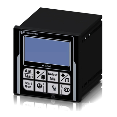
tecnoelettra TE808 VVF User manual

TE808-MOTORPUMP FIREFIGHT-V3-EN.doc rev.03 1
TE808 VVF
Motorpump
Instructions manual (release.V3)
PREFACE
Thanking you for preference, TECNOELETTRA SRL hopes that the use of this equipment will satisfy
your needs.
This manual is made to help and assist the technician to program the unit correctly for different
installations and connections.
In order to ensure efficient operation and durability, it is recommended the strict observance of the
rules described here.
Thanks in advance for your suggestions that will contribute to possible further improvements of the
equipment.
For any question always consult the TECNOELETTRA Technical Department.
TECNOELETTRA S.r.l.
Note:
The manufacturer reserves the right to modify the equipment for any manufacturing or commercial
needs, without the obligation to promptly update this installation and using manual.

TE808-MOTORPUMP FIREFIGHT-V3-EN.doc rev.03 2
IND
EX
Section 1 – General requirements and installation
1- 1 Introduction ....................................................................................................................................................5
1- 1.1 General rules...........................................................................................................................................5
1- 2 General norm of security................................................................................................................................6
1- 2.1 User responsability..................................................................................................................................6
1- 2.2 Safety first of all.......................................................................................................................................6
1- 2.3 Importance of the manual........................................................................................................................6
1- 2.4 Note legend.............................................................................................................................................7
1- 2.5 Electrical systemprotections...................................................................................................................7
1- 2.6 Controls..................................................................................................................................................7
1- 2.7 Staff training............................................................................................................................................7
1- 2.8 Cleaning..................................................................................................................................................7
1- 2.9 Operators................................................................................................................................................7
1- 2.10 Residual risks........................................................................................................................................7
1- 3 Homologation/certifications...........................................................................................................................8
1- 4 Waste and residual management...................................................................................................................8
1- 5 Disposal/Scrapping........................................................................................................................................9
1- 6.1 Equipment disposal.................................................................................................................................9
1- 6.2 Materials that make the equipment..........................................................................................................9
1- 6.3 Consumer products.................................................................................................................................9
1- 6.4 Separate collection and start recovery.....................................................................................................9
1- 6.5 How about dismantling the equipment .....................................................................................................9
1- 6 Rating plate...................................................................................................................................................10
1- 7.1 Equipment Identification........................................................................................................................10
1- 7 Maintenance..................................................................................................................................................11
1- 8.1 Internal battery replacement ..................................................................................................................11
1- 8.2 Clean....................................................................................................................................................11
1- 8 Technical specifications ..............................................................................................................................12
1- 9 Storage..........................................................................................................................................................13
1- 10 Unpacking...................................................................................................................................................13
1- 11 Installation ..................................................................................................................................................13
1- 12 USB Description.........................................................................................................................................14
1- 13 Warranty......................................................................................................................................................14
1- 14 Electrical connections................................................................................................................................15
1- 15 Functioning modes.....................................................................................................................................16
1- 15.1 Automatic............................................................................................................................................16
1- 15.2 Manual................................................................................................................................................16
1- 15.3 Reset..................................................................................................................................................16
1- 15.4 Alarms.................................................................................................................................................16
1- 16 Display pages .............................................................................................................................................17
1- 16.1 Main page description.........................................................................................................................18
1- 16.2 Batteries control..................................................................................................................................19
1- 16.3 Engine instruments..............................................................................................................................20
1- 17 General description of the equipment.......................................................................................................21
1- 17.1 Alarms informations page....................................................................................................................22
1- 17.2 Events list............................................................................................................................................22
1- 17.3 Keyboard description...........................................................................................................................23
1- 17.4 Controller informations page................................................................................................................23
1- 17.5 Technical informations page................................................................................................................24
1- 18 Accessories................................................................................................................................................25

TE808-MOTORPUMP FIREFIGHT-V3-EN.doc rev.03 3
Section 2
–
Navigation
2- 1 Navigation menu...........................................................................................................................................27
2- 2 Navigation diagram ......................................................................................................................................28
2- 3 Navigation instructions................................................................................................................................29
2- 4 General setup description............................................................................................................................30
2- 4.1 Display setup.........................................................................................................................................31
2- 4.2 Clocksetup...........................................................................................................................................32
2- 4.3 Security setup .......................................................................................................................................33
2- 4.4 IO Monitor .............................................................................................................................................34
2- 4.5 Alarms setup .........................................................................................................................................35
2- 4.6 Connectivity ..........................................................................................................................................39
2- 5 Engine setup description.............................................................................................................................41
2- 5.1 Starting setup........................................................................................................................................ 42
2- 5.2 Stop setup ............................................................................................................................................44
2- 5.3 Preheat setup .......................................................................................................................................45
2- 5.4 Temperature setup.................................................................................................................................46
2- 5.5 Oil setup ...............................................................................................................................................48
2- 5.6 Warranty setup......................................................................................................................................50
2- 6 UNI12845 setup description.........................................................................................................................51
2- 6.1 Pump setup ...........................................................................................................................................52
2- 6.2 Fuel setup..............................................................................................................................................53
2- 6.3 Autonomy setup.....................................................................................................................................54
2- 6.4 Service setup.........................................................................................................................................55
2- 6.5 Batteries setup.......................................................................................................................................56
2- 7 Trials setup...................................................................................................................................................57
2- 7.1 Weekly trials..........................................................................................................................................57
2- 7.2 Monthly trials .........................................................................................................................................58
2- 7.3 Quarterly trials.......................................................................................................................................58
2- 7.4 Weekly trials description page................................................................................................................59
2- 7.5 Monthly trials description page...............................................................................................................59
2- 7.6 Quarterly trials description page.............................................................................................................60
Section 3 – Remote control
3- 1 GSM preliminary connections instructions.................................................................................................62
3- 1.1 Serial cable...........................................................................................................................................62
3- 1.2 Antenna connection...............................................................................................................................62
3- 1.3 Power connection..................................................................................................................................62
3- 1.4 SIMcard settings...................................................................................................................................63
3- 1.5 LED diagnosis.......................................................................................................................................63
3- 1.6 On board settings..................................................................................................................................63
3- 2 SMS command and control..........................................................................................................................64
3- 2.1 SMS commands....................................................................................................................................64
3- 3 Remote control software..............................................................................................................................65
Section 4 – Download
4- 1 Firmware and project installation instructions ...........................................................................................72
4- 1.1 Firmware update ...................................................................................................................................72
4- 1.2 Project update.......................................................................................................................................74

TE808-MOTORPUMP FIREFIGHT-V3-EN.doc rev.03 4
S
S
Se
e
ec
c
ct
t
ti
i
io
o
on
n
n
1
1
1
–
–
–
G
G
Ge
e
en
n
ne
e
er
r
ra
a
al
l
l
r
r
re
e
eq
q
qu
u
ui
i
ir
r
re
e
em
m
me
e
en
n
nt
t
ts
s
s
a
a
an
n
nd
d
d
i
i
i
n
n
n
s
s
s
t
t
t
a
a
a
l
l
l
l
l
l
a
a
a
t
t
t
i
i
i
o
o
o
n
n
n

TE808-MOTORPUMP FIREFIGHT-V3-EN.doc rev.03 5
1
-
1
Introdu
ction
- TECNOELETTRA SRL thanks you for your confidence
and remind you that this unit is the result of continuous
research on improving the product that our engineers are
constantly pursuing, thanks to the proven expertise and
huge experience in this area.
- The purpose of this manual is to aid the proper
installation and right use of the device.
- Reading this publication and understanding the
commands and programming the parameters before
operations start-up and use.
- TECNOELETTRA SRL can not guarantee that the
translations are fully in accordance with the direction of
the Italian text, so for any inconsistency prevail manual
written in Italian.
- In order to provide a more accurate and appropriate
support, users are invited to notify the Customer Service
Office of TECNOELETTRA any suggestions, note or
comment on this manual.
- The Customer Service is available to help resolve
concerns or situations whose solution is not clear in this
publication.
-
This publication is part of the equipment and must be
kept in an easily accessible location away from agents
that may deteriorate the state, in a perfect state of
maintenance and disposal of those who expressly
requests it, provided that the applicant is in some way
related to the operation of the equipment.
In case some parts of it were no longer legible, if you
need a new copy of our documentation please contact
our Customer Service Office.
The controller TE808 was designed for easy installation
and use by the installer and the operator of the
generator, thus avoiding the recourse of a continous and
tedious consultation of the operating manual . In many
situations, such as setting parameters set-up, data
display, alarm conditions, etc.., an indication in the Help
display indicates to press the HELP button for a help
message. This manual thus contains only the information
necessary to introduce the operator at the use of TE808
controller.
1
-
1.1 General rules
WARNING!
The equipment can not be used for other
purposes without the express authorization
or any changes made by TECNOELETTRA
SRL.
For best results, TECNOELETTRA SRL recommends
that all operations carried out at regular cleaning to keep
the switchgear at its best.
1- 1.1.1 Responsability
•TECNOELETTRA SRL disclaims any liability for
damage or injury resulting from use not covered in
this manual, improper use of equipment, as well as
the use of unqualified personnel or the use of non-
original spare parts.
•User
User is responsible for damage to people or property
resulting from:
- imporper or different use from those indicated in this
manual;
- compliance with the requirements of safe use and
safety norms;
- modifications to the equipment;
- use of non-original of unfit spare parts.
•Manufacturer
The manufacturer is the company that physically
performs the assembly, testing directly or by his
authorized representative of the equipment and is
ultimately responsible.
The manufacturer is responsible for the efficiency of the
equipment.
In particolar the manufacture is responsible for :
- parts used for assembly;
- compliance with legislation in the country of use of
equipment, if the buyer had informed the
manufacturer of the equipment on the laws in force.

TE808-MOTORPUMP FIREFIGHT-V3-EN.doc rev.03 6
1
-
2
General norms of sec
urity
WARNING!
Do not install or operate your TECNOELETTRA
equipment, until you have read these safety
norms.
1- 2.1 User responsability
The basic safety rules established in this chapter is a guide
for the installation and safe operation of TECNOELETTRA
equipment.
These general safety rules, with other chapters on
installation, operation and cleaning up constitue the
complete instruction manual.
All staff involved with this equipment for any reason, must
be familiar with this information before you start.
It is responsability of the Buyer be sure that the procedures
are followed, and if required any change in use, appropriate
procedures should be set to continue with the activities of
security equipment.
It is strongly advised to contact TECNOELETTRA to be sure
that the equipment can be converted to new use and to
continue to operate safely.
If the equipment is not purchased directly from
Tecnoelettrica or its representatives, is Buyer's
responsability to ensure that equipment conforms to current
safety standards.Buyer is strongly advised to contact
TECNOELETTRA to ensure that the equipment operates
safely.
1- 2.2 Safety first of all
TECNOELETTRA equipment is designed and produced with
due consideration and attention to safety rules.
In any case, the presence of security systems does not
exempt operators from acting with caution: the non-
compliance can lead to accidents and damage the
components of equipment. For your protection and
protection of others, learn and always follow safety rules set
forth in this chapter.
Develop safe work habits by reading the rules and stick to
them. Keep this paper handy and look through from time to
time to refresh your understanding of the norms.
1- 2.3 Importance of the Manual
•Information about the manual
We hope that the information contained in this manual will
be of help.
They will give an explanation of the correct and secure use
of your equipment and are based on data and our current
and best knowledge.
Carefully read the manual, including recommendations and
suggestions, and the conditions of sale and warranty.
•
TECNOELETTRA wrote this book with the greatest
care, trying to make it as complete and clear as
possible. However, if some point proves to be
incomplete or unclear, contact us without hesitation.
•Importance of the manual
This instruction manual was born to help you in the
correct installation, starting-up, use and cleaning of your
equipment.
This manual is integral part of equipment in order to
obtain the best performance and it should be kept for the
duration of the product.
Therefore, please do not remove, tear, or write to parts of
the manual, taking care to integrate with any updates
provided by TECNOELETTRA.
Please keep this manual in a place protected from
moisture and heat, accessible and known to all operators
(photocopy any parts of interest to the consultation of the
various operators).
In case of sale or transfer of the machine (on which the
equipment is installed) to another user, these instructions
must be delivered to the new user.
•This manual is to explain:
- the use of equipment, according to software and project;
- technical features;
- compostition of the different parts;
- operations for installation and assembly;
- operations of starting-up and programming, etc..;
- the risks related to hazardous waste, measures to
eliminate it and instructions to operate safely;
-cleaning;
- Recommended spare parts for the stock.
Any person appointed by customer to carry
out the installation, start-up and repair of this
equipment must be aware of the contents of
this Manual, with particular reference to safety
standards. If the involved person does not
understand the language of the manual, the
client must properly educated him.
This manual provides guidance and instructions on
equipment that will be installed, but it is not intend to
replace, supplement or modify any general or specific
NORM, RULE, DECRETE or LAW, in the place where the
installation takes place and concerning the safety and use
of electrical equipment.
TECNOELETTRA, unless otherwise specified, can
provide a copy of this manual equipment in the original
language of the country of use.
The copy of the manual is included on the CDrom inside
the packaging of the equipment and should be used for
the installation, assembly, calibration, setup, startup,
etc…

TE808-MOTORPUMP FIREFIGHT-V3-EN.doc rev.03 7
After installing this copy mus
t be retained for all future
interventions.
TECNOELETTRA can provide duplicates of the manuals
supplied with the equipment if customer request.
Requests must be submitted to our Technical Department
together with the equipment information found on the CE
label applied on the top of plastic enclosure of the
equipment.
The manual, technical documentation and drawings
delivered together with the tools are proprietary of
TECNOELETTRA, who reserves all the rights, and it can not
be made available to third party without authorization.
TECNOELETTRA will be glad to consider and possibly
accept suggestions for improvement of this manual.
Suggestions should be submitted to our Technical
Department.
Upon handover the equipment to other, the user also agrees
to deliver copies of the manual in his possession and at the
same time to report the fact to TECNOELETTRA.
1- 2.4 Legend of the note
The text should draw attention, will be highlighted along
these graphics settings:
DANGER!
Follow text describing danger situation
NOTE!
Follow text describing note for the reader.
NOTICE!
Follow text describing the notice.
WARNING!
Follow texts nedded attention.
These simple graphical labels are used to indicate the
operator situations, actions, informations, special operations
that may cause damage to people and to equipment, or
suggest a correct operating procedure.
1- 2.5 Protections of the electrical system
The electrical system of the equipment was designed and
constructed to protect operators from electrical shock and
possible overheating or other abnormal dangerous
conditions . All electrical parts which could be in contact
with operators, should be waterproof to penetration of
liquids or vapors that could cause short circuits or
deterioration of insulation. Then there must be used an
overcurrent protection to prevent overheating or
malfunctions that may cause hazardous conditions.
1
-
2.6 Controls
•Before start-up
- Ensure that all security systems and protections are
installed and operative.
•During operation
- Do not start this equipment until you have read and
understood the operating instructions and after you have
got used to the equipment and its controls.
- Be careful and observe lights and warning signs
displayed on the equipment.
- Do not operate damaged or defective equipment.
•After the power off
- Make sure the power sources are off.
1- 2.7 Staff training
All staff using the equipment must have undergone a
training operation course that includes:
- readingandcomprehensionof this InstructionManual
- a practical instruction by TECNOELETTRA staff to start-
up the equipment is available under request,
TECNOELETTRA can give a training course of
product’s operation to customer staff. The training
course is not free.
1- 2.8 Cleaning
•Procedure manual cleaning
- Do not use toxic solvents and / or flammable to clean the
equipment.
- Turn off the electricity (close) before cleaning the
equipment.
- Keep closed electrical panel protections when you are
cleaning the equipment.
- Always clean the seals around the equipment as soon
as possible.
- Never attempt to clean the equipment while it is running.
1- 2.9 Operators
The equipment described here requires only one operator
to start and control the functioning.For special settings
and use may be also required the intervention of a second
operator.
1- 2.10 Residual risks
•Risks linked to electrical energy
All electric units are supplied with electricity and therefore
are dangerous.
All panels and electrical panels and junction boxes must
be properly closed.
Cables must not be damaged or left hanging, but must be
properly trimmed and tied.
Operations on the electrical system should only be
performed by qualified personnel, with power
disconnected. To avoid unwanted connections, the main
switch must be disconnected and properly locked.

TE808-MOTORPUMP FIREFIGHT-V3-EN.doc rev.03 8
1
-
3
Homologations/certifications
The equipment described in this manual complies with
homologations / certifications below:
•EMC: 2004/108/CE
•EN61000-6-3 (2007)
•EN61000-6-2 (2005)
Halt test Accelerated Reliability Test Centers
1- 4 Waste and residual management
General information on how to manage waste.
Identify and classify wastes according to specifications
provided by law in the country of use.Do not leave or collect
waste in an uncontrolled way. Do not enter into surface
water or groundwater.
Do not mix different types of waste.
Deliver the waste to authorized people by the competent
authorities in the country for collecting, transporting and
processing of waste.
Prepare documentation required by administrative
regulations in force in the country of use (production
register, storage and disposal, docuemnts of transport).
Administrative duties (record keeping, preparation of
documents etc...).
1)
Waste separation by homogeneous types.
The waste must be collected and stored for
"homogenous types", since this is the only system
through which you can:
- avoid any risk of incompatibility in terms of chemical
and physical characteristics of waste products.
- ensure final proper treatment turning into a more
useful and less dangerous, allowing their eventual
recovery.
It is therefore important not to mix different types of
wastes.
2) Use appropriate containers for handling and storage.
Vessels designed to contain wastes must have
adequate strength requirements in relation to chemical
and physical properties and characteristics of the
hazardous waste contained.
3) Vessels label
In order to disclose, during storage in the company, the
nature and hazardous of the waste, the containers
must be appropriately marked with labels or lables
affixed on the containers themselves or placed in
storage areas. In particular it is important that waste
containers are identified with a description of the type
of waste and hazardous to humans and the
environment.
4) Waste handling in the company.
During handling, ensure that containers are closed
properly.Avoid locations where there are wells of water
stored to avoid accidental spills into public sewer and
white water .
5) Storage of solid waste heaps.
- In order to avoid possible pollution of soil, if storage
takes place in piles, they should not be made on
open ground but on strong bases (such land paved)
- The waste stored in piles must be protected from the
rain water where their runoff could lead to pollution of
the water itself.

TE808-MOTORPUMP FIREFIGHT-V3-EN.doc rev.03 9
1
-
5
Disposal/Scrapping
1- 5.1 Machine disposal
Dismantling operations must be performed by qualified
personnel and in compliance with all applicable laws.
At the end of real life, the user company should proceed to
the alienation equipment in accordance with the in force
regulations by providing the first general cleaning of various
elements and after the separation of the parts making up the
equipment.After removing the equipment is necessary to
separate the various materials in accordance with the law
requires the country where the equipment should be
discarded. The device contains no hazardous substances or
requiring special removal procedures.
1- 5.2 Materials used on the equipment
Regarding the elimination should be noted that the materials
used on the equipment are not of hazardous nature, and are
essentially:
- polyethylene plastic;
- electric cables with relative sheaths;
- monitoring and implementing electronic devices.
During the disposal process will need to comply to the
regulations in the country of use.
1- 5.3 Consumer products
Regarding the disposal of consumer products, observe the
following rules:
•Batteries
The battery of the equipment must be replaced by a
maintenance electrician.
Used batteries should not be disposed as common waste,
but it shall be delivered to designated disposal sites.
1- 5.4 Separate collection and recovery start
The unit consists of material that can easily be recycled and
used as raw material for other production
processes.Through proper recycling can recover a wide
range of waste with ecological and economic advantages.
•Plastic materials
Plastic parts can be retrieved for the production of new
resources both by recycling in the origin area and the heat
and energy production through their incineration, thus
avoiding, at the end of the life cycle, they become a burden
on the environment under form of waste to be disposed of in
landfills.To make a better recovery of such material is
necessary to collect differentiating types.
1
-
5.5
About dismantling the equipment
Before starting the decommissioning of the equipment,
verify the current legislation in force specially:
-registration requirements and / or communication to
control organisms;
- arrangements for environmental protection;
- requirements for the scrapping;
- requirements about health and safety safeguard of
workers
About disposal of the equipment, follow this procedure:
1) disconnect the equipment from the mains;
2) disassemble the apparatus collecting separately the
different components in relation to their nature as
indicated in the paragrapgh "Separate collection and
start recovery";
3) proceed to the storage and disposal of waste and
materials for reuse as indicated in this paragraph and
the regulatory requirements set out in the country of
use.

TE808-MOTORPUMP FIREFIGHT-V3-EN.doc rev.03 10
DE
0000
FW
000
SW
0000
1
-
6
Product label and rating plate
1- 6.1 Equipment identification
General identifications of each unit are traced on the plate below and placed on the controller.
NOTE!
Inform the maufacturer the general identification data reported on the label,
before asking for technical specifications or information about the equipment.
Fw
.x.x.x.x
Sw.x.x.x.xx.xxx
Sn.xx.xxxxxx
Fw
-
firmware
Sw-software
Sn-serial number

TE808-MOTORPUMP FIREFIGHT-V3-EN.doc rev.03 11
Battery type Voltage
CR2032 3 V
1
-
7
Maintenance
1- 7.1 Internal battery replacement
1) Remove the screws (item 1) on the back of
enclosure;
2) Separate the back cover from the front panel
(Item 2);
3) Remove lower board from its slot (pos. 3);
4) Remove and replace internal battery (pos. 4)
with an equal one.
1
-
7.2
Cleaning
If necessary, clean with soft cloth.
Do not use any cleaner

TE808-MOTORPUMP FIREFIGHT-V3-EN.doc rev.03 12
1
-
8
Technical data
GENERAL DATA In parenthesisvalues at 24V
Battery rated voltage
12Vdc or 24Vdc
Voltage range
from 7Vdc to 33Vdc
BOARD displayLGC-2107TE808D
Fixed consumption 12Vdc (24Vdc) 150 mA(75 mA)
Relay consumption 12Vdc (24Vdc) 210 mA(95 mA)
Backlight consumption 12Vdc (24Vdc) 100 mA(50 mA)
Pre-excitation consumption 12Vdc (24Vdc) 130 mA(170 mA)
Heater consumption -
Digital input closed to negative consumption 12Vdc (24Vdc)
40 mA (20 mA)
Maximum consumption 12Vdc (24Vdc) 630 mA(410 mA)
-40 °C + 70 °C (electronic)
-20 °C + 70 °C (display)
-30 °C + 70 °C (with heater)
CAMPO DI TEMPERATURA
-40 °C + 80 °C (stocking)
DISPLAY LGC-2107TE808D LCDmonocromatic 5,7" , 320x240 pixel, transflective, white LEDs backlight
USB PORT "Device" type, full-speed for upload firmware and projects, connector "A" female
DIGITAL INPUTS
Input type Active at low level with pull-up
Input current < 10 mA
Low voltage level < 3.5 V
High voltage level > 8,0 V
Input latency interruption < 30 ms
SPEED INPUT "W"
Input type In AC, frequency and voltage measures
Range of voltage From 6 to 100 Vpp (precision 10%)
Range of frequency From 40 Hz to 2000 Hz (precision 2%)
ALTERNATOR PRE-EXCITATION INPUT/OUTPUT (D+)
Input type Voltage measure + pre-excitation current generation
Range of voltage From 0 to 40 Vdc
Input current < 15 mA
Pre-excitation current 130 mAa 24 V - 170 mAa 12 V
RELAYS OUTPUT
Type of contact N.O. contacts with one common pole
Rated current 5 A / 30 VDC - 5 A / 250 VAC
SENSORS INPUTS
Input type 3 inputs for resistancemeasures referred to the board negative
Range of measure
- fuel level from 0 to 850 ohm
- engine temperature from 0 to 1300 ohm
- oil pressure from 0 to 400 ohm
Measurecurrent
- fuel level < 10 mA
- engine temperature < 6 mA
- oil pressure < 20 mA
Precision < 5 %
SERIAL PORTS
Type Serial RS -232 wihtout handshake signals
Cable lenght < 3 m
Speed Up to 115200 bps
ANALOG OUTPUTS
Type Insulated voltage referred to the board negative
Output current 1 mA max
Regulation range from 0 to 5 V
INGRESSI DI CORRENTE DI CARICO
Range of measure 0.05 ÷ 6A
Maximum overcurrent 30 A
Type of measure RMS calculated value at 2 KHz and a 12 bit converter
Precision < 0.5 % end of scale.
VOLTAGE INPUTS
Type of input Voltmetric transformers
Rated voltage 230 Vac (L-N) - 400 Vac (L-L)
Range of measure from 0 to 350 Vac (L-N) - from 0 to 600 Vac (L-L)
Range of frequency from 25 Hz to 80 Hz
Precision < 0.2% F.S.
Type of measure RMS calculated value at 2 KHz and a 12 bit converter

TE808-MOTORPUMP FIREFIGHT-V3-EN.doc rev.03 13
1
-
9
Storage
In the case of prolonged storage leave your device away
from rain and wind and possibly dry ambient. It is not
advisable to cover the equipment with waterproof film that
will prevent the evaporation of any moisture. The moisture
can cause corrosion on the metal parts and damage the
electronic components.
The characteristics of storage must be within the limits
prescribed below:
Temperature……………….………..…….. -40 ÷ 80 °C
Relative Humidity………...………….……….. 30 - 95%
Atmospheric pressure….……. 860 - 1060 hPa (mbar)
1
-
10
Unpacking
The equipment comes in a cardboard box.
Check the package contents to be submitted:
- TE808;
- CD - ROM;
- Instruction Manual;
- Terminals;
- Gasket;
- Warranty;
If even one of the objects described above are missing,
please contact Tecnoelettrica Srl
After unpacking, check that the equipment and check that
there are no damaged parts. If in doubt, do not install the
equipment and contact immediately Tecnoelettra Srl
Packaging materials (plastic bags, cardboard, etc. ...)
should be kept away or send to disposal area to be
eliminated, see. par.1.6.
1
-
11
Installation
Drill a hole for the rectangular box TE808 and No. 6 holes
Ø3 mmon the mounting surface, as indicated on the
template (A). Use the screws (1) supplied. If needed buy
only screws with the same characteristics.
Make sure the gasket (2) is mounted correctly and perfectly
fits the perimeter of the box TE808 (3).

TE808-MOTORPUMP FIREFIGHT-V3-EN.doc rev.03 14
1
-
12
USB connection description
Via PC connection is possible:
- Transferring the new firmware or software updated to the controller;
- Download data from the controller to analyze them in charts and/or tables or print them directly.
The USB cable (1) used is of type double AA male: Cable code 1571807F.
3
2
4
1
1. USB cable (type “A-male / A-male”);
2. Mounting hole to close the rubber cap using a screw;
3. USB port: normally closed to prevent the weather can be enabled from the keyboard;
4. Closure and rubber protection, IP65.
1
-
13 Warranty
TECHNICAL SUPPORT
•For more informations and technical support, please send an e-mail to: te808@tecnoelettra.it
WARRANTY
•2 years warranty from the real installation date.

TE808-MOTORPUMP FIREFIGHT-V3-EN.doc rev.03 15
1
-
14
Electrical connections
J1
RS232
J2
J3
J4
J5
J6
J1
-
Vdc
supply
1-battery positive
2-battery negative
J2
-
Analog inputs
1-D+ batterycharger alternator
2-Tachometric signal (W;Pickup)
3-not used
4-engine temperature instrument
5-fuel instrument
6-oil pressure instrument
J3
-
Digital inputs
1-Reset buzzer
2-External lamp test
3-Remote start
4-Auxiliary starting button
5-Start pressure switches
6-Low fuel level
7-Low oil pressure
8-High engine temperature
J4
-
Relay outputs 5A
1-Preheating
2-EV/EM
3-Acoustic buzzer
4-Global alarm
5-Auxiliary starting output
6-Relays common
J8
-
Dry contact outputs
1-Start battery 1
2-Start battery 1
3-Not used
4-Start battery 2
5-Start battery 2
6-Not used
J9
-
Relay outputs 5A
1-Global alarm
2-Pump working
3-Start failed
4-Not automatic
5-Not used
6-Relay common
7-Not used
J10
-
Vac m
a
ins voltages
1-neutral
2-L3
3-L2
4-L1
RS232
-
communication ports
RS232a- default setting for PC
communication
RS232b- default setting for GSM
modem connection
J7
J8
J9
J10
J5
-
Mains presence input
J6
-
Analog and digital inputs
1-Water pressure transducer
2-Oil temperature instrument
3-gnd
4-Batterycharger n.1 alarm
5-Batterycharger n.2 alarm
6-gnd
J7
-
DC measures inputs
1-gnd
2-Battery voltage 2
3-Battery current 2 (out)
4-Battery current 2 (in)
5-Battery voltage 1
6-Battery current 2 (out)
7-Battery current 2 (in)

TE808-MOTORPUMP FIREFIGHT-V3-EN.doc rev.03 16
4
5
1
2
1
-
1
5
Fu
nctioning mod
es
To scroll the operative modes (1, 2 and 3) use the
arrows (4, 5) of the drive and confirm the selected
modality pressing the “i” button (6).
1
-
1
5.1
Of
f
Mode OFF/RESET- The engine cannot be started.
Selecting this modality, the engine is immediately
stopped and eventual alarms are reset. The alarm is
not reset if the cause of the alarm is still present.
1
-
1
5.4
Al
arm
s
When an alarmappears, the display shows its
description. In case of multiple alarms, they are
shown individually in sequence. For every alarm it’s
available a help message to detect the possible
cause of the problem.
The reset of the alarms can be made pressing the
RESET button.
If the alarmis not reset and remains on display, it
means that the cause of the alarm has not been
removed.
1
-
1
5.2
Automatic
Mode AUT – The engine starts automatically if the
pressure switches are open because a fire is
detected. The START button is inhibited in this
modality.
1
-
1
5.3
Manual
Mode MAN – The engine can be started or stopped
manually with the START and STOP buttons.
3

TE808-MOTORPUMP FIREFIGHT-V3-EN.doc rev.03 17
POS. NAME DESCRIPTION
1 Work hours It shows the total working hours of the engine
2 Hours left to service It indicates the number of hours left to the next service
3 State of battery 1 Voltage and current of the battery 1
4 State of battery 2 Voltage and current of the battery 2
5 Automatic test clock Symbol that appears if an automatic test is programmed
6 Date and time Actual date and time
7 Environmental temperature Value of the environmental temperature
8 Functioning mode It shows the selected functioning mode
9 Fuel level Level of the remaining fuel in %.
10 Autonomy
It shows the hours of automomy. It depends by the actual fuel
level and the set consumption
11 D+ It shows the D+ voltage
12 Engine temperature It indicates the engine temperature
13 Oil pressure It shows the oil pressure value
1
-
1
6 Display pages
2
3
4
5
6
7
8
9
10
11
12
1

TE808-MOTORPUMP FIREFIGHT-V3-EN.doc rev.03 18
1
-
16.1
Main page description
1
2
3
4
5
6
7
8
9
10
11
12
13
14
15
16
POS. NAME DESCRIPTION
1 RPM
It shows the RPM value.
To calibrate it, start the motorpump at the nominal
RPM value, and select this instrument with the arrows of the navigation
drive. Then confirm with “i”. The actual value will b
e updated to the nominal
RPM value.
2 “Mains lacking” icon It appears if the input J5 doesn’t detect the mains presence
3 “Service” icon It appears when the service hours are expired
4 “Preheat” icon It appears during the preheating at the starting
5 Engine animation Animation ti show if the engine is running
6 “Stop” icon It appears during the stopping of the engine
7 “Start” icon It appears during the starting phase of the engine
8 “Aux” icon It appears when the auxiliary start output is activated
9 “Weekly test” icon It appears if a weekly test is programmed
10 “Monthly test” icon It appears if a monthly test is programmed
11 “Quarterly test” It appears if a quarterly test is programmed
12 “Hand” icon It appears if is enabled the function of start and stop by programmable levels
of the water pressure.
13 “UNI10779” icon It appears if the stop by the norm10779 is enabled
14 Water pressure of the system
It shows the water pressure measured by the controller
15 Indicatore start remoto When at least one of the pressure switches is open, a flame is shown to
indicate that a start request has been detected
16 Generic alarm message It’s shown if an alarm is present
17 Batterycharger state The battery icon becomes black if an alarm about the batterycharger is
present
17

TE808-MOTORPUMP FIREFIGHT-V3-EN.doc rev.03 19
1- 16.2 Batteries control
1
2
6
3
5
POS. NAME DESCRIPTION
1 Charge current Charge current of the battery
2 State of the batterychargers ON if tha battery charger is working correctly, OFF if the battery
charger is in alarm
3 Start indication on the battery It indicates if the battery is used at the starting. The 2 batteries are
used alternatively at every starting
4 Battery voltage It indicates the actual battery voltage
5 Level indicatior of the battery charge
Bar graph to indicate the charge level of the battery
6 Minimum and maximum voltage alarm
thresholds It shows the minimum and maximum levels of the battery. Over
these limits, an alarm is shown
4

TE808-MOTORPUMP FIREFIGHT-V3-EN.doc rev.03 20
1- 16.3 Engine instruments
POS. NAME DESCRIPTION
1 Engine animation Animation to show if the engine is running or not
2 RPM calibration Button that has to be pressed (with “i” button) to set the actual
RPM value to the nominal value
3 Warranty hours It indicates the hours left to the warranty expiry
4 RPM Graph to show the RPM value
5 Oil temperature It indicates the oil temperature
6 Engine temperature It indicates the engine temperature
7 Oil pressure It indicates the oil pressure
8 Battery charger alternator voltage It shows the D+ voltage
9 Test pressure It indicates the pressure detected during the test
3
1
4
5
6
7
8
9
2
Table of contents
Other tecnoelettra Controllers manuals
Popular Controllers manuals by other brands
Federal Signal Corporation
Federal Signal Corporation UltraVoice Installation, operation and service manual

Scion-Tech
Scion-Tech SC08.CTL200 user manual

Chargery
Chargery BMS16T Series manual

Isimet
Isimet LA Series Installation, Operations, Start-up and Maintenance Instructions

Netafim
Netafim nmc-pro installation guide

Orton
Orton AutoFire AF4TS user guide
