J-141
Dual PID Control
SENSORS
CONTROLLERS
MOTION DEVICES
SOFTWARE
(J)
Temperature
Controllers
(K)
SSRs
(L)
Power
Controllers
(M)
Counters
(N)
Timers
(O)
Digital
Panel Meters
(P)
Indicators
(Q)
Converters
(R)
Digital
Display Units
(S)
Sensor
Controllers
(T)
Switching
Mode Power
Supplies
(U)
Recorders
(V)
HMIs
(W)
Panel PC
(X)
Field Network
Devices
Specifications
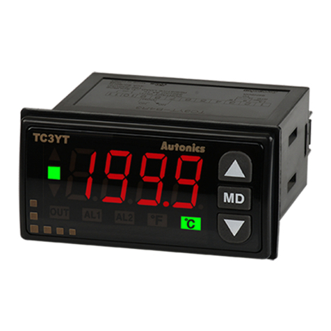
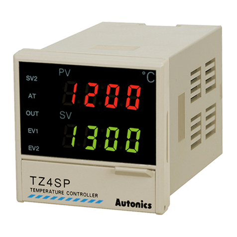
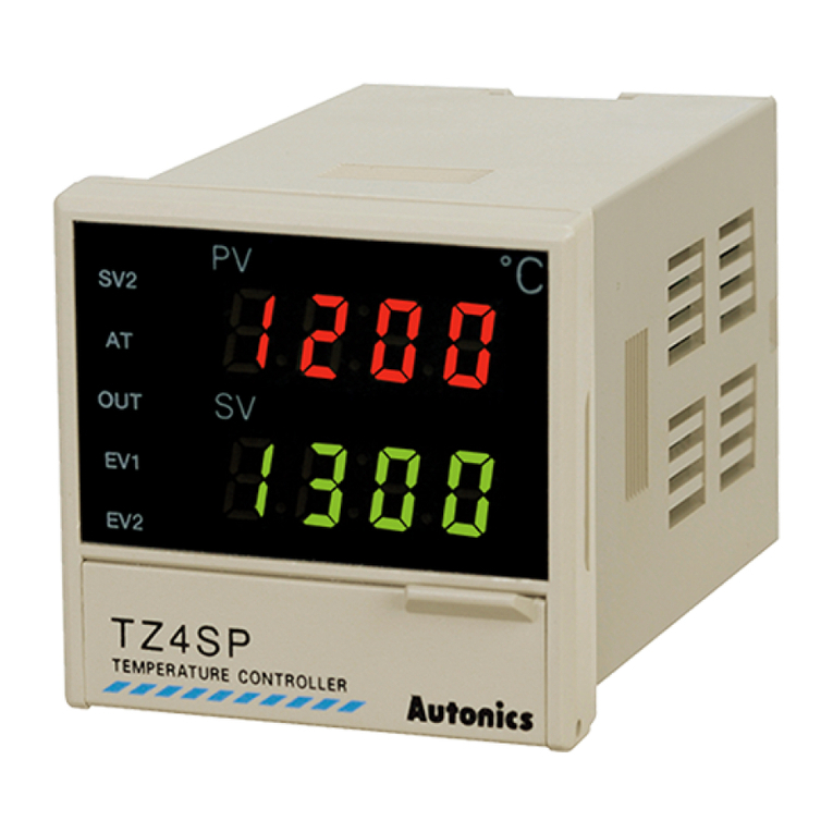
Series TZ4SP
TZN4S TZ4ST TZ4M
TZN4M
TZ4W
TZN4W
TZ4H
TZN4H
TZ4L
TZN4L
Power supply 100-240VACᜠ50/60Hz
Allowable voltage range 90 to 110% of rated power voltage
Power consumption Max. 5VA (100-240VACᜠ50/60Hz) Max. 6VA (100-240VACᜠ50/60Hz)
Display method 7-segment LED (PV: red, SV: green)
Character size
(W×H)
PV
TZ4SP:
4.8×7.8mm
TZN4S:
7.8×11.0mm 4.8×7.8mm
TZ4M:
9.8×14.2mm
TZN4M:
8.0×13.0mm 8.0×10.0mm
TZ4H:
3.8×7.6mm
TZN4H:
7.8×11.0mm
9.8×14.2mm
SV
TZ4SP:
4.8×7.8mm
TZN4S:
5.8×8.0mm
TZ4M:
8.0×10.0mm
TZN4M:
5.0×9.0mm
TZ4H:
3.8×7.6mm
TZN4H:
5.8×8.0mm
8.0×10.0mm
Input
type
RTD DPt100Ω, JPt100Ω, 3-wire (allowed resistance: max. 5Ω per line)
TC K(CA), J(IC), R(PR), E(CR), T(CC), S(PR), N(NN), W(TT) (allowed resistance: max. 100Ω per line)
Analog 1-5VDCᜡ, 0-10VDCᜡ, DC4-20mA
Display accuracy F.S. ±0.3% or 3℃, greater value
Control
output
Relay 250VACᜠ 3A, 30VDCᜡ 3A, 1c
SSR Max. 12VDCᜡ ±3V 30mA
Current DC4-20mA (load resistance max. 600Ω)
Option
output
EVENT1 250VACᜠ1A 1a
EVENT2
-
250VACᜠ1A 1a
PV transmission
-
DC4-20mA (load resistance max. 600Ω)
Communication
-
RS485 communication
Control method ON/OFF, P, PI, PD, PIDF, PIDS control
Alarm output hysteresis 1 to 100℃(0.1 to 100.0℃) variable
Proportional band (P) 0.0 to 100.0%
Integral time (I) 0 to 3,600 sec
Derivative time (D) 0 to 3,600 sec
Control period (T) 1 to 120 sec
Sampling period 0.5 sec
LBA setting 1 to 999 sec
Ramp setting Ramp Up, Ramp Down: 1 to 99 min each
Dielectric strength 2,000VAC 50/60Hz for 1 min (between input and power terminals)
Vibration Mechanical 0.75mm amplitude at frequency 10 to 55Hz (for 1 min) in each X, Y, Z direction for 2 hours
Electrical 0.5mm amplitude at frequency 10 to 55Hz (for 1 min) in each X, Y, Z direction for 10 min
Relay
life cycle
Control output Mechanical: min. 10,000,000 operations,
Electrical: min. 100,000 operations (250VAC 3A resistance load)
Option output Mechanical: min. 20,000,000 operations,
Electrical: min. 500,000 operations (250VAC 1A resistance load)
Insulation resistance Over 100MΩ (at 500VDC megger)
Noise immunity Square shaped noise by noise simulator (pulse width 1㎲) ±2kV R-phase, S-phase
Memory retention Approx. 10 years (non-volatile semiconductor memory type)
Environ-
ment
Ambient temp. -10 to 50℃, storage: -20 to 60℃
Ambient humi. 35 to 85%RH, storage: 35 to 85%RH
Approval
Weight※1
TZ4SP:
approx. 205g
(approx. 144g)
TZN4S:
approx. 226g
(approx. 164g)
Approx. 218g
(approx. 162g)
TZ4M:
approx. 360g
(approx. 228g)
TZN4M:
approx.355g
(approx. 246g)
TZ4W:
approx. 365g
(approx. 246g)
TZN4W:
approx. 351g
(approx. 232g)
TZ4H:
approx. 365g
(approx. 246g)
TZN4H:
approx. 351g
(approx. 232g)
TZ4L:
approx. 474g
(approx. 304g)
TZN4L:
approx. 474g
(approx. 303g)
※1: The weight includes packaging. The weight in parenthesis is for unit only.
※Environment resistance is rated at no freezing or condensation.
