SAFETY
Fieldbus (XFB01) Instruction Manual 2-4
MOTO
MAN
2.5 Installation Safety
Safe installation is essential for protection of people and equipment. The
following suggestions are intended to supplement, but not replace, existing federal,
local, and state laws and regulations. Additional safety measures for personnel and
equipment may be required depending on system installation, operation, and/or
location. Installation tips are as follows:
• Be sure that only qualified personnel amiliar with national codes, local
codes, and ANSI/RIA R15.06 safety standards are permitted to install the
equipment.
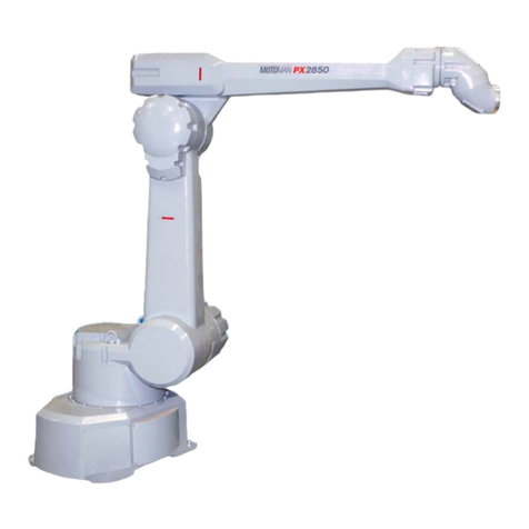
• Identify the w ork en velope of each robot with floor markings, signs, an
barriers.
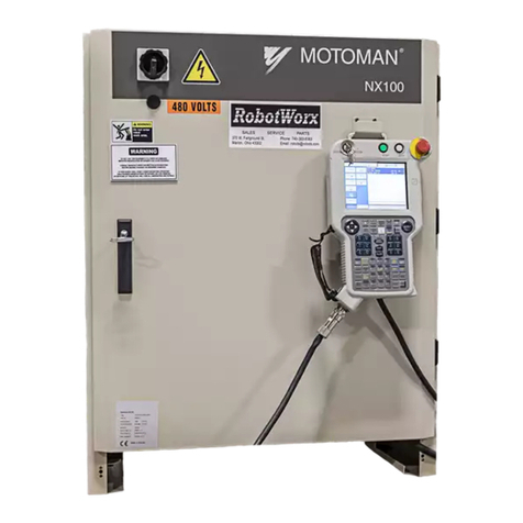
• Position all controllers outside the robot work envelope.
• Whenever possible, install safety fences to protect against unauthorized entry
into the work envelope.
• Eliminate areas where personnel might get trapped between a mo ving robot
and other equipment (pinch points).
• Provide suf ficient room inside the orkcell to permit safe teaching and
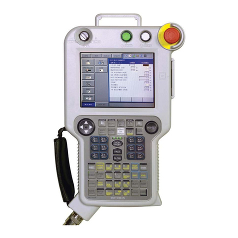
maintenance procedures.
2.6 Programming Safety
All operators, programmers, plant and tooling engineers, maintenance personnel,
supervisors, and an yone w orking near the robot must become f amiliar with the
operation of this equipment. All personnel in volved with the operation of the
equipment must understand potential dangers of operation. Programming tips are
as follows:
• Any modifications of the controller PLC can cause s vere personal injury or
death, as well as damage to the robot! Do not make any modifications to th
PLC. Making any changes without the written permission of Motoman will
VOID YOUR WARRANTY!
• Some operations require standard passw ords and some require special
passwords. Special passw ords are for Motoman use only .
YOUR
WARRANTY WILL BE VOID
if you use these special passwords.
• Back up all programs and jobs onto a flop y disk whenever program changes
are made. To avoid loss of information, programs, or jobs, a backup must
always be made before an y service procedures are done and before an y
changes are made to options, accessories, or equipment.
• The concurrent I/O (Input and Output) function allo ws the customer to
modify the internal ladder inputs and outputs for maximum robot
performance. Great care must be tak en when making these modifications
Double-check all modifications under very mode of robot operation to
ensure that you ha ve not created hazards or dangerous situations that may
damage the robot or other parts of the system.
• Improper operation can result in personal injury and/or damage to the
equipment. Only trained personnel f amiliar with the operation, manuals,
electrical design, and equipment interconnections of this robot should be
permitted to operate the system.

