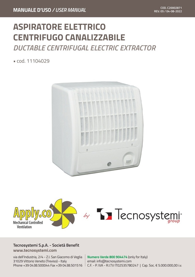
Tecnosystemi Apply.co SOTTOCAPPA 100 User manual

MANUALE D’USO
REV. 04 / 20-06-2019
ASPIRATORI ELETTRICI SERIE
EVEN-T, LUXURY, HIGH, OPEN,
CIRCLE, SOTTOCAPPA, WINDOW
Tecnosystemi S.p.A.
via dell’Industria, 2/4 - Z.I. San Giacomo di Veglia
31029 Vittorio Veneto (Treviso) - Italia
Tel +39 0438.500044 - Fax +39 0438.501516
Numero Verde 800 904474 (only for Italy)
email: [email protected]
C.F. - P. IVA - R.I.TV IT02535780247 Cap. Soc. € 5.000.000,00 i.v. www.tecnosystemi.com
Sistemi
11104028 - 11104026 - 11104012 - 11104013 - 11104014 - 11104016
11104017 - 11104018 - 11104020 - 11104021 - 11104022 - 11104024
11104000 - 11104001 - 11104002 - 11104004 - 11104005 - 11104006
11104008 - 11104009 - 11104010 - 11104040 - 11104041 - 11104042
11104030 - 11104031 - 11104032 - 11104034 - 11104035
EVEN-T LUXURY HIGH
OPEN CIRCLE & SOTTOCAPPA WINDOW
COD. C20002872

Sistemi
2
CARATTERISTICHE GENERALI
Gli aspiratori Tecnosystemi sono progettati per la ventilazione degli ambienti domestici e di locali
simili (appartamenti, ufci, negozi, garage, cucine, bagni, toilette e altre stanze) riscaldati nel
periodo invernale. Molti modelli contenuti in questo manuale possono essere utilizzati sia a
parete che a softto.
La serie può funzionare mediante interruttore di alimentazione ON/OFF oppure mediante Timer,
dove presente e, regolabile da 2 a 30 min. La serie può funzionare mediante interruttore di
alimentazione ON/OFF oppure mediante la combinazione della regolazione Timer e del sensore
di Presenza persone (regolabile da 1 a 4mt). La serie può funzionare mediante interruttore di
alimentazione ON/OFF oppure mediante la combinazione della regolazione Timer e del sensore di
Umidità (regolabile da 60% a 90%). I modelli che non prevedono alcuna regolazione, funzionano
esclusivamente mediante l’interruttore di alimentazione ON/OFF . Nella tabella di Pag. 4, sono
elencati tutti i modelli e le principali caratteristiche tecniche.
Gli aspiratori sono progettati per funzionare con tensione elettrica di alimentazione 230V 50Hz.
Il livello di rumorosità registrato ad una distanza di 3m, non supera 40 dB(A).
L’uscita nominale in termini di portata di estrazione dell’aria è:
- per ventilatori con espulsione su condotti da 100 mm: 87 - 102 m /h (± 5%)
- per ventilatori con espulsione su condotti da 125 mm: 157 -232 m /h (± 5%)
- per ventilatori con espulsione su condotti da 150 mm: 260 -348 m h (± 5%)
Gli aspiratori sono progettati per il funzionamento ad una temperatura dell’aria compresa tra 0°C
e 45°C.
La struttura degli aspiratori viene sottoposta a continui aggiornamenti e miglioramenti, per cui
alcuni modelli possono differire da quelli descritti nel presente manuale.
CARATTERISTICHE TECNICHE PRINCIPALI
CODICE MODELLO VERSIONE Ø(mm) INSTALLAZIONE
11104028 EVEN T 100 PARETE
11104026 LUXURY -- 100 PARETE / SOFFITTO
11104012 HIGH -- 100 PARETE / SOFFITTO
11104013 HIGT -- 125 PARETE / SOFFITTO
11104014 HIGT -- 150 PARETE / SOFFITTO
11104016 HIGT T 100 PARETE / SOFFITTO
11104017 HIGT T 125 PARETE / SOFFITTO
11104018 HIGT T 150 PARETE / SOFFITTO
11104020 HIGT TI 100 PARETE / SOFFITTO
11104021 HIGT TI 125 PARETE / SOFFITTO
11104022 HIGT TI 150 PARETE / SOFFITTO
11104024 HIGT TH 100 PARETE / SOFFITTO
11104000 OPEN -- 100 PARETE / SOFFITTO
11104001 OPEN -- 125 PARETE / SOFFITTO
11104002 OPEN -- 150 PARETE / SOFFITTO
11104004 OPEN T 100 PARETE / SOFFITTO
ELENCO MODELLI

3
Sistemi
11104005 OPEN T 125 PARETE / SOFFITTO
11104006 OPEN T 150 PARETE / SOFFITTO
11104008 OPEN TH 100 PARETE / SOFFITTO
11104009 OPEN TH 125 PARETE / SOFFITTO
11104010 OPEN TH 150 PARETE / SOFFITTO
11104040 CIRCLE -- 100 PARETE / SOFFITTO
11104041 CIRCLE -- 125 PARETE / SOFFITTO
11104042 CIRCLE -- 150 PARETE / SOFFITTO
11104030 SOTTOCAPPA -- 100 PARETE / SOFFITTO
11104031 SOTTOCAPPA -- 125 PARETE / SOFFITTO
11104032 SOTTOCAPPA -- 150 PARETE / SOFFITTO
11104034 WINDOWS T 125 FINESTRE / VETRATE
11104035 WINDOWS T 150 FINESTRE / VETRATE
VERSIONI
-- Accensione mediante interruttore
TPrevisto di timer (reg. da 2 a 30 min)
TI Previsto di timer (reg. da 2 a 30 min) e di sensore presenza ( da 1 a 4 mt)
TH Previsto di timer ( reg. da 2 a 30 min) e sensore di umidità (reg. da 60% a 90%)
L’Aspiratore è conforme ai requisiti delle norme e direttive EU in materia di bassa tensione e
compatibilità elettromagnetica per le apparecchiature.
Grado di protezione contro l’accesso a parti pericolose e impermeabilità:
IPX4 - modelli serie Sottocappa;
IP24 - modelli serie Luxury, High e Window;
IP34 - modelli serie Even, Open e Circle.
IMPORTANTE!
• L’installazione dell’Aspiratore elettrico dev’essere eseguita da personale qualicato e in
accordo con le norme vigenti.
• Assicurarsi inoltre, che l’impianto sia fuori tensione prima di effettuare qualsiasi operazione.
Alimentare il circuito elettrico dell’Aspiratore, collegando i li come indicato negli schemi
riportati in seguito mediante due li di sezione 1,5mm asservito da un dispositivo di protezione
e interruzione elettrica sulla fase e sul neutro conforme alle normative vigenti. L’apparecchio
non prevede il collegamento di terra in quanto il circuito è a doppio isolamento .
ATTENZIONE!
Non mettere in funzione il ventilatore se sono presenti elementi estranei nella parte del passaggio
del usso dell’aria, poiché si rischia di danneggiare o bloccare le pale dell’ingranaggio.
Adottare le necessarie misure precauzionali per impedire il riusso dei gas all’interno della stanza
dal condotto aperto dei bruciatori a gas o ad altri combustibili.
È proibito mettere in funzione il ventilatore a temperature di esercizio non comprese tra i valori
consentiti o in ambienti con atmosfere aggressive.
NORME DI SICUREZZA
COLLEGAMENTO ELETTRICO DI ALIMENTAZIONE

Sistemi
4
PREPARAZIONE DELL’APPARECCHIO PER IL FUNZIONAMENTO
ATTENZIONE!
Prima di eseguire qualsiasi intervento di manutenzione e collegamento degli aspiratori, spegnere
sempre l’alimentazione elettrica.
• Per il collegamento degli aspiratori all’alimentazione elettrica deve essere previsto un
interruttore con distanza di apertura di tutti i contatti non inferiore a 3 mm.
• La direzione di mandata dell’aria deve corrispondere alla direzione della freccia riportata
sul corpo dell’aspiratore.
• Gli aspiratori serie “Sottocappa” devono essere montati in linea con i condotti dell’aria
di ventilazione su entrambi i lati e serrati con collari.
• Gli aspiratori serie “High” e “Window” sono progettati per essere montati al vetro delle
nestre o a porte.
• Tutti gli altri modelli non citati sopra, devono essere inseriti nel foro del condotto
dell’aria e montati sulla parete o sul softto con tasselli.
Se necessario, fare in modo di impedire il libero accesso al girante e alle parti conduttrici di
corrente del aspiratore applicando dispositivi di protezione sul lato di uscita (griglia di ventilazione,
coperchio di protezione, ecc.). Il collegamento all’alimentazione elettrica è illustrato nelle pagine
successive.
• Nella tabella a lato è indicato l’ordine delle operazioni con cui deve essere collegato un
aspiratore.
MODELLO E VERSIONE
ASPIRATORE
OPERAZIONI PER IL COLLEGAMENTO
DELL’ALIMENTAZIONE ELETTRICA
• SOTTOCAPPA
• CIRCLE
Con riferimento a Fig. 1, rimuovere la griglia di protezione.
Rimuovere il coperchio di protezione. Far passare i cavi di
alimentazione attraverso il foro3, spellare i li elettrici ad una
lunghezza di 7/8 mm e inserirli nella morsettiera 4 no alla
parte metallica del morsetto, quindi serrare con le viti. Fissare i
cavi mediante la staffa 2. Reinstallare il coperchio e la griglia di
protezione.
• HIGH T/TH
• WINDOW T/TH
Con riferimento alla Fig. 2a e 2b, rimuovere la griglia e il coperchio
di protezione. Far passare i cavi di alimentazione attraverso il foro
3 (dopo aver provveduto a tagliare un piccolo pezzo di plastica sul
punto di apertura). Spelare i li elettrici a una lughezza di 7/8 mm
e inserirli nella morsettiera 4 no alla parte metallica del morsetto,
quindi serrare con le viti. Fissare i cavi mediante la staffa 2.
Reinstallare il coperchio e la griglia di protezione.
• EVEN
• LUXURY
• OPEN
Con riferimento alla Fig. 3, rimuovere la griglia e il coperchio di
protezione. Far passare i cavi di alimentazione attraverso il foro 3
(dopo aver provveduto a tagliare un piccolo pezzo di plastica sul
punto d apertura). Spelare i li elettrici a un lunghezza di 7/8 mm
e inserirli nella morsettiera 4 no alla parte metallica del morsetto,
quindi serrare con le viti. Far passare i cavi di alimentazione
nelle scanalature dell’alloggiamento e bloccarli nel supporto di
ssaggio. Reinstallare il coperchio e la griglia di protezione.

5
Sistemi
LAYOUT MODELLI
Aspiratori di serie SOTTOCAPPA e
CIRCLE
con coperchio rimosso.
1. alloggiamento
2. staffa dei cavi di alimentazione
3. fori per i cavi di alimentazione
4. morsettiera
Aspiratori di serie HIGH e WINDOW
con coperchio rimosso.
1. alloggiamento
2. staffa dei cavi di alimentazione
3. fori per i cavi di alimentazione
4. morsettiera
5. fori per il montaggio del ventilatore
6. potenziometro T
7. potenziometro H
8. timer e sensore di presenza (vers. TI)
9. potenziometro T (vers. TI)
Aspiratori di serie EVEN e LUXURY e
OPEN con coperchio rimosso.
Versioni: T, TI, TH
1. alloggiamento
2. staffa dei cavi di alimentazione
3. fori per i cavi di alimentazione
4. morsettiera
5. fori per il montaggio del ventilatore
6. fermacavi
7. potenziometro T
8. potenziometro H
ATTENZIONE!
Per gli aspiratori
con sensore di
Presenza.
Il coperchio anteriore
dell’aspiratore deve
essere aperto solo
dal lato del sensore di
movimento.
Gli schemi 1 e 2 mostrano il collegamento degli aspiratori incorporato (IG è l’interruttore della stanza
ad esempio).
T- Gli aspiratori con timer funzionano quando viene data ,loro alimentazione e continuano a funzionare
per il tempo T impostato, dopo che è stata tolta tensione.
TH- Gli aspiratori con timer e sensore di Umidità si attivano quando viene fornita alimentazione e
quando viene superato il livello di umidità pre-regolato. Una volta scollegata la tensione o diminuito il
livello di umidità H, il ventilatore continua a funzionare per il tempo T impostato nel timer.
TI- Gli aspiratori con timer e sensore di movimento si attivano quando viene fornita alimentazione
e rilevano il movimento di una persona ad una distanza compresa fra 1 e 4 metri, con un angolo
di visualizzazione del sensore di 100° in orizzontale. Una volta cessato il movimento, il ventilatore
continua a funzionare per il tempo impostato T.
ATTENZIONE! NON Eseguire alcuna regolazione in presenza di tensione.
Regolazione del Timer. Per impostare il tempo T, ruotare il potenziometro in senso orario per
aumentare e in senso antiorario per diminuire il tempo di ritardo.
Regolazione del Sensore di Umidità: Per impostare il valore di umidità H ruotare il potenziometro
H in senso orario per aumentare e in senso antiorario per diminuire il livello di umidità. Per impostare
il livello massimo di umidità, portare il potenziometro H in posizione H max (90%).
Nel caso in cui, durante la regolazione, il potenziometro H venga portato all’esterno della
zona indicata tra 60%-90% (a destra del valore H max come indicato nell’immagine), è
possibile che il ventilatore non si attivi. In tal caso vericare la posizione del potenziometro.
COLLEGAMENTO DEL VENTILATORE ALLA RETE

Sistemi
6
SCHEMA DI COLLEGAMENTO ELETTRICO PER MODELLI CON ACCENSIONE TRAMITE
INTERRUTTORE CHE NON PREVEDONO IL TIMER SENSORE DI PRESENZA E SENSORE
DI UMIDITÁ.
SCHEMA DI COLLEGAMENTO ELETTRICO PER MODELLI PREVISTI DI TIMER -
SENSORE DI PRESENZA E SENSORE DI UMIDITÁ

7
Sistemi
MODELLO A (mm) ØD (mm)
SOTTOCAPPA 100 113 100
SOTTOCAPPA 125 118 125
SOTTOCAPPA 150 128 150
MODELLO A (mm) B (mm) C (mm) ØD (mm) E (mm)
OPEN T/TH 100 150 120 108 100 12
OPEN T/TH 125 176 140 114 125 12
OPEN T/TH 150 205 165 132 150 13
MODELLO A (mm) B (mm) C (mm) ØD (mm) E (mm)
EVEN T 100 150 108 126 100 30
MODELLO A (mm) B (mm) C (mm) ØD (mm) E (mm)
WINDOW 125 186 173 53 125 60
WINDOW 150 210 195 60 150 66
MODELLO A (mm) B (mm) C (mm) ØD (mm) E (mm)
LUXURY 151 96 120 100 30
MODELLO A (mm) B (mm) ØD (mm) ØD1 (mm)
CIRCLE 100 12 99 100 141
CIRCLE 125 14 100 125 166
CIRCLE 150 15 116 150 188
MODELLO A
(mm)
B1
(mm)
B2
(mm)
B3
(mm)
C
(mm)
ØD
(mm)
E
(mm)
HIGH /T/TI/TH 100 166 150 150 150 90 100 30
HIGH /T/TI 125 186 128 173 174 98 125 30
HIGH /T/TI 150 210 150 195 196 114 150 30
DIMENSIONI

Sistemi
8
NOTE

USER MANUAL
ELECTRIC EXTRACTOR
EVEN-T, LUXURY, HIGH, OPEN,
CIRCLE, SOTTOCAPPA, WINDOW
11104028 - 11104026 - 11104012 - 11104013 - 11104014 - 11104016
11104017 - 11104018 - 11104020 - 11104021 - 11104022 - 11104024
11104000 - 11104001 - 11104002 - 11104004 - 11104005 - 11104006
11104008 - 11104009 - 11104010 - 11104040 - 11104041 - 11104042
11104030 - 11104031 - 11104032 - 11104034 - 11104035
EVEN-T LUXURY HIGH
OPEN CIRCLE & SOTTOCAPPA WINDOW
Tecnosystemi S.p.A.
via dell’Industria, 2/4 - Z.I. San Giacomo di Veglia
31029 Vittorio Veneto (Treviso) - Italy
Phone +39 0438.500044 - Fax +39 0438.501516
Numero Verde 800 904474 (only for Italy)
email: [email protected]
C.F. - P. IVA - R.I.TV IT02535780247 Cap. Soc. € 5.000.000,00 i.v. www.tecnosystemi.com
Accessories for
Air Conditioning
Ventilation
Solutions
Air Curtains and
Accessories
Accessories
For Heating
Instruments &
Tools
Multi - Zone
Air Control System

Accessories for
Air Conditioning
Ventilation
Solutions
Air Curtains and
Accessories
Accessories
For Heating
Instruments &
Tools
Multi - Zone
Air Control System
10
FEATURES
Tecnosystemi extractor units are designed to provide ventilation for rooms in homes and similar
areas (apartments, ofces, shops, garages, kitchens, bathrooms, toilets and other rooms) heated
in winter. Many of the models included in this manual can be installed both on the wall and the
ceiling.
The series can operate via an ON/OFF power switch or a Timer, where present, which can be
set from 2 to 30 minutes. The series can operate via an ON/OFF power switch or a combination
of the Timer adjustment and the presence detection sensor (adjustable from 1 to 4 metres). The
series can operate via an ON/OFF power switch or a combination of the Timer adjustment and
humidity sensor (adjustable from 60% to 90%). The models, with no adjustment features, work
exclusively via the ON/OFF power switch. All the models and their main technical features are
listed in the table on page 12.
The extractor units are designed to work with a 230V 50Hz power supply.
The noise level recorded at a distance of 3 m does not exceed 40 dB(A).
The nominal output in terms of extracted air ow is:
- for fans that expel air via 100-mm ducts: 87 - 102 m /h (± 5%)
- for fans that expel air via 125-mm ducts: 157 - -232 m /h (± 5%)
- for fans that expel air via 150-mm ducts: 260 -348 m h (± 5%)
The extractor units are designed to work at an air temperature between 0°C and 45°C.
The structure of the extractor unit is constantly updated and improved, therefore, some models
may differ to those described in this manual.
TECHNICAL FEATURES
CODE MODEL VERSION Ø(mm) INSTALLATION
11104028 EVEN T 100 WALL
11104026 LUXURY -- 100 WALL / CEILING
11104012 HIGH -- 100 WALL / CEILING
11104013 HIGT -- 125 WALL / CEILING
11104014 HIGT -- 150 WALL / CEILING
11104016 HIGT T 100 WALL / CEILING
11104017 HIGT T 125 WALL / CEILING
11104018 HIGT T 150 WALL / CEILING
11104020 HIGT TI 100 WALL / CEILING
11104021 HIGT TI 125 WALL / CEILING
11104022 HIGT TI 150 WALL / CEILING
11104024 HIGT TH 100 WALL / CEILING
11104000 OPEN -- 100 WALL / CEILING
11104001 OPEN -- 125 WALL / CEILING
11104002 OPEN -- 150 WALL / CEILING
11104004 OPEN T 100 WALL / CEILING
MODELS

11
Accessories for
Air Conditioning
Ventilation
Solutions
Air Curtains and
Accessories
Accessories
For Heating
Instruments &
Tools
Multi - Zone
Air Control System
11104005 OPEN T 125 WALL / CEILING
11104006 OPEN T 150 WALL / CEILING
11104008 OPEN TH 100 WALL / CEILING
11104009 OPEN TH 125 WALL / CEILING
11104010 OPEN TH 150 WALL / CEILING
11104040 CIRCLE -- 100 WALL / CEILING
11104041 CIRCLE -- 125 WALL / CEILING
11104042 CIRCLE -- 150 WALL / CEILING
11104030 SOTTOCAPPA -- 100 WALL / CEILING
11104031 SOTTOCAPPA -- 125 WALL / CEILING
11104032 SOTTOCAPPA -- 150 WALL / CEILING
11104034 WINDOWS T 125 WINDOW
11104035 WINDOWS T 150 WINDOW
VERSIONS
-- Switch on by switch
TWith timer (adjustable from 2 to 30 min)
TI With timer (adjustable from 2 to 30 min) e di sensore presenza ( da 1 a 4 mt)
TH With timer (adjustable from 2 to 30 min) e sensore di umidità (reg. da 60% a 90%)
The extractor unit complies with the provisions of EU standards and directives for low voltage and
electromagnetic compatibility for appliances.
Protection rating against the ingress of hazardous parts and impermeability:
IPX4 - models “Sottocappa”;
IP24 - models “Luxury, High e Window”;
IP34 - models “Even, Open e Circle”
IMPORTANT!
• The extractor unit must be installed by a qualied technician in accordance with the regulations
currently in force.
• Also make sure that the system is disconnected from the power supply before carrying out
any operation. Supply electricity to the extractor unit by connecting the wires, as shown in the
diagrams shown below, using two 1.5 mm section wires connected to a protection and electric
circuit breaker on the live and neutral wires, in compliance with the regulations in force. The
appliance does not need to be earthed because the circuit has double insulation.
WARNING!
Do not start the fan if there are foreign objects in the air ow duct because they could damage or
obstruct the blades of the gear mechanism.
Take all necessary precautionary measures to prevent gases from coming back into the room via
the open duct of the gas burners or ones using other fuels.
The fan must not be operated at a working temperature outside the permitted range or in
environments with aggressive atmospheres.
SAFETY REQUIREMENTS
CONNECTION TO THE MAINS

Accessories for
Air Conditioning
Ventilation
Solutions
Air Curtains and
Accessories
Accessories
For Heating
Instruments &
Tools
Multi - Zone
Air Control System
12
PREPARATION FOR USING THE APPLIANCE
ATTENTION!
Before carrying out any maintenance work or connecting the extractor units, always disconnect
the electrical power supply.
• When connecting the extraction units to the electrical power supply, a switch must be
installed with an opening distance of all the contacts of not less than 3 mm.
• The supply air must ow in the same direction as the arrow indicated on the outside of
the extractor unit.
• The “Sottocappa” series of extractor units must be installed in line with the ventilation
air ducts on both sides and secured with collars.
• The “High” and “Window” series are designed to be installed on the glass panes of
windows or doors.
• All the other models, not indicated above, must be inserted in the air duct hole and
screwed onto the wall or ceiling.
If necessary, take steps to prevent free access to the rotating blades and live parts of the extractor
unit by installing protective guards on the outlet side (ventilation grille, cover, etc.). The electrical
wiring diagram is shown on the following pages.
The table shown here indicates the order of the steps required to connect an extractor unit.
MODEL AND VERSION OPERATIONS FOR ELECTRICAL CONNECTION
• SOTTOCAPPA
• CIRCLE
With reference to Fig. 1, remove the protection grille.
Remove the protective cover. Thread the power cables through
hole 3, strip the electrical wires to a length of 7-8 mm and insert
them in the terminal block 4 up to the metal part of the connector,
then block them with the screws. Secure the cables with bracket
2. Put the protective cover and grille back in place.
• HIGH T/TH
• WINDOW T/TH
With reference to Fig. 2a and 2b, remove the protective grille and
cover. Thread the power cables through hole 3 (after cutting a
small piece of plastic on the opening). Strip the electrical wires to
a length of 7-8 mm and insert them in the terminal block 4 up to
the metal part of the connector, then block them with the screws.
Secure the cables with bracket 2. Put the protective cover and
grille back in place.
• EVEN
• LUXURY
• OPEN
With reference to Fig. 3, remove the protective grille and cover.
Thread the power cables through hole 3 (after cutting a small
piece of plastic on the opening). Strip the electrical wires to a
length of 7-8 mm and insert them in the terminal block 4 up to
the metal part of the connector, then block them with the screws.
Thread the power cables into the slots on the casing and secure
them to the fastening support. Put the protective cover and grille
back in place.

13
Accessories for
Air Conditioning
Ventilation
Solutions
Air Curtains and
Accessories
Accessories
For Heating
Instruments &
Tools
Multi - Zone
Air Control System
MODELS LAYOUT
SOTTOCAPPA and CIRCLE series
extractor units with cover removed.
1. slot
2. power cable bracket
3. hole for power cables
4. terminal block
HIGH and WINDOW series extractor
units with cover removed.
1. slot
2. power cable bracket
3. hole for power cables
4. terminal block
5. holes for installing the fan
6. potentiometer T
7. potentiometer H
8. timer and presence sensor (vers. TI)
9. potentiometer T (vers. TI)
EVEN and LUXURY series extractor
units with cover removed.
Versions: T, TI, TH
1. slot
2. power cable bracket
3. hole for power cables
4. terminal block
5. holes for installing the fan
6. cable clamps
7. potentiometer T
8. potentiometer H
ATTENZIONE!
Per gli aspiratori
con sensore di
Presenza.
Il coperchio anteriore
dell’aspiratore deve
essere aperto solo
dal lato del sensore di
movimento.
Diagrams 1 and 2 show the built-in connection of the extractor units (IG is the room switch, for
example).
T - The extractor units with timer work when power is supplied and they continue to operate for the set
time T after power has been disconnected.
TH - The extractor units with timer and humidity sensor are activated when power is switched on and
when the pre-set humidity level has been exceeded. Once the power has been disconnected or the
level of humidity H has decreased, the fan continues to function for the time T set in the timer.
TI- The extractor units with timer and motion sensor are activated when power is switched on and
the presence of a person is detected at a distance between 1 and 4 metres, with a sensor featuring
a horizontal monitoring angle of 100°. Once movement has stopped, the fan continues to function for
the set time T.
PLEASE NOTE! Do NOT make any adjustments unless power has been disconnected.
Time adjustment. To set the time T, turn the potentiometer clockwise to increase and anti-clockwise
to decrease the time delay. Humidity sensor adjustment: To set the humidity value H, turn the
potentiometer H clockwise to increase and anti-clockwise to decrease the humidity level. To set the
maximum humidity level, turn the potentiometer H to position H max (90%).
If during adjustment, the potentiometer H is set outside the indicated zone between 60%-
90% (to the right of the max H value as shown in the image), the fan may not start. If this
happens, check the setting of the potentiometer.
CONNECTING THE FAN TO THE POWER SUPPLY

Accessories for
Air Conditioning
Ventilation
Solutions
Air Curtains and
Accessories
Accessories
For Heating
Instruments &
Tools
Multi - Zone
Air Control System
14
ELECTRICAL CONNECTION DIAGRAM FOR MODELS, OPERATED BY A SWITCH, THAT
DO NOT INCLUDE A TIMER, PRESENCE SENSOR AND HUMIDITY SENSOR.
ELECTRICAL WIRING DIAGRAM FOR MODELS WITH TIMER - PRESENCE SENSOR AND
HUMIDITY SENSOR

15
Accessories for
Air Conditioning
Ventilation
Solutions
Air Curtains and
Accessories
Accessories
For Heating
Instruments &
Tools
Multi - Zone
Air Control System
MODELS A (mm) ØD (mm)
SOTTOCAPPA 100 113 100
SOTTOCAPPA 125 118 125
SOTTOCAPPA 150 128 150
MODELS A (mm) B (mm) C (mm) ØD (mm) E (mm)
OPEN T/TH 100 150 120 108 100 12
OPEN T/TH 125 176 140 114 125 12
OPEN T/TH 150 205 165 132 150 13
MODEL A (mm) B (mm) C (mm) ØD (mm) E (mm)
EVEN T 100 150 108 126 100 30
MODELS A (mm) B (mm) C (mm) ØD (mm) E (mm)
WINDOW 125 186 173 53 125 60
WINDOW 150 210 195 60 150 66
MODELS A (mm) B (mm) C (mm) ØD (mm) E (mm)
LUXURY 151 96 120 100 30
MODELS A (mm) B (mm) ØD (mm) ØD1 (mm)
CIRCLE 100 12 99 100 141
CIRCLE 125 14 100 125 166
CIRCLE 150 15 116 150 188
MODELS A
(mm)
B1
(mm)
B2
(mm)
B3
(mm)
C
(mm)
ØD
(mm)
E
(mm)
HIGH /T/TI/TH 100 166 150 150 150 90 100 30
HIGH /T/TI 125 186 128 173 174 98 125 30
HIGH /T/TI 150 210 150 195 196 114 150 30
DIMENSIONS
WITH AUTOMATIC OPENING VENTILATION SLOT

Tecnosystemi S.p.A.
via dell’Industria, 2/4 - Z.I. San Giacomo di Veglia
31029 Vittorio Veneto (Treviso) - Italia
Tel +39 0438.500044 - Fax +39 0438.501516
Numero Verde 800 904474 (only for Italy)
email: [email protected]
C.F. - P. IVA - R.I.TV IT02535780247 Cap. Soc. € 5.000.000,00 i.v.
www.tecnosystemi.com
GARANZIA / WARRANTY
La garanzia ha durata di 2 anni a decorrere dalla data di consegna.
L’azienda fornitrice garantisce la qualità dei materiali impiegati e la corretta realizzazione dei componenti. La
garanzia copre difetti di materiale e di fabbricazione e si intende relativa alla fornitura dei pezzi in sostituzione
di qualsiasi componente che presenti difetti, senza che possa venir reclamata alcuna indennità, interesse o
richiesta di danni.
La garanzia non copre la sostituzione dei componenti che risultano danneggiati per:
• trasporto non idoneo;
• installazione non conforme a quanto specicato in questo manuale di installazione uso e manutenzione;
• la non osservanza delle speciche tecniche di prodotto;
• quant’altro non riconducibile a vizi originari del materiale o di produzione a condizione che il reclamo del
cliente sia coperto dalla garanzia e noticato nei termini e modalità richiesta dal fornitore, lo stesso si
impegnerà, a sua discrezione, a sostituire o riparare ciascun prodotto o le parti di questo che presentino
vizi o difetti.
The warranty lasts 2 years from the date of delivery.
The supplier company guarantees the quality of the materials used and the correct construction of the
components. The warranty covers defects in materials and manufacturing defects and refers to the supply of
spare parts of any components featuring defects, without any compensation, interest or claim for damages.
The warranty does not cover the replacement of components damaged due to:
• incorrect transportation;
• installation not compliant with that specied in this installation, use and maintenance manual;
• non-observance of product technical specications;
• Anything else that is not linked to original faults of the material or production provided that the
customer complaint is covered by the guarantee and a claim is made within the time limit and
in the way requested by the supplier, the same supplier will commit, at their own discretion,
to replace or repair any product or part of product showing signs of faults or defects.
SMALTIMENTO / DISPOSAL
Alla ne della sua vita utile il prodotto non deve essere smaltito insieme ai riuti urbani. Può essere
consegnato presso gli appositi centri di raccolta differenziata predisposti dalle amministrazioni
comunali, oppure presso i rivenditori che forniscono questo servizio. Per rimarcare l’obbligo di
smaltire separatamente gli elettrodomestici, sul prodotto è riportato il marchio del contenitore di
spazzatura mobile barrato.
At the end of its useful life, the product must not be disposed of with household waste. It can be
deposited at a dedicated recycling centre run by local councils, or at retailers who provide such a
service. To highlight the requirement to dispose of household electrical items separately, there is a
crossed-out waste paper basket symbol on the product.
Accessories for
Air Conditioning
Ventilation
Solutions
Air Curtains and
Accessories
Accessories
For Heating
Instruments &
Tools
Multi - Zone
Air Control System
This manual suits for next models
54
Table of contents
Languages:
Other Tecnosystemi Scrubber manuals
Popular Scrubber manuals by other brands

Glide
Glide SGE28 operating instructions

CDA
CDA CCG Instructions for installation, use and maintenance manual

Dustbane
Dustbane Gladiator 1050 Ride-On quick guide

Sealed Air
Sealed Air EFS/93.V4 instructions

Tornado
Tornado BD 26/27 Operation & maintenance manual

Nilfisk-Advance
Nilfisk-Advance Convertamatic 260B Service manual