Tecnowind Tiger User manual
Model:
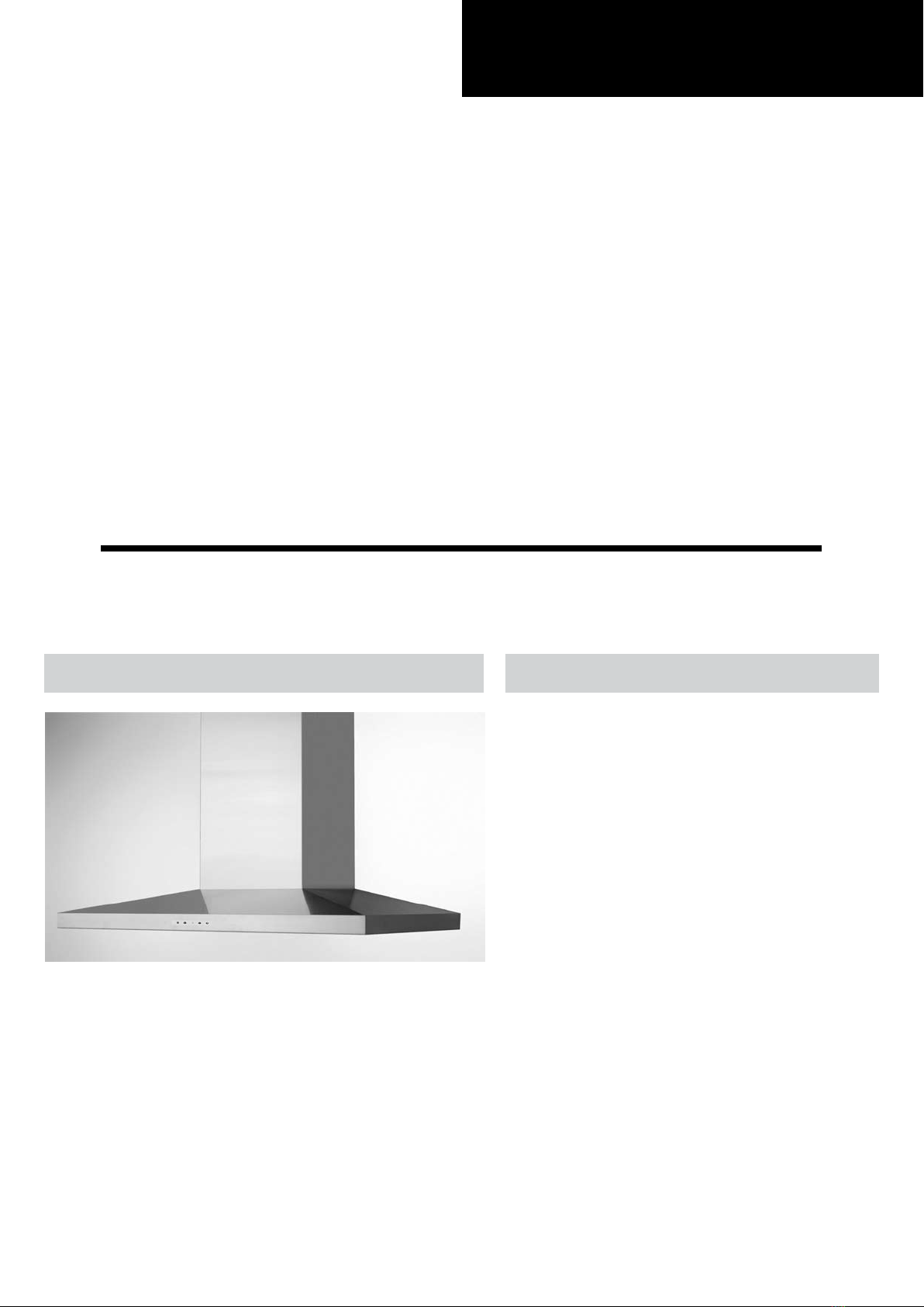
Tiger
SERVICE Manual
RANGE HOOD CONTENTS
• Safety precautions
• Distance from the hob
• Technical specications
• Technical data
• Parts supplied
• Non-return valve - parts supplied
• Aluminium panel / charcoal lter
• Installation
• Control drawing
• Touch control
• Bulbs
• Transformer
• Power board
• Electrical assembly
• Wiring diagram
• Motor
• Condenser
• Exploded view
• Spare parts list
• Troubleshooting


SUMMARY
Safety precautions........................................................................................................................41.
Distance from the hob.................................................................................................................72.
Technical specifications................................................................................................................83.
Technical data...............................................................................................................................94.
Parts supplied ............................................................................................................................105.
Non-return valve - parts supplied ............................................................................................116.
Aluminium panel / charcoal filter ............................................................................................127.
7.1 replacing the aluminum panel
7.2 replacing the charcoal filter
Installation..............................................................................................................138.
8.1 fixing the appliance to a wall
8.2 fixing the decorative telescopic flue
8.3 installing the charcoal filters and aluminum panels
Control drawing............................................................................................................................199.
9.1 configuration
9.2 technical drawing of control board
10. Touch control...............................................................................................................................21
10.1 replacing the touch control
11. Bulbs............................................................................................................................................24
11.1 replacing the halogen bulbs
11.2 replacing the halogen bulbs socket
12. Transformer..................................................................................................................................26
12.1 replacing the transformer
13. Power board.................................................................................................................................30
13.1 replacing the power board
14. Electrical assembly......................................................................................................................32
15. Wiring diagram............................................................................................................................33
16. Motor............................................................................................................................................34
16.1 replacing the motor
17. Condenser...................................................................................................................................39
17.1 replacing the condenser
18. Exploded view..............................................................................................................................41
19. Spare parts list............................................................................................................................42
20. Troubleshooting...........................................................................................................................43
- 3 -

Before connecting the model to the electricity
network:
- Check the data plate (positioned inside the ap-
pliance) to ascertain that the voltage and power
correspond to the supply circuit. If in doubt ask a
qualied electrician.
- If the power supply cable is damaged, it must be
replaced with another cable or a special assembly,
which may be obtained direct from the manufac-
turer.
- This device must be connected to the supply
circuit through a hardwired spur protected by 3A
fuse.
WARNING !
In certain circumstances electrical appliances
may be a danger hazard.
A) Do not check the status of the filters while
the cooker hood is operating
B) Do not touch bulbs or adjacent areas, du-
ring or straight after prolonged use of the ligh-
ting installation
C) Flambè (Flamed) cooking is prohibited un-
derneath the cooker hood
D) Avoid free flame, as it is damaging for the
filters and a fire hazard
E) Constantly check food frying to avoid that
the overheated oil may become a fire hazard
F) Disconnect the electrical plug prior to any
maintenance
G) This appliance is not intended for use by
young children or infirm persons without su-
pervision
H) Young children should be supervised to en-
sure they do not play with the appliance
I) There shall be adequate ventilation of the
room when the rangehood is used at the same
time as appliances burning gas or other fuels
L) There is a risk of fire if cleaning is not carri-
ed out in accordance with the instructions
M) Please use a dedicated plug receptacle for
power plug
N) Please don’t operate the hood when there is
a flame on the dishes or frying pan
O) Please don’t touch the product or operate
the switch with wet hands
P) Please don’t wipe off the hood with the che-
micals when cleaning.
The symbol on the product or on the accom-
panying paperwork indicates that the applian-
ce should not be treated as domestic waste, but
should be delivered to a suitable electric and elec-
tronic appliance recycling collection point. Follow
local guidelines when disposing of waste. For
more information on the treatment, re-use and re-
cycling of this product, please contact your local
authority, domestic waste collection service or the
shop where the appliance was purchased.
Assembly and electrical connections must be
carried out by specialised personnel.
• Electric Connection
The connection to the mains is carried out as fol-
lows:
BLACK = L line
WHITE = N neutral
GREEN/YELLOW = G ground
Connect to a junction box suitable for the electrical
load indicated on the description label.
An omnipolar switch with a minimum opening of
3mm between contacts, in line with the electrical
load and local standards, must be placed between
the appliance and the network in the case of direct
connection to the electrical network.
Before proceeding with the assembly operations,
remove the anti-grease filter(s) so that the unit is
easier to handle.
In the case of assembly of the appliance in the
venting version prepare the hole for evacuation of
the air.
• We recommend the use of an air exhaust tube
which has the same diameter as the air exhaust
outlet hole. If a pipe with a smaller diameter is
used, the efficiency of the product may be redu-
ced and its operation may become noisier.
Safety precautions
- 4 -

Safety precautions
- 5 -
• We recommend that the cooker hood is switched
on before any food is cooked. We also recommend
that the appliance is left running for 15 minutes
after the food is cooked, in order to thoroughly eli-
minate all contaminated air.
The effective performance of the cooker hood de-
pends on constant maintenance; the anti-grease
filter and the active carbon filter both require spe-
cial attention.
• The anti-grease filter is used to trap any grease
particles suspended in the air, therefore is subject
to saturation (the time it takes for the filter to be-
come saturated depends on the way in which the
appliance is used).
- To prevent potential re hazards, the anti-grease
lters should be washed a minimum of every 2
months (it is possible to use the dishwasher for
this task).
- After a few washes, the colour of the lters may
change. This does not mean they have to be
replaced.
If the replacement and washing instructions are
not followed, the anti-grease lters may present a
re hazard.
• The acrylic filter, which is found resting on the
grille, should be replaced when the text, visible
through the grille, changes colour and the ink
spreads; the new filter should be fitted in such a
way that the text can be seen through the grille
from outside the cooker hood.
• If the filters do not have any text on them, or if
metal filters or aluminium panel filters are used,
they should be washed every 2 months in order to
prevent the risk of fire.
To wash the filters, proceed as follows:
- Remove the filter from the grille and wash it using
a solution of water and neutral liquid detergent, le-
aving the dirt to soften.
- Rinse thoroughly with warm water and leave to
dry.
• The active carbon filters are used to purify the
air which is released back into the room. The fil-
ters are not washable or re-usable and must be
replaced at least once every four months. The ac-
tive carbon filter saturation level depends on the
frequency with which the appliance is used, the
type of cooking performed and the regularity with
which the anti-grease filters are cleaned.
• Remove build-up from the fan and other surfaces
of the cooker hood regularly using a cloth moistened
with denatured alcohol or non-abrasive neutral liquid
detergent.
CAUTION!
Wear gloves during the installation of the product
otherwise injury at ngers could happen by sharp ed-
ges.
Safety precautions
WARNING !
• Take care when the cooker hood is operating simultaneously with an open fireplace or burner that
depend on the air in the environment and are supplied by other than electrical energy, as the cooker
hood removes the air from the environment which a burner or fireplace need for combustion. The ne-
gative pressure in the environment must not exceed 4Pa (0.016 WC.). Provide adequate ventilation in
the environment for a safe operation of the cooker hood. Follow the local laws applicable for external
air evacuation.
- 6 -

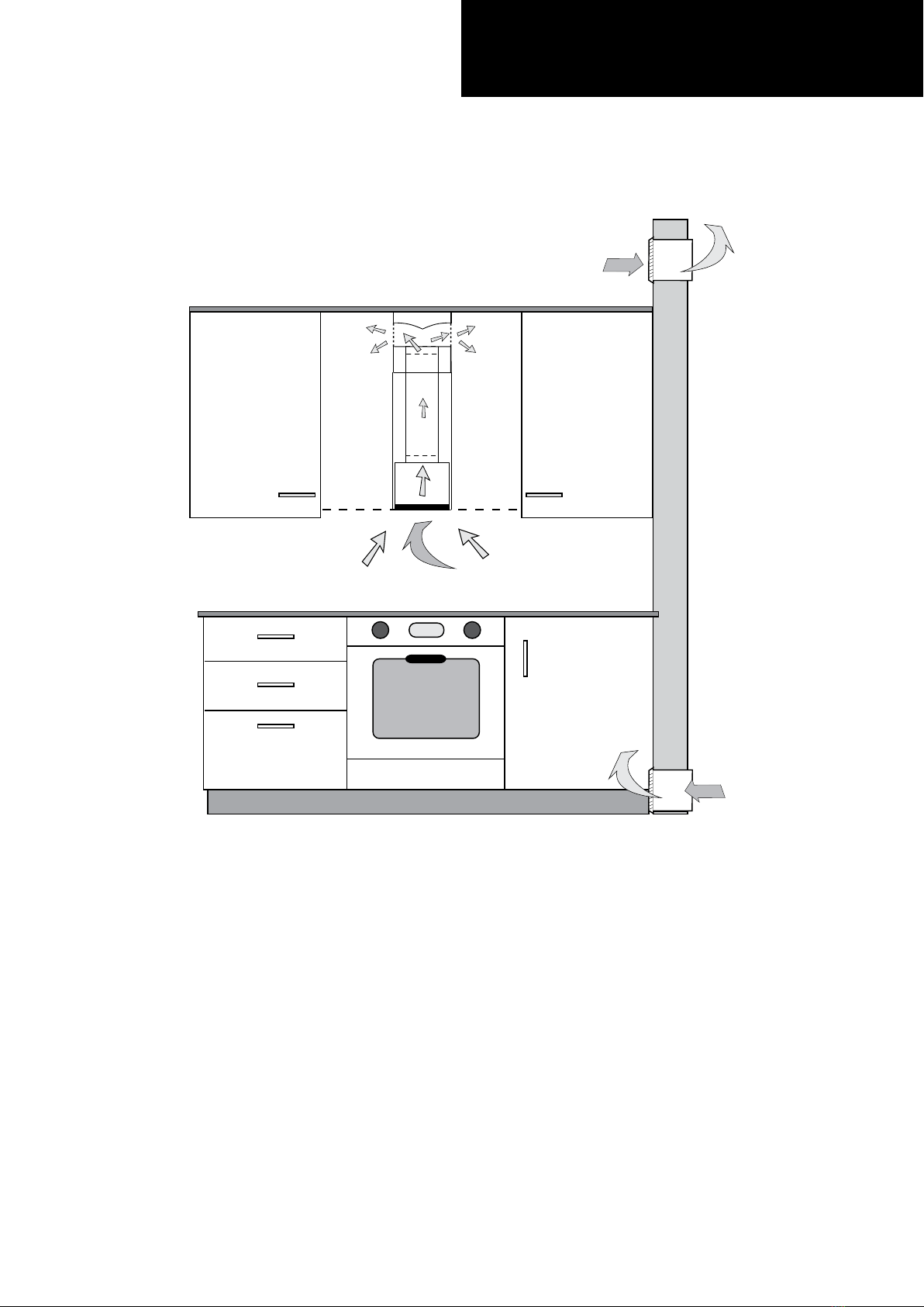
Distance from the hob
• The minimum distance between the support surfaces of the cooking pots on the cooker top and the lowest
part of the cooker hood must be at least 650 mm.
If a venting tube composed of two parts is used, the upper part must be placed outside the lower part.
Do not connect the cooker hood exhaust to the same conductor used to circulate hot air or for evacuating
fumes from other appliances generated by other than an electrical source.
- 7 -

Technical specifications
CONTROLS
ALUMINIUM PANELS LIGHT
MODEL Tiger
Size 30’’
Finish St.steel
Motor HB4
Extracting power (CFM) 600
Voltage 110-120V ~ 60Hz
Motor power consumption 1 x 420 W
Product certication UL
Product class Class I
Type model PVWT930S1SV
Air outlet diameter (mm) 150
Controls Touch Control
Speeds 3+1
Version Duct out
Filters Aluminium panels
Charcoal Filters 2 Circular lters
Bulbs 2 x 20 W Halogen lamps
Weight Gross 20,3 Kg
- 8 -
DUCTS
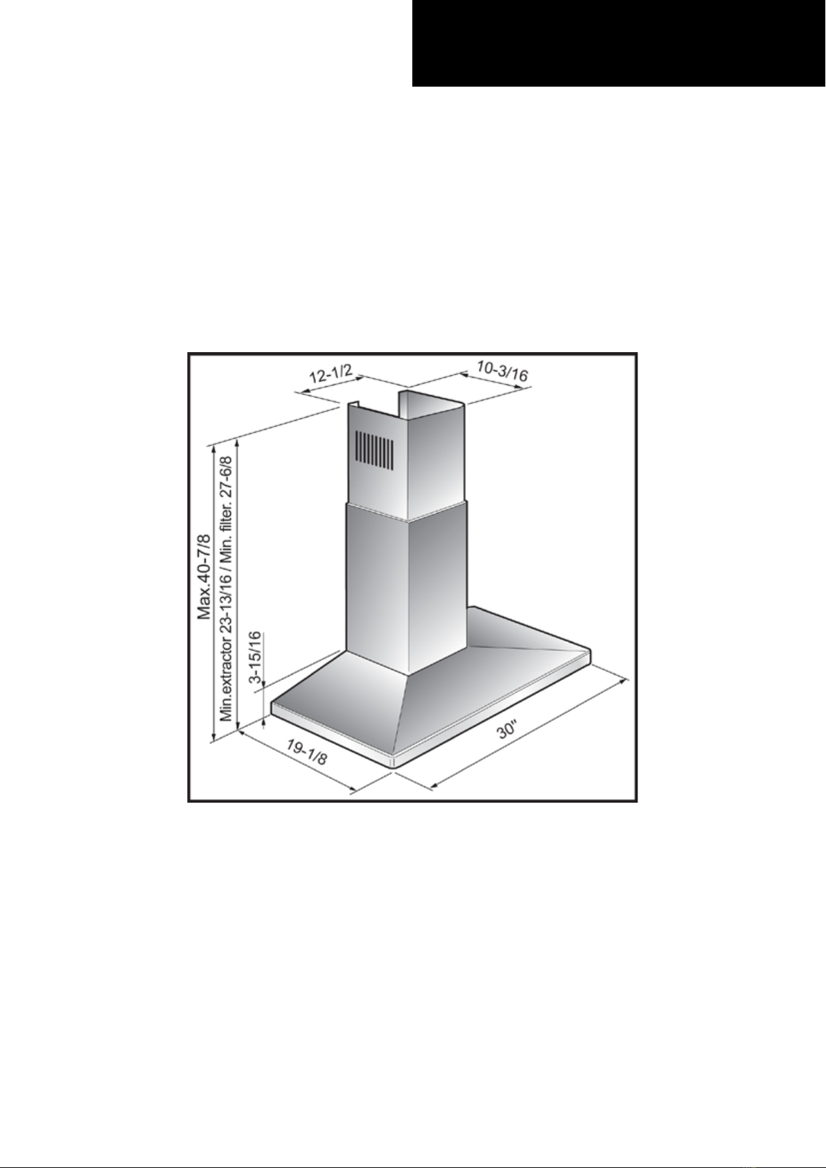
Technical data
- 9 -
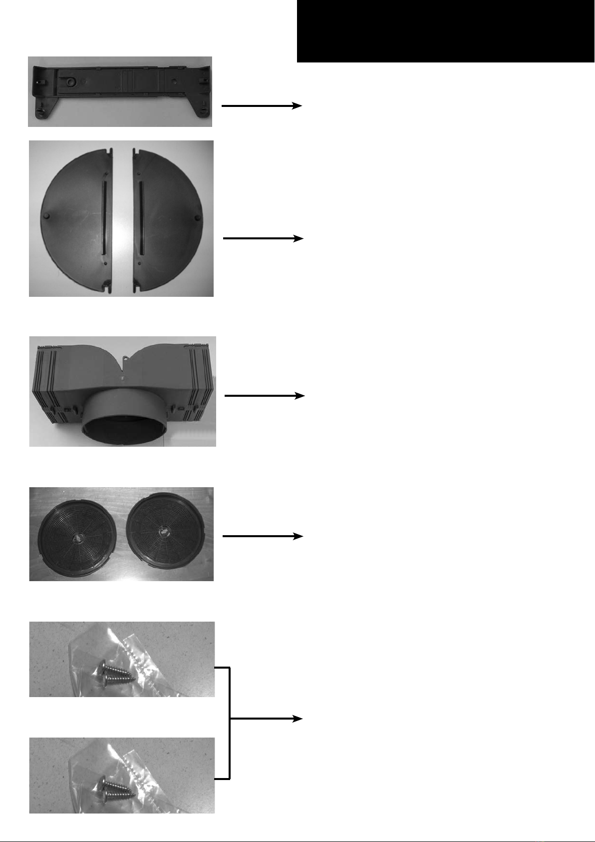
Parts supplied
- 10 -
NON RETURN VALVE
CHIMNEY BRACKET
AIR DEVIATOR
(air recirculation option only)
2 CHARCOAL FILTERS
(air recirculation option only)
MOUNTING SCREWS

Non-return valve
parts supplied
- 11 -
The non-return valve (exhaust damper) is recom-
mended when the appliance is installed in the ex-
tracting version, to prevent cold air blowing back in
from outside.
The valve is made up of two parts which must be
fixed to the air outlet flange on the motor assembly
If the appliance is installed in the recirculation filte-
ring version, the non-return valve is not necessary.
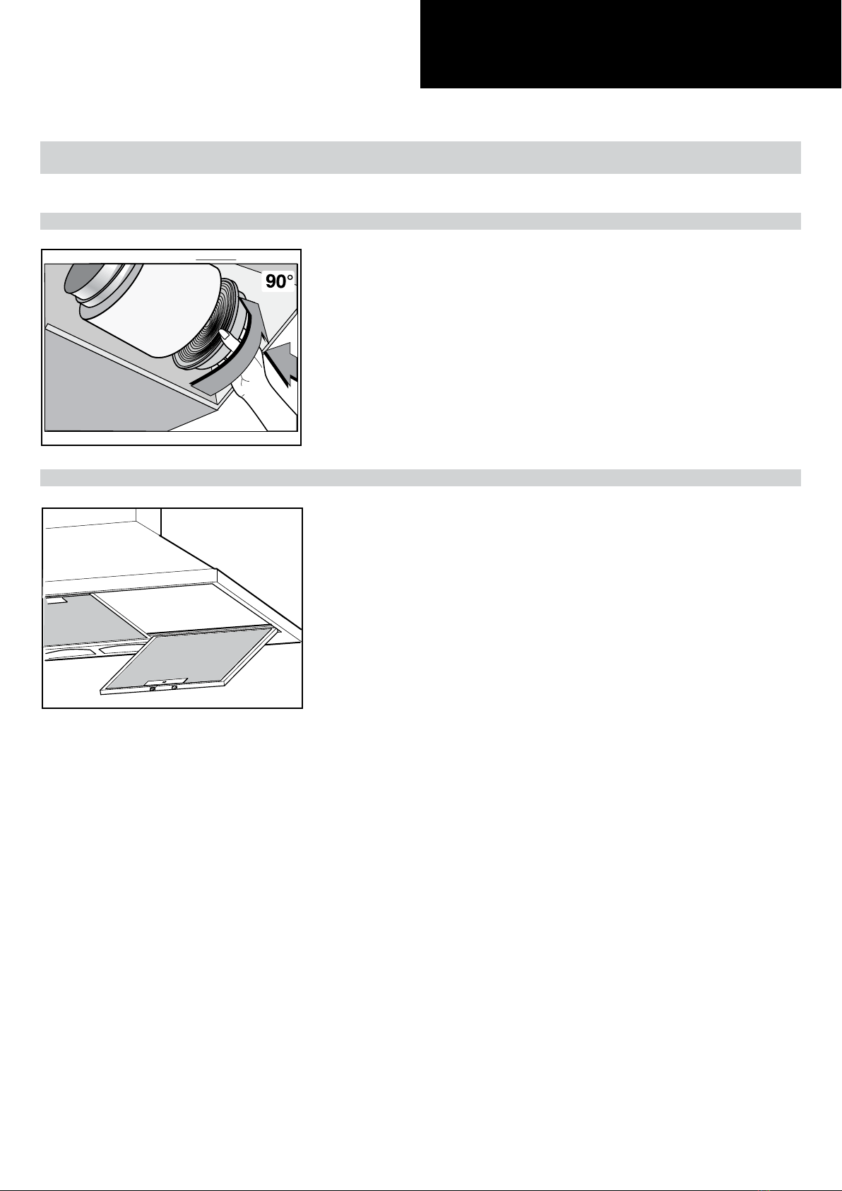
- 12 -
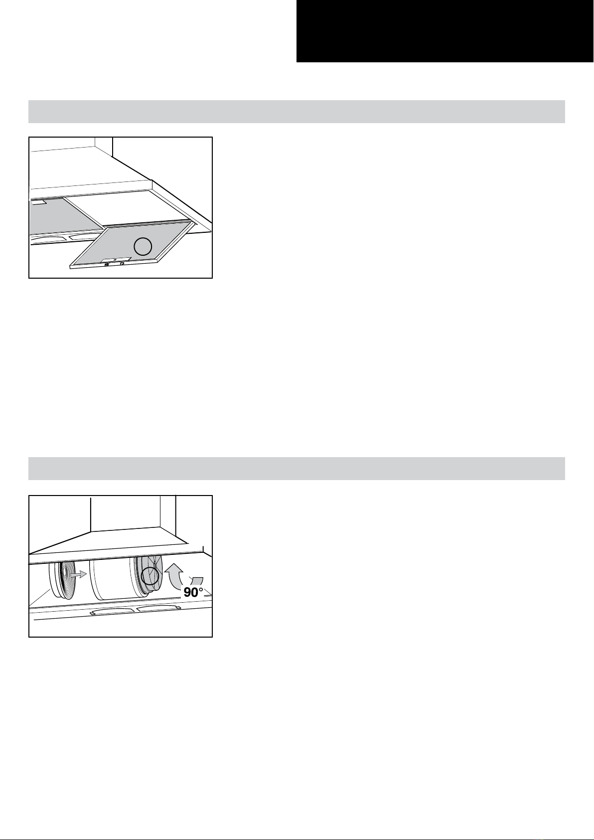
Aluminium panel
Charcoal filter
The metal filters and/or aluminium panel are also dishwasher
safe. If the filters are made using aluminium, or if an alumi-
nium panel is used, after a few washes the colour may chan-
ge. This does not mean they have to be replaced.
If the replacement and washing instructions are not followed,
the anti-grease filters may present a fire hazard.
To replace the aluminium panels, simply operate the handle
(a) provided for the purpose, as illustrated in the drawing.
The active carbon filters are used to purify the air which is
released back into the room. The filters are not washable or
re-usable and must be replaced at least once every four mon-
ths. The active carbon filter saturation level depends on the
frequency with which the appliance is used, the type of coo-
king performed and the regularity with which the anti-grease
filters are cleaned.
To replace the active charcoal filters, simply operate the han-
dle provided for the purpose, as illustrated in the drawing.
Replacing the aluminium panel (a) 7.1
Replacing the charcoal lter (b) 7.2
a
b
- 13 -
Installation
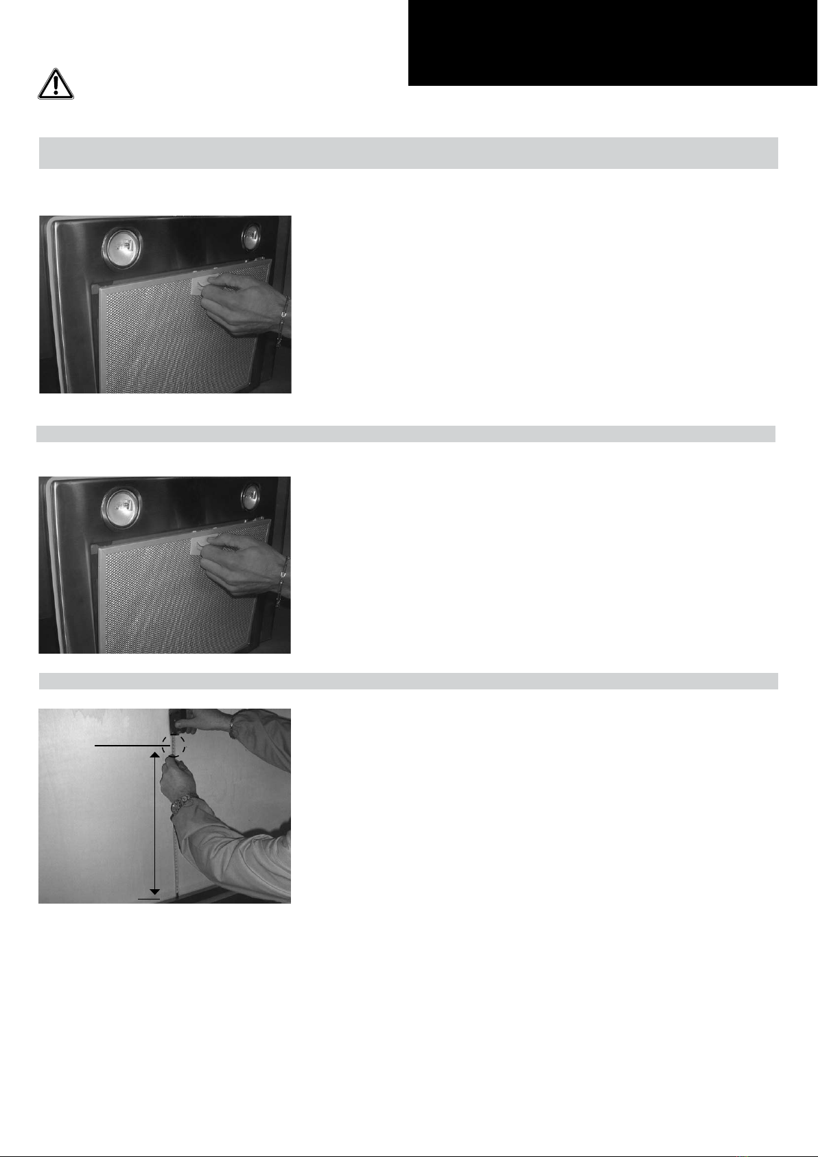
Fixing the appliance to a wall 8.1
Phase 1
Phase 2
Before starting to fix the hood, disconnect the anti-grease
filter for easier appliance handing. Before this operation, per-
form the following steps:
Phase 1
- Pull handle as shown in the picture and remove the anti-
grease filter.
Phase 2
- Check the distance between the surface of the cooking de-
vice and the bottom surface of the cooker hood, which must
be not less than 650 mm. Mark the position of the lower side
of the hood on the wall.
650 mm
CAUTION!
Wear gloves during the installation of the product otherwise injury at ngers could happen by sharp edges.

- 14 -
Installation
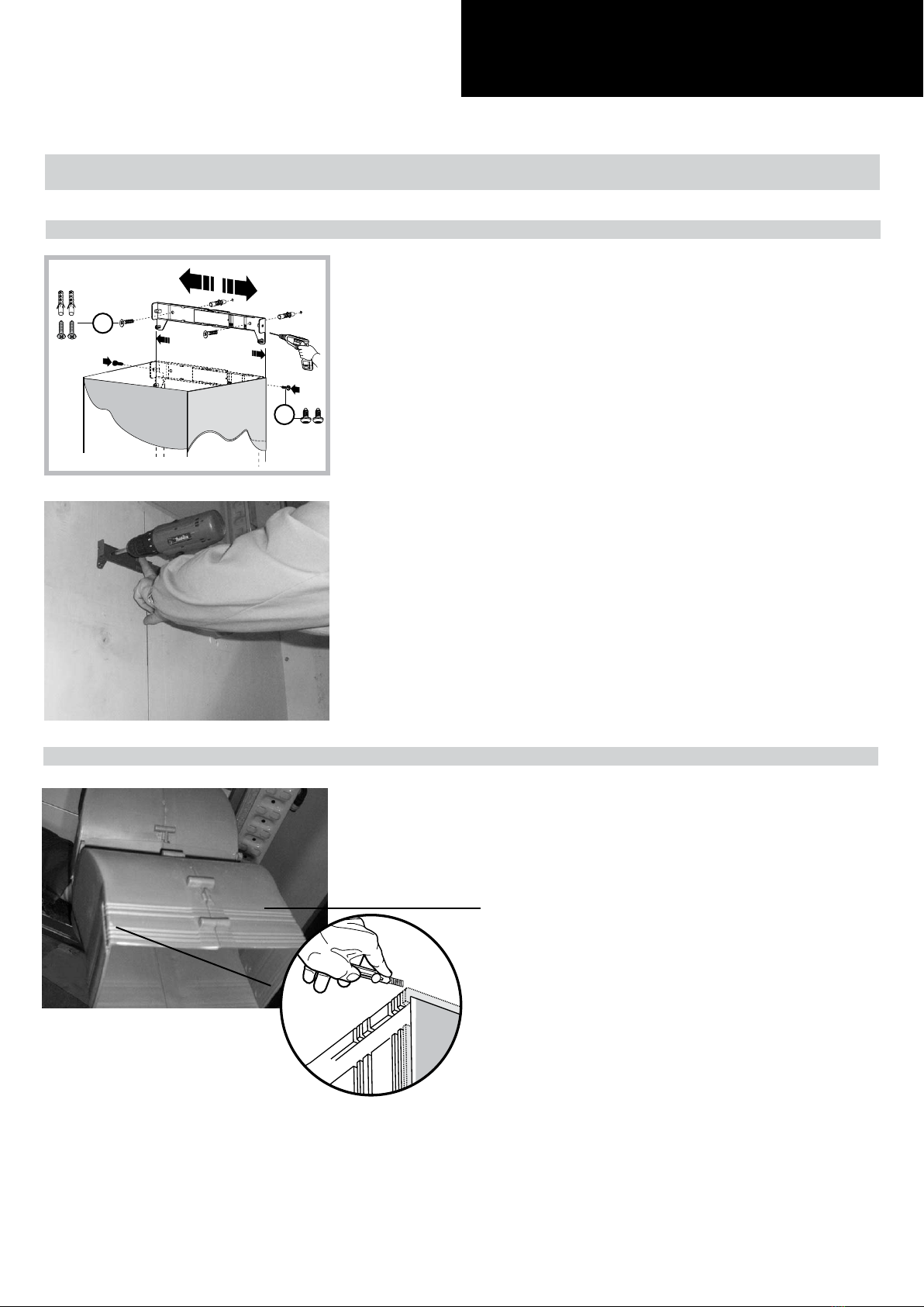
Phase 3
Phase 4
Phase 3
- Drill the holes Arespecting the distances indicated. Fix the ap-
pliance to the wall and align it in horizontal position to the wall
units.
Phase 4
- When the appliance has been adjusted, tightly secure the
hood using the screws A. For the various installations use
screws and screw anchors suited to the type of wall (e.g. rein-
forced concrete, plasterboard, etc.). If the screws and screw
anchors are provided with the product, check that they are
suitable for the type of wall on which the hood is to be fixed.
The hood is now fixed to the wall.
�
- 15 -
Fixing the decorative telescopic ue 8.2
Installation
Phase 2
Phase 1
- Arrange the electrical power supply within the dimensions of
the decorative ue. If your appliance is to be installed in the
ducting version or in the version with external motor, prepare
the air exhaust opening.
- Adjust the width of the support bracket of the upper ue.
- Then x it to the ceiling using the screws A in such a way
that it is in line with your hood and respecting the distance
from the ceiling.
Phase 2 (air recirculation option only)
- Cut the air deviator D with a cutter, following carefully the
first pre-cut starting from the outer edge on both sides, as
indicated in the picture.
Air deviator D
Phase 1
A
B

- 16 -
Installation
D
C
C
D
Phase 3 (air recirculation option only)
- Take the air deviator D and make two holes as shown in the
photographs.
- Secure the duct fixing bracket to the air deviator D as shown
in the photograph.
Phase 4
- Carry out final fixing of the air deflector D to the wall with a
fixing screw as shown in the photograph.
Phase 4
D
Phase 3
Ø 6
- 17 -
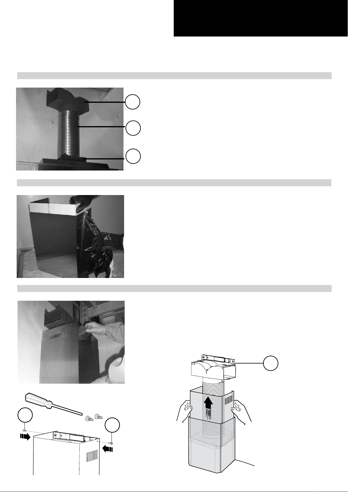
Phase 7
Phase 7
- Extend the upper decorative duct as far as bracket C and fix
it in place using screws X.
Installation
��
C
Phase 5
D
F
G
Phase 6
Phase 5 (air recirculation option only)
- Connect the flexible pipe (not supplied) to the deviator D.
- Fix the flexible pipe onto the connector flange G.
Phase 6
- Take care not to scratch the duct; wear gloves when remov-
ing the protective lm.
- 18 -
Installation
Installing the charcoal lters and aluminum panels 8.3
Phase 1
Phase 2
Phase 1
- Take the active charcoal filters and position them in their
housings.
Phase 2
- Take the aluminum panels and position them in their hou-
sings.

- 19 -
Control drawing
Conguration 9.1
Push-button A = On/off lights switch.
Push-button B = On/off cooker hood switch. The appliance switches on at speed level 1, If the cooker
hood is on depress the push-button for 2 sec. to switch off the cooker hood. If the cooker hood is at
speed level 1 it will not be necessary to depress the push-button to switch the cooker hood off. De-
creases the motor speed.
Display C = Indicates the motor speed level selected and activates the timer.
Push-button D = Switches on the cooker hood. Increases the motor speed. Touching the key at 3rd
speed, the intensive function runs for 10 minutes, then the appliance go back to work at the original
speed. During this function the display blinks.
Key E = The Timer times the functions on activation for 15 minutes, after which they are switched off.
The Timer is deactivated by re-pressing Key E. When the Timer is activated the decimal point must
flash on the display. The Timer cannot be activated if the intensive speed is functioning.
- The “clean air” function is activated by pressing key E for 2 seconds when the appliance is
switched off. This switches the motor on for 10 minutes every hour at the first speed. During functioning
a rotary movement of the peripheral segments must be visualised on the display.
When this time has passed the motor switches off and the fixed letter “C” must be visualised on the
display until the motor re-starts after 50 minutes for another 10 minutes and so on. Press any key apart
from the light keys to return to normal functioning. Press key E to deactivate the function.
• Active carbon/grease filter saturation:
- When display item C flashes, at a speed where it alternates with the letter F (e.g. 1 and F), the
grease filters must be washed.
- When display item C flashes, at a speed where it alternates with the letter A (e.g. 1 and A), the
carbon filters must be replaced.
After the clean filter has been positioned correctly, the electronic memory must be reset by pressing
button A for approximately 5 seconds, until the indication F or A shown on the display C stops flash-
ing.

- 20 -
Control drawing
Technical drawing of control board 9.2
Table of contents
Other Tecnowind Ventilation Hood manuals


Popular Ventilation Hood manuals by other brands


KRONAsteel
KRONAsteel ANGELICA 600 white sensor manual

KitchenAid
KitchenAid KWCU360JSS1 Installation instructions and use and care guide

Franke
Franke FBI 502 Instructions for use and installation

Rinnai
Rinnai RH-S3056-PBW Operation & installation manual

CDA
CDA EVP6 Installation and maintenance manual

ROSIERES
ROSIERES RBVSI985IN Installation and user manual