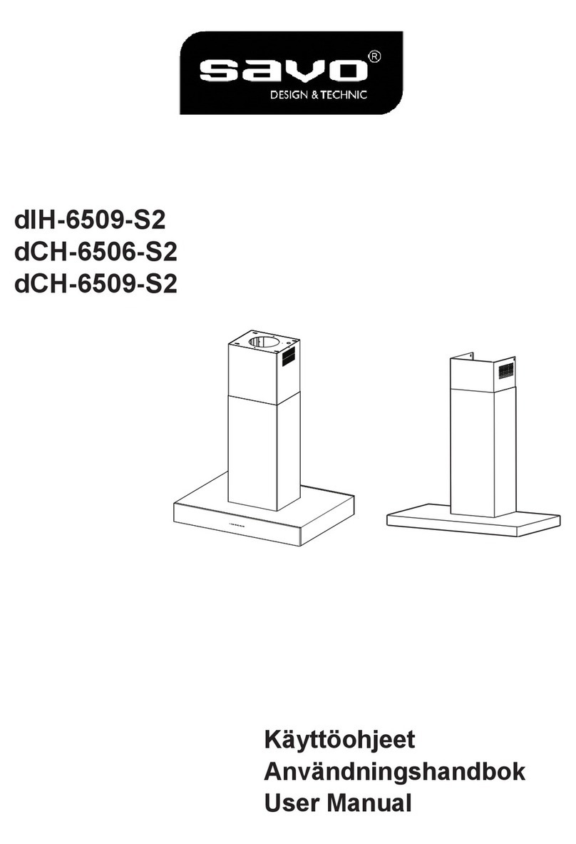
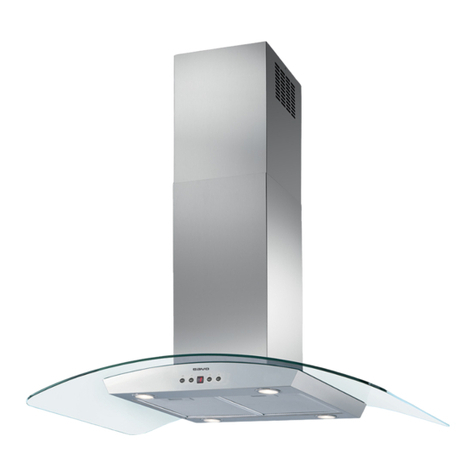
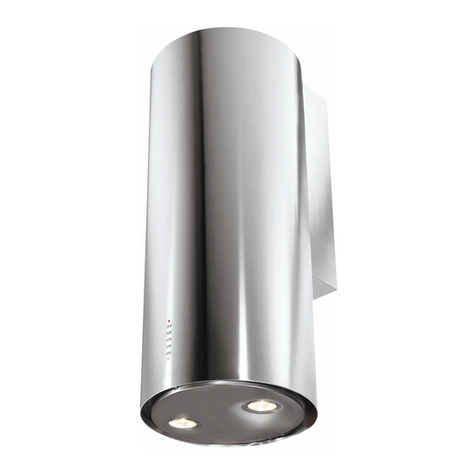
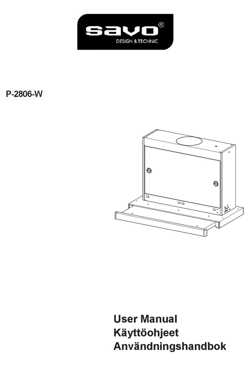
Savo NOPPA User manual

NOPPA
Instructions Manual
Käyttöohje

2
2
INDEX
SAFETYINFORMATION......................................................................................................................................................... 3
CHARACTERISTICS.............................................................................................................................................................6
INSTALLATION...................................................................................................................................................................... 8
USE...................................................................................................................................................................................... 11
CAREANDCLEANING.........................................................................................................................................................12
SISÄLTÖ
TURVALLISUUSTIETOJA.....................................................................................................................................................13
MITAT JA OSAT .................................................................................................................................................................. 16
ASENNUS............................................................................................................................................................................ 18
KÄYTTÖ............................................................................................................................................................................... 21
PUHDISTUSJAHUOLTO..................................................................................................................................................... 22
EN
FI

EN 3
3
SAFETY INFORMATION
For your safety and correct operation of the appliance, read this manual
carefully before installation and use. Always keep these instructions
with the appliance even if you move or sell it. Users must fully know the
operation and safety features of the appliance.
The wire connection has to be done by specialized technician.
The manufacturer will not be held liable for any damages resulting from
incorrect or improper installation.
The minimum safety distance between the cooker top and the extractor
hood is 650 mm (some models can be installed at a lower height,
please refer to the paragraphs on working dimensions and installation).
If the instructions for installation of the gas hob specify a greater
distance, this must be respected.
Check that the mains voltage corresponds to that indicated on the
rating plate fixed to the inside of the hood.
Means for disconnection must be incorporated in the fixed wiring in
accordance with the wiring rules.
For Class I appliances, check that the domestic power supply
guarantees adequate earthing.
Connect the extractor to the exhaust flue through a pipe of minimum
diameter 120 mm. The route of the flue must be as short as possible.
Regulations concerning the discharge of air have to be fulfilled.
Do not connect the extractor hood to exhaust ducts carrying
combustion fumes (boilers, fireplaces, etc.).

EN 4
4
If the extractor is used in conjunction with non-electrical appliances
(e.g. gas burning appliances), a sufficient degree of aeration must be
guaranteed in the room in order to prevent the backflow of exhaust gas.
When the cooker hood is used in conjunction with appliances supplied
with energy other than electric, the negative pressurein the room must
not exceed 0,04 mbar to prevent fumes being drawn back into the room
by the cooker hood.
The air must not be discharged into a flue that is used for exhausting
fumes from appliances burning gas or other fuels.
If the supply cord is damaged, it must be replaced from the manufac-
turer or its service agent.
Connect the plug to a socket complying with current regulations, lo-
cated in an accessible place.
With regards to the technical and safety measures to be adopted for
fume discharging it is important to closely follow the regulations pro-
vided by the local authorities.
WARNING: Before installing the Hood, remove the protective films.
Use only screws and small parts supplied with the hood.
WARNING: Failure to install the screws or fixing device in accordance
with these instructions may result in electrical hazards.
Do not look directly at the light through optical devices (binoculars,
magnifying glasses…).
Do not flambè under the range hood; risk of fire.
This appliance can be used by children aged from 8 years and above
and persons with reduced physical, sensory or mental capabilities or
lack of experience and knowledge if they have been given supervision
or instruction concerning use of the appliance in a safe way and under-
stand the hazards involved. Children shall not play with the appliance.
Cleaning and user maintenance shall not be made by children without
supervision.
Children should be supervised to ensure that they do not play with the
appliance.

EN 5
5
The appliance is not to be used by persons (including children) with re-
duced physical, sensory or mental capabilities, or lack of experience
and knowledge, unless they have been given supervision or instruction.
Accessible parts may become hot when used with cooking appliances.
Clean and/or replace the Filters after the specified time period (Fire
hazard). See paragraph Care and Cleaning.
There shall be adequate ventilation of the room when the range hood is
used at the same time as appliances burning gas or other fuels (not
applicable to appliances that only discharge the air back into the room).
The symbol on the product or on its packaging indicates that this
product may not be treated as household waste. Instead it shall be
handed over to the applicable collection point for the recycling of elec-
trical and electronic equipment. By ensuring this product is disposed of
correctly, you will help prevent potential negative consequences for the
environment and human health, which could otherwise be caused by
inappropriate waste handling of this product. For more detailed informa-
tion about recycling of this product, please contact your local city office,
your household waste disposal service or the shop where you pur-
chased the product.

EN 6
6
CHARACTERISTICS
Components
Ref. Q.ty Product Components
1 1 Hood Canopy, complete with: Controls,
Light, Fan unit, Filters
21 Telescopic chimney, comprising:
2.1 1 Upper chimney
2.2 1 Lower chimney
9 1 Reduction flange ø 150-120 mm
10 1 Damper ø 150
15 1 Air Outlet Connector
19 1 Chimney Fixing Element
Ref. Q.ty Components for Installation
7.2.1 2 Upper Chimney Fixing Brackets
11 5 Plugs
11a 2 Plugs SB 12/10
12a 5 Screws 4.2 x 44.4
12c 10 Screws 2.9 x 6.5
Q.ty Documentation
1 Instruction Manual

EN 7
7
Dimensions
450
380 430
126
81 41.5
300
260
62.5
340
* * MIN 460 - MAX 660
* MIN 340 - MAX 660
400
* * MIN 875 - MAX 1075
* MIN 755 - MAX 1075
6
* Dimensions of the hood in ducting version.
** Dimensions of the hood in recycling version.

EN 8
8
INSTALLATION
Drilling the Wall
373
105
150 150
12a
Mark the following on the wall:
• a vertical line up to the ceiling or surface above the hood, at the centre of the area in which
the hood itself is to be fitted;
• a horizontal line at: 650 mm min. above the Hob;
• Rest the Bracket 7.2.1 as indicated, 1-2 mm from the ceiling or surface above the hood,
aligning its centre (grooves) with the vertical reference line.
• Mark the centres of the holes in the bracket.
• Rest the Bracket 7.2.1 as indicated, X mm under the first bracket (X = height of the Upper
chimney provided), aligning its centre (grooves) with the vertical reference line.
• Mark the centres of the holes in the bracket.
• Mark a reference point as indicated at 105 mm from the horizontal reference line.
• Drill the points marked using an ø 8 mm bit.
• Insert the plugs 11 into the holes.
• Fix the Brackets, using the screws 12a (4.2 x 44.4) provided.
• As indicated above, mark a reference point 373 mm above the horizontal reference line, and
150 mm to the right of the vertical reference line.
• Repeat this operation on the opposite side, checking to ensure it is level.
• Drill the points marked using an ø 12 mm bit.
• Insert the plugs, screws and bracket 11a into the holes, and fasten.

EN 9
9
Mounting the hood body
• Remove the metal grease filters by turning the handles
provided.
•Adjust the two screws Vr, on brackets 11a, to a mini-
mum.
• Hook the hood canopy onto the two brackets 11a.
• From inside the hood canopy, adjust the screws Vr to
set the Hood Canopy level.
• Tighten the safety screws 12a.
Connections
DUCTED VERSION AIR EXHAUST SYSTEM
When installing the ducted version, connect the hood to
the chimney using either a flexible or rigid pipe ø 150 or
120mm, the choice of which is left to the installer.
To install a ø 150 pipe
• To install the dumper 10
• Fix the pipe in position using sufficient pipe clamps
(not supplied).
To install a ø 120 pipe
• To install a ø 120 mm air exhaust connection, insert the
reducer flange 9on the dumper 10.
• Fix the pipe in position using sufficient pipe clamps
(not supplied).
• Remove any activated charcoal filters.
AIR OUTLET – RECIRCULATION VERSION
•Unfasten the 2 screws fixing the upper bracket 7.2.1.
• Fasten the air outlet connector 15 in its place, using the
2 screws removed as above.
• Join the Connector 15 to the Hood canopy outlet using a
rigid or flexible pipe ø150 mm, selection of which is at
the discretion of the installation technician.
• Make sure that the Activated charcoal odour filter has
been fitted.

EN 1
10
ELECTRICAL CONNECTION
• Connect the hood to the mains through a two-pole switch
having a contact gap of at least 3 mm.
• Remove the grease filters (see paragraph Maintenance)
being sure that the connector of the feeding cable is cor-
rectly inserted in the socket placed on the side of the fan.
Chimney Assembly
• Fasten the Chimney fixing element 19 to the Body using
4 screws 12c.
Upper chimney
• Open the two side pieces out slightly, hook them up be-
hind the brackets 7.2.1 and bring them back together
again until they are in contact.
• Fix to the Brackets at the sides, using 4 screws 12c (2.9 x
9.5) provided.
• If there are any, make sure that the Connector extensions
outlet is in correspondence with the Chimney openings.
Lower chimney
• Open the two side pieces of the Chimney out slightly,
hook them between the upper chimney and the wall, and
then close them together again until they are in contact.
• Fix the part at the sides to the Chimney fixing element
19, using 2 screws 12c (2.9 x 9.5) provided.

EN 1
11
USE
T2
T1 L
T3
Control panel
BUTTON LED FUNCTIONS
T1 Speed On Turns the Motor on at Speed one.
Turns the Motor off.
T2 Speed On Turns the Motor on at Speed two.
T3 Speed Fixed When pressed briefly, turns the Motor on at Speed three.
Flashing Pressed for 2 Seconds.
Activates Speed four with a timer set to 6 minutes, after which
it returns to the speed that was set previously. Suitable to deal
with maximum levels of cooking fumes.
LLight Turns the Lighting System on and off.
Warning: Button T1 turns the motor off, after first passing to speed one.

EN 1
12
CARE AND CLEANING
Grease filters
CLEANING METAL SELF- SUPPORTING GREASE FILTERS
• The filters must be cleaned every 2 months of operation, or
more frequently for particularly heavy usage, and can be
washed in a dishwasher.
• Remove the filters one at a time by pushing them towards the
back of the group and pulling down at the same time.
• Wash the filters, taking care not to bend them. Allow them to
dry before refitting.
• When refitting the filters, make sure that the handle is visible
on the outside.
Activated charcoal filter (Recirculation version)
These filters are not washable and cannot be regenerated, and
must be replaced approximately every 4 months of operation, or
more frequently with heavy usage.
REPLACING THE ACTIVATED CHARCOAL FILTER
• Remove the metal grease filters
• Remove the saturated activated charcoal filter as shown (A).
• Fit the new filters (B).
• Replace the metal grease filters.
A
B
Lighting unit
• For replacement contact technical support ("To purchase
contact technical support").

FI 1
13
TURVALLISUUSTIETOJA
Lue tämäkäyttöopashuolellisesti ennen laitteen asentamistaja käyttöä
omanturvallisuutesija laitteen oikeantoiminnan takaamiseksi. Pidä nämä
ohjeet aina laitteen lähettyvillä, niiden täytyyseuratalaitetta myös, josse
myydääntailuovutetaan kolmansilleosapuolille.On tärkeää, että käyttäjät
tuntevatlaitteentoiminta- ja turvallisuusominaisuudet.
Johtojenliitännän saa tehdä vain päteväteknikko.
Valmistajaei vastaa väärästäasennuksestatai käytöstä aiheutuneista
vahingoista.
Pienin turvallinen etäisyys keittotason ja liesituulettimen välilläon 650 mm
(jotkutmallitvoidaan asentaa alemmas, katsotyö-ja asennusmittoja
koskevaakappaletta).
Joskaasukäyttöisenkeittotason asennusohjeet määräävät,että
etäisyyden on oltava yllämainittua suurempi, ohjeita on noudatettava.
Tarkista,ettäsähköverkon jännitevastaaliesituulettimen sisällä olevan
arvokilventietoja.
Erotuskytkimetonasennettava kiinteään järjestelmään
kaapelointijärjestelmiäkoskevienmääräysten mukaisesti.
LuokanIlaitteita varten on tarkistettava,ettäkodin sähköverkossa on
sopivamaadoitus.
Liitäliesituuletinsavuhormiin putkella, jonka läpimittaon vähintään 120
mm.Savunpoistoreitin on oltavamahdollisimmanlyhyt.
Kaikkiailmanpoistoa koskevia määräyksiä onnoudatettava.
Äläliitäliesituuletinta savukanaviin,joidenkautta poistetaan
palamishöyryjä (esimerkiksi lämmityskattilat,takatjne.).

FI 1
14
Jos liesituuletinta käytetään yhdessä muiden kuin sähkölaitteiden
(esimerkiksi kaasulaitteiden) kanssa, on pystyttävä takaamaan riittävä
huoneen tuuletus poistokaasujen paluuvirtauksen estämiseksi. Kun
liesituuletinta käytetään yhdessä muiden kuin sähkölaitteiden kanssa,
huoneen negatiivinen paine ei saa ylittää 0,04 mbar, jotta liesituuletin ei
palautahöyryjähuoneeseen.
Ilmaa ei saa poistaa sellaisen putken kautta, jota käytetään kaasulla tai
muillapolttoaineillatoimivien laitteiden savun imemiseen.
Jos virtajohto vahingoittuu, sen saa vaihtaa vain valmistaja tai
huoltopalvelunteknikko.
Kytke pistoke voimassa olevien määräysten mukaiseen ja saavutettavissa
olevaanpistorasiaan.
Savunpoistoa koskevien teknisten ja turvallisuuteen liittyvien toimenpiteiden
suhteen on noudatettava tarkkaan paikallisten viranomaisten antamia
määräyksiä.
VAROITUS: Poistasuojakalvotennen liesituulettimen asentamista.
Käytävainliesituulettimelle sopivia ruuveja ja kiinnitysosia.
VAROITUS: Jos ruuveja ja kiinnitysosia ei asenneta näiden ohjeiden
mukaisesti,voiaiheutua sähköiskuvaara.
Äläkatsosuoraan optisilla välineillä (kiikari,suurennuslasi….).
Äläliekitäliesituulettimenalla:se voi aiheuttaa tulipalon.
Yli 8-vuotiaat lapset ja psyykkisesti, fyysisesti tai sensorisesti rajoitteiset
henkilöt tai kokemattomat ja taitamattomat henkilöt saavat käyttää tätä
laitetta vain, jos heitä valvotaan ja heille on annettu tiedot laitteen
turvallisesta käytöstä ja siihen liittyvistä vaaroista. Varmista, etteivät lapset
pääse leikkimään laitteella. Lapset eivätsaa tehdä käyttäjän puhdistus- ja
huoltotoimenpiteitäilman valvontaa.
Valvolapsiaja varmista, etteivät hepääse leikkimäänlaitteella.

FI 1
15
Tätälaitettaeivät saa käyttää henkilöt(lapsetmukaan lukien), joiden
mielen,ruumiintai aistien terveys on heikentynyttai joilla ei oleriittävää
kokemustajatietoa, ellei heitävalvotatai ole valmennettu.
Kosketettavissaolevat osat voivat tulla hyvinkuumiksikeittolaitteiden
käytönaikana.
Puhdistaja/taivaihda suodattimet määrätyn ajan kuluttua(tulipalovaara).
KatsokappalettaHuolto ja puhdistus.
Tilassatäytyyolla asianmukainentuuletuskunliesituuletinta käytetään
samanaikaisesti kaasulla tai muilla polttoaineilla toimivien laitteiden
kanssa(eikoske laitteita, jotka poistavattilaan vain ilmaa).
Merkki tuotteessataisen pakkauksessa osoittaa, että tuotettaei saa
hävittäätavallisenkotitalousjätteen mukana.Tuotetäytyy toimittaa
asianmukaiseensähköistenja elektronisten osien keräyskeskukseen.
Varmistamalla,että tuote hävitetään oikealla tavalla, on mahdollistaauttaa
välttämäänympäristöäja henkilöiden terveyttä uhkaaviahaittavaikutuksia,
joitavoisyntyä vääränlaisesta hävittämisestä. Lisätietojatuotteen
kierrättämisestäsaat paikallisilta viranomaisilta, paikallisestajätehuollosta
tailiikkeestä,josta tuote on ostettu.

FI 1
16
MITAT JA OSAT
Osat
Viite Lkm Tuotteen osat
1 1 Liesituulettimen runko, johon kuuluu:
Kytkimet, valo, tuuletusyksikkö, suodattimet
21 Teleskooppihormi, jossa on:
2.1 1 Ylähormi
2.2 1 Alahormi
9 1 Sovituslaippa ø 150-120 mm
10 1 Venttiilillä varustettu laippa ø 150
15 1 Ilman ulostuloliitos
19 1 Hormin kiinnityksen kulmaosa
Viite Lkm Asennuksen osat
7.2.1 2 Ylähormin kiinnitystuet
11 5 Ruuvitulpat
11a 2 Ruuvitulpat SB 12/10
12a 5 Ruuvit 4,2 x 44,4
12c 10 Ruuvit 2,9 x 6,5
Lkm Asiakirjat
1 Käyttöohjeet

FI 1
17
Mitat
* Liesituulettimen imuversion mitat
** Liesituulettimen suodatusversion mitat
450
380 430
126
81 41.5
300
260
62.5
340
* * MIN 460 - MAX 660
* MIN 340 - MAX 660
400
* * MIN 875 - MAX 1075
* MIN 755 - MAX 1075
6

FI 1
18
ASENNUS
Seinän poraus
373
105
150 150
12a
Merkitse seinälle:
• pystysuora viiva kattoon tai ylärajaan saakka liesituulettimen asennusalueen keskikohdalle,
• vaakasuora viiva: vähintään 650 mm keittotason yläpuolelle.
• Aseta tuki 7.2.1 kuten kuvassa 1-2 mm katosta tai ylärajasta niin että sen keskikohta (kolot)
on pystysuoran viitelinjan kohdalla.
• Merkitse tuen reikien keskipisteet.
• Aseta tuki 7.2.1 kuten kuvassa X mm ensimmäisen tuen alapuolelle (X = toimitetun
ylähormin korkeus), niin että sen keskikohta (kolot) on pystysuoran viitelinjan kohdalla.
• Merkitse tuen reikien keskipisteet.
• Merkitse kuten kuvassa viitepiste 105 mm vaakasuorasta viitelinjasta.
• Poraa merkittyihin kohtiin reiät ø 8 mm.
• Laita reikiin tulpat 11.
• Kiinnitä kiinnikkeet käyttäen 12a ruuveilla (4,2 x 44,4).
• Merkitse viitepiste 373 mm vaakasuoran viitelinjan yläpuolelle ja 150 mm oikealle
pystysuorasta viitelinjasta.
• Toista toimenpide toiselle puolelle ja tarkista, että ne ovat samalla tasolla.
• Poraa merkittyihin kohtiin reiät ø 12 mm.
• Aseta reikiin tulpat ja ruuvit sekä tuki 11a, ruuvaa kiinni.

FI 1
19
Liesituulettimen rungon kokoaminen
• Poista rasvasuodattimet kahvojen avulla.
• Säädä kaksi ruuvia Vr tuessa 11a liikkeen alkuun.
• Kiinnitä liesituulettimen runko kahteen tukeen 11a.
• Tasapainota liesituulettimen runko sisäpuolelta ruuveil-
la Vr.
• Ruuvaa kiinni turvaruuvit 12a.
Liitännät
IMUVERSION ILMAN ULOSTULO
Imuversio asennetaan liittämällä liesituuletin ilman ulostu-
loon jäykällä tai taipuisalla putkella ø150 tai 120 mm,
asentajan valinnan mukaan.
Putkiliitäntä ø 150
• Laita laippa 10, ø 150, liesituulettimen rungon ulostu-
loon.
• Kiinnitä putki sopivilla puristimilla. Materiaali ei kuulu
toimitukseen.
Putkiliitäntä ø 120
• Jos käytät putkea ø 120 mm, laita kavennuslaippa 9
asentamaasi laippaan ø 150.
• Kiinnitä putki sopivilla puristimilla. Materiaali ei kuulu
toimitukseen.
• Molemmissa tapauksissa mahdolliset aktiivihiilisuodat-
timet täytyy poistaa.
SUODATUSVERSION ILMAN ULOSTULO
•Ruuvaa auki kaksi ruuvia, jotka kiinnittävät ylätuen
7.2.1.
• Ruuvaa sen tilalle ilman ulostuloliitos 15 kahdella
irrottamallasi ruuvilla.
• Liitä liitos 15 liesituulettimen ulostuloon jäykällä
putkella tai letkulla, ø 150 mm, jonka valitsee asentaja.
• Varmista, että aktiivihiilihajusuodatin on paikallaan.

FI 2
20
SÄHKÖLIITÄNTÄ
• Liitä liesituuletin sähköverkkoon turvakytkimen kautta,
jonka kontaktien väli on ainakin 3 mm.
• Poista rasvasuodattimet (katso kappaletta “Huolto”) ja
varmista, että virtajohdon liitin on kunnolla kiinni imu-
laitteessa
Hormin kokoaminen
• Ruuvaa 4 ruuvilla 12c hormin kiinnityksen kulmaosa 19
vaippaan.
Ylähormi
• Levitä sivureunoja hieman, kiinnitä ne tukien 7.2.1
taakse ja sulje ne paikalleen.
• Kiinnitä tuet sivuilta 4 toimitetulla ruuvilla 12c (2,9 x
9,5).
• Varmista, että liitoksen jatkeet (jos sellaiset on) tulevat
ulos hormin aukkojen kohdalta.
Alahormi
• Levitä hormin sivureunoja hieman, kiinnitä ne
ylähormin ja seinän väliin ja sulje ne paikalleen.
• Kiinnitä osa sivuilta hormin kiinnityksen kulmaosaan
19, 2 toimitetulla ruuvilla 12c (2,9 x 9,5).
Table of contents
Languages:
Other Savo Ventilation Hood manuals
Popular Ventilation Hood manuals by other brands

Franke
Franke FDF 9274 XS-CH Instructions for use and installation

Thermador
Thermador UCV2 Series use and care manual

AEG
AEG DCK0250HG user manual

Electrolux
Electrolux EFP 6400 Operating and installation instructions

Faber
Faber Black Tie installation manual

DCS
DCS DCS-IVH-48 Installation and use instructions