TECO-Westinghouse Motor Anab EQ5 User manual

EQ5 AC Drive Operations Manual
Document: TWMC-EQ5OM
Revision: 001P0
EQ5 AC Drive Operations Manual
_______________________________________________________________________
TECO – Westinghouse Motor Company Compliance with UL
Preface
Thank you for purchasing our EQ5 series inverter. This product is used to drive a 3-phase electric motor at
variable speed. As incorrect use of this product may result in personal injury and/or property damage,
please read all safety and operating instructions before using.
Safety Instructions
Please read this manual carefully before installing, connecting (wiring), operating, servicing, or inspecting the
inverter. Also please familiarize yourself with all safety features before using the inverter.
In this manual, safety messages are classified as follows:
Danger Improper operation may result in serious personal injury or death.
Caution Improper operation may result in slight to medium personal injury or property
damage.
Situations more serious than those covered by CAUTION will depend on prevailing circumstances.
Always follow instructions.
Instructions on use:
Danger
•This inverter is designed to drive a 3-phase induction motor and is not suitable for a single-phase motor or
any other types, as fire may result.
•This inverter may not be used (as is) as a component of a life-support system or other medical device
directly affecting the personal welfare of the user.
•This inverter is manufactured under strict quality control standards. However, safety equipment must be
installed if the failure of this device may result in personal injury and/or property damage.
•There is a risk of accident.
Instructions on installation:
Danger
•Mount this inverter on an incombustible material such as metal. There is a risk of fire.
•Do not place combustible or flammable material near this inverter, as fire may result.
Caution
•Do not hold or carry this inverter by the surface cover. Inverter may be dropped causing injury.
•Ensure that the inverter and heat sink surfaces are kept free of foreign matter (lint, paper dust, small chips
of wood or metal, and dust), as fire or accident may result.
•Do not install or operate a damaged inverter or an inverter with missing parts, as injury may result.

EQ5 AC Drive Operations Manual
_______________________________________________________________________
TECO – Westinghouse Motor Company Compliance with UL
Instructions on wiring:
Danger
•Connect the inverter to power via a line-protection molded-case circuit breaker or fuse, otherwise fire may
result.
•Always connect a ground wire, otherwise electric shock or fire may result.
•A licensed specialist must perform the wiring, otherwise electric shock may result.
•Turn off the power before starting the wiring, otherwise electric shock may result.
•Wire the inverter after installation is complete, otherwise electric shock or injury may occur.
Caution
•Confirm that the phases and rated voltage of this product match those of the AC power supply, otherwise
injury may result.
•Do not connect the AC power supply to the output terminals (U,V,and W), otherwise injury may result.
•Do not connect a braking resistor directly to the DC terminals (P(+)and N(-)),otherwise fire may result.
•Ensure that the noise generated by the inverter, motor, or wiring does not adversely affect peripheral
sensors and equipment, otherwise accident may result.
Instructions on operation:
Danger
•Be sure to install the surface cover before turning on power (closed). Do not remove the cover while
power to the inverter is on. Otherwise electric shock may occur.
•Do not operate switches with wet hands, otherwise electric shock may result.
•When the retry function is selected, the inverter may restart automatically after tripping. Design the machine
to ensure personal safety in the event of restart. Accident may result.
•When the torque limiting function is selected, operating conditions may differ from preset conditions
(acceleration/deceleration time or speed). In this case, personal safety must be assured. Otherwise
accident may result.
•As the STOP key is effective only when a function setting has been established, install an emergency
switch independently, and when an operation via the external signal terminal is selected, the STOP key on
the keypad panel will be disabled. Otherwise accident may result.
•As operations start suddenly if an alarm is reset with a running signal input, confirm that no running signal
is input before resetting alarm. Otherwise accident may result.
•Do not touch inverter terminals when energized even if inverter has stopped. Otherwise electric shock
may result.
Caution
•Do not start or stop the inverter using the main circuit power. Failure may result.
•Do not touch the heat sink or braking resistor because they can be extremely hot. Burns may result.
•Carefully check the performance of motor or machine before operating at high speed. Injury may result.
•Do not use the inverter braking function for mechanical holding. Otherwise injury may result.

EQ5 AC Drive Operations Manual
_______________________________________________________________________
TECO – Westinghouse Motor Company Compliance with UL
Instructions on maintenance, inspection, and replacement:
Danger
•Wait a minimum of five minutes (30HP/CT, 40HP/VT or less) or ten minutes (40HP/CT, 50HP/VT or more)
after power has been turned off (open) before starting an inspection. (Also confirm that the charge lamp is
off and that DC voltage between terminals P (+) and N (-) does not exceed 25V.) Otherwise electrical
shock may result.
•Only authorized personnel should perform maintenance, inspection, and replacement operations.(Take off
metal jewelry such as watches and rings and use insulated tools.) Otherwise electric shock or injury
may result.
Instructions on disposal:
Caution
•Treat as industrial waste when disposing it. Otherwise injury may result.
Other instructions:
Danger
•Never modify the product. Otherwise electric shock or injury may result.

EQ5 AC Drive Operations Manual
_______________________________________________________________________
TECO – Westinghouse Motor Company Compliance with UL
Compliance with UL/cUL standards [Applicable to products with UL/cUL mark]
Caution
Tightening torque and wire range: Refer to Table 2-3-5 in Section 2
Apply the following power supply specifications to the inverter:
Inverter Model Maximum input voltage Input source current
EQ5 - 20P2 - N1 to EQ5 - 2032 - N1 AC240V Not more than 100,000A
EQ5 - 2040 - C to EQ5 - 2150 - C
EQ5 - 40P5 - N1 to EQ5 - 4032 - N1 AC480V
EQ5 - 4040 - C to EQ5 - 4800 - C
Caution
* [CAUTION] Hazard of electrical shock. Disconnect incoming power before working on this control.
* [CAUTION] Dangerous voltage exists until charge light is off.
* [WARNING]
* More than one live parts inside the inverter.
* Type1 “INDOOR USE ONLY”
The inverter is approved as a part used inside a panel. Install it inside a panel.
* Suitable for use on a circuit capable of delivering not more than 100,000rms symmetrical amperes.
* Use 60/75C copper wire only.
* A Class2 circuit wired with class1 wire.
* Field wiring connections must be made by a UL Listed and CSA Certified closed-loop terminal connector
sized for the wire gauge involved. Connector must be fixed using the crimp tool specified by the
connector manufacturer.
* Connect the power supply to main power supply terminals via the Molded-case circuit breaker (MCCB) or
a ground fault circuit interrupter (GFCI) to conform to the UL Listing Mark.
(See Instruction Manual basic connection diagram Fig.2-3-1).
* When using auxiliary control-power input (R0, T0), connect as per Basic connection diagram Fig.2-3-1.
* Solid state motor overload protection is provided in each model.

EQ5 AC Drive Operations Manual
_______________________________________________________________________
TECO – Westinghouse Motor Company Index
Contents
Pg.
Before Using This Product ···························· 1
1-1 Receiving Instructions ·························· 1
1-2 Appearance ······································· 1
1-3 Handling the Product ·························2-3
1-4 Carrying and Moving the Product ··········· 3
1-5 Storage ··········································3-4
2. Installation and Electrical Connections ·········· 5
2-1 Operating Environment ························ 5
2-2 Installation Method ····························5-7
2-3 Electrical Connections ························· 8
2-3-1 Basic Power Electrical Connections ·· 8
Fig. 2-3-1 Basic Wiring Diagram.................9
2-3-2 Connecting Input power, Motor and
Ground Terminals ···················10-16
2-3-3 Connecting the Control Terminals 17-21
2-3-4 Input Protection Device Ratings·······22
2-3-5 Terminal Tightening Torque and
Cable Size ·································23
2-3-6 DC Link Choke Wattage Loss…….....24
3. Initial Operation ······································25
3-1 Inspection and Preparation Before
Operation··········································25
3-2 Operation Method ······························25
3-3 Trial Run ······································25-26
4. Digital Operator ······································27
4-1 Appearance of Digital Operator ·········27-28
4-2 Digital Operator LCD screen,
Level Structure ···································28
4-2-1 Normal Operation ························28
4-2-2 Alarm Modes ··························28-29
4-3 Digital Operator Keypad Navigation ·······30
4-3-1 Operation Mode ··························30
4-3-2 Setting the Output Frequency ·········30
4-3-3 Switching to the LED Monitor ·········31
4-3-4 Program Menu Screen ··················31
4-3-5 Setting the Parameter Values ·····32-33
4-3-6 Checking Parameter Data ·············33
4-3-7 Monitoring Operating Status ···········33
4-3-8 I/O Check ··································34
4-3-9 Maintenance Information ···············35
4-3-10 Load Rate Measurement ·············36
4-3-11 Alarm Information ·······················37
4-3-12 Alarm History and Possible
Reasons ···································38
4-3-13 Data Copy, Verify and Error
Processing ···························39-40
4-3-14 Alarm Mode ······························41
Pg.
5. Parameters F,E,C,P,H, A and U·················· 42
5-1 Parameter Summary List ·················42-45
5-2 Parameter Explanation ···················46-86
6. Alarms Codes, Causes and Troubleshooting · 87
6-1 List of Alarm Codes and Causes ·······87-88
6-2 Alarm Reset ····································· 89
6-3 Troubleshooting Alarm Codes and
Causes (Flowcharts)………….….……...90-96
7. Maintenance and Inspection ······················ 97
7-1 Daily Inspection ································· 97
7-2 Periodic Inspection ························97-99
Inspection Notes and Records..................100
7-3 Main Circuit Voltage, Current and Power
Measurements…………………………......101
7-4 Insulation Test ·································102
7-5 Parts Replacement ···························102
7-6 Inquiries about Damaged Products ·······103
7-7 Warranty…………………………………….
8. Specifications ········································104
8-1 Standard Specifications ···············104-106
8-2 Common Specifications ·····················107
8-3 Outline Dimensions and Weights ···108-111
8-4 RS-485 Modbus RTU Serial
Communications ·······························112
8-4-1 Transmission Specification············112
8-4-2 Connection································112
8-4-3 Serial Interface Configuration·········112
8-4-4 Modbus RTU Functions················112
8-4-5 Inverter Function Code Access ······113
8-4-6 Command and Monitor
Data Registers······················113-115
8-4-7 Data Format Specification·······115-119
8-4-8 Communication Errors··················119
9. Options ················································120
10. Electromagnetic Compatibility (EMC) ········121
10-1 General ········································121
10-2 Recommended Installation
Instructions ····························121-124
EQ5 AC Drive Operations Manual
_________________________________________________________________________
TECO – Westinghouse Motor Company Receiving and Handling 1
1. Before Using This Product
1-1 Receiving Instructions
Unpack and check the product as explained below.
If you have any questions about the product,
contact the nearest TWMC sales office or your
local distributor where you purchased the unit.
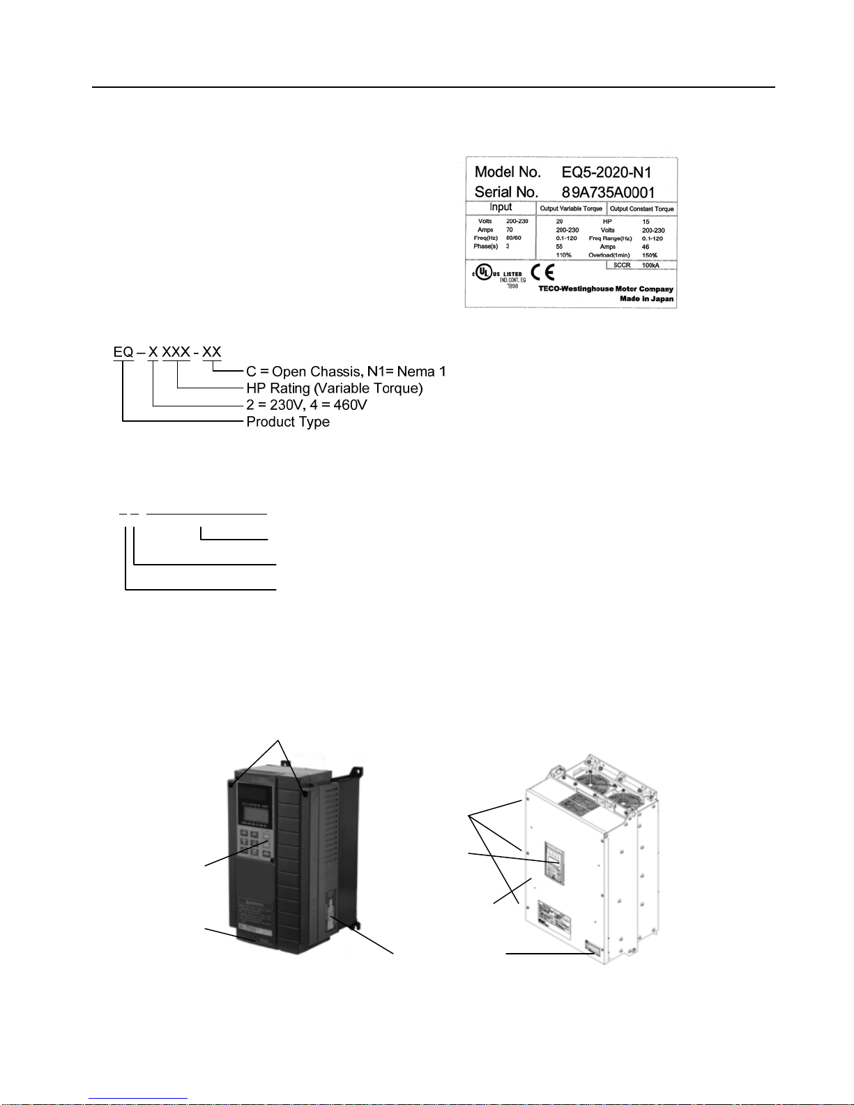
1. Check the ratings on the nameplate to confirm
that the delivered product is the one that was
ordered.
TYPE : Inverter type
SOURCE : Power rating
OUTPUT : Output rating
MASS : Mass (not indicated for products with 30HP/CT, 40HP/VT or less)
SER.No. : Serial number
8 5 XXXXXXXXXXXXX
Productionlotserialnumber
Production month:1 to 9: January to September,
X: October, Y: November, Z: December
Production year: Last digit of year (7 --> 2007)
2. Check for damaged and/or missing parts.
3. In addition to the drive unit and this manual, the package contains rubber bushings (for products of
30HP/CT, 40HP/VT or less) and a terminating resistor (1/2 W, 120) which is packed separately. The
terminating resistor for products rated 40HP/CT, 50HP/VT or more, is installed internally. The
terminating resistor is required for RS485 communication and can remain installed regardless of RS-
485 communication status.
1-2 Appearance
Mounting screws of surface cover
Digital Operator Digital Operator
Mounting screws of
surface cover
(6 screws total)
Ratings nameplate
Surface cover
Intermediate cover
Surface cover
30HP/CT, 40HP/VT or Less 40HP
/
CT, 50HP/VT or More
EQ5 AC Drive Operations Manual
_________________________________________________________________________
TECO – Westinghouse Motor Company Receiving and Handling 2
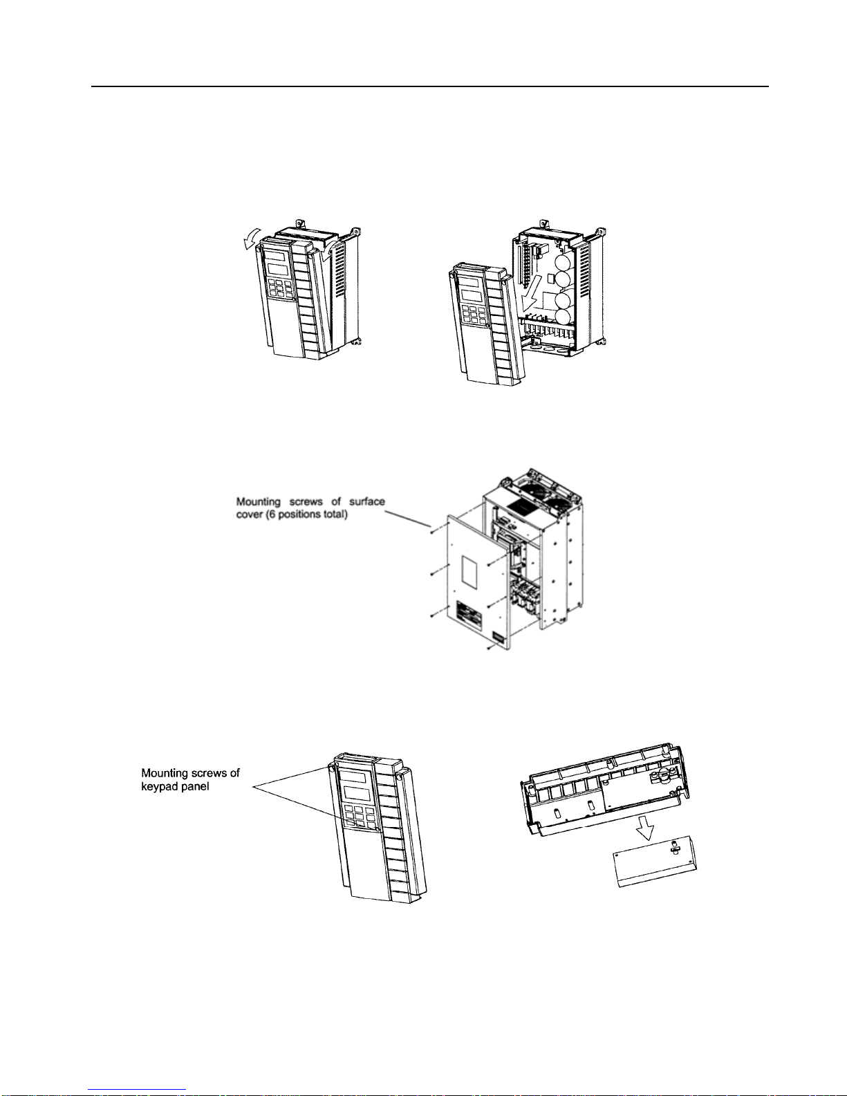
1-3 Handling the Product
1. Removing the cover
For drives rated 30HP/CT, 40HP/VT or less, loosen the mounting screws of the cover, then remove by
pulling the top (see Fig. 1.3.1).
Fig. 1-3-1 Removing the Surface Cover (for inverters rated 30HP/CT, 40HP/VT or less)
For drives of 40HP/CT, 50HP/VT or more, first remove the six mounting screws, then remove the cover
(see Fig. 1-3-2).
Fig. 1-3-2 Removing the Surface Cover (for inverters rated 40HP/CT, 50HP/VT or more)
2. Removing the digital operator
After removing the cover as explained in (1.), loosen the mounting screws of the digital operator and
remove as shown in Fig.1.3.3.
Fig. 1-3-3 Removing the Digital Operator (30HP/CT, 40HP/VT or less)
EQ5 AC Drive Operations Manual
_________________________________________________________________________
TECO – Westinghouse Motor Company Receiving, Handling, and Storage 3
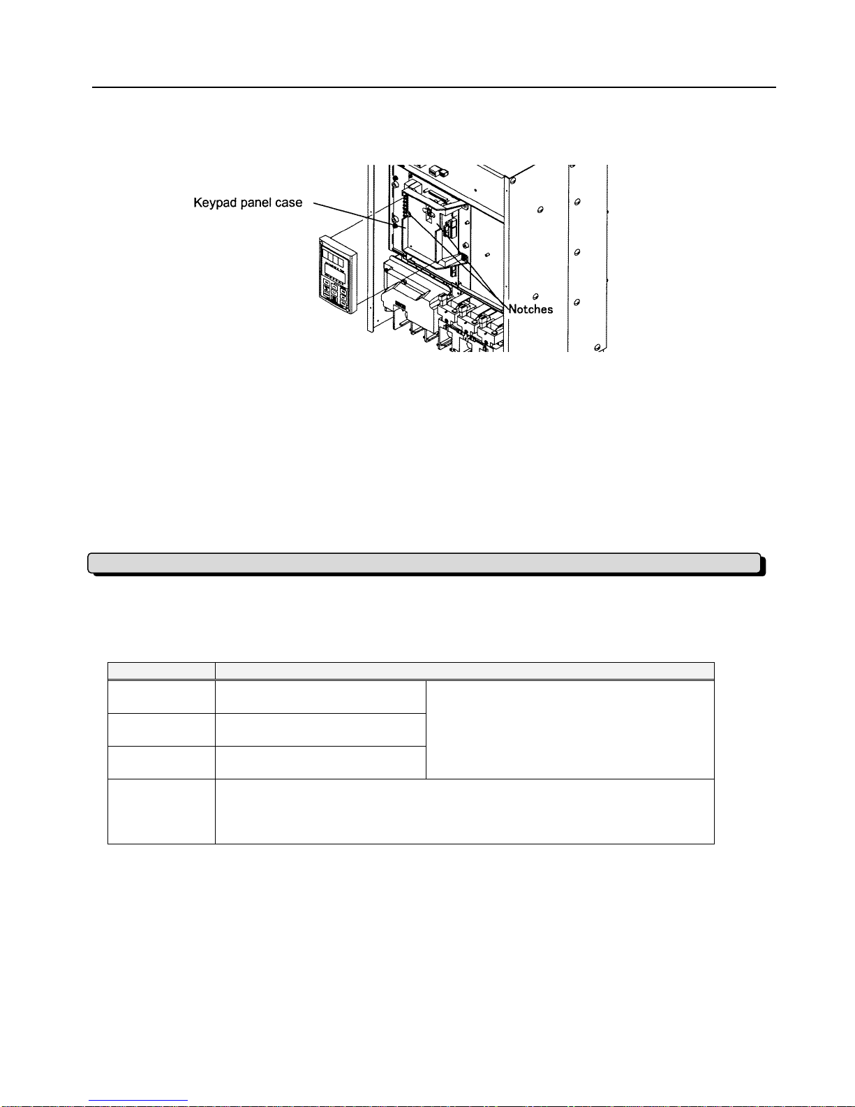
Temporary Storage
For drives 40HP/CT, 50HP/VT or more, loosen the mounting screws of the digital operator and remove
using the finger holds on the digital operator case (see Fig. 1-3-4).
Fig. 1-3-4 Removing the Digital Operator (40HP/CT, 50HP/VT or more)
1-4 Carrying and Moving the Product
1. Carry the product by the main body.
Do not carry the product while holding the cover or parts other than the main body.
2. Use a crane or hoist to carry a product equipped with handling hooks.
1-5 Storage
Temporary storage of this product must meet those conditions listed in Table 1-5-1.
Table 1-5-1 Storage Environment
Item Specifications
Ambient
temperature -10 (14°F) to +50 (122°F)
Condensation or freezing must not occur as
a result of sudden temperature changes.
Storage
temperature -25 (-13°F) to +65 (149°F)Note1
Relative
humidity 5 to 95% Note2
Atmosphere
The product must not be exposed to dust, direct sunlight, corrosive gas, oil
mist, vapor, or water. There must be a minimum salt content in the
atmosphere. Do not store where condensation may occur as a result of
sudden changes in temperature.
Note1: The storage temperature applies only to short periods of time such as when transporting
the equipment .
Note2: As a large change in temperature within this humidity range may result in condensation or freezing,
do not store where such temperature changes may occur.
1. Do not place this product directly on a floor.
2. To store the product in an extreme environment, pack in vinyl sheeting, etc.
3. If the product is stored in a high-humidity environment, insert a drying agent (e.g., silica gel)
and pack the product in vinyl sheeting.

EQ5 AC Drive Operations Manual
_________________________________________________________________________
TECO – Westinghouse Motor Company Receiving, Handling, and Storage 4
Long-term Storage
If the product is to be stored for an extended period of time after purchase, the method of storage depends
primarily on storage location.
The general long-term storage method is as follows:
1. The above conditions for temporary storage must be satisfied.
When the storage period exceeds three months, the upper limit of ambient temperature must
be reduced to 30º (86ºF) to prevent the deterioration of the electrolytic capacitors.
2. Pack the product thoroughly to eliminate exposure to moisture and include a drying agent to
ensure a relative humidity of about 70% or less.
3. If the product is mounted on equipment or a control panel and is not being unused and is exposed to
the elements such as like moisture or dust (particularly on a construction site), remove the product and
store in a suitable environment.
4. Electrolytic capacitors not provided with voltage for extended periods of time will deteriorate. Do not
store electrolytic capacitors longer than one year without providing voltage to them.
NOTES

EQ5 AC Drive Operations Manual
________________________________________________________________________
TECO – Westinghouse Motor Company Installation Environment & Method 5
2. Installation and Electrical Connections
2-1 Operating Environment
Install this product in a location that meets the conditions listed in Table 2-1-1
Table 2-1-1 Operating Environment Table 2-1-2 Output Current Reduction
Rate Based on Altitude
Item Specifications
Location Indoors Altitude Output current
reduction rate
Ambient
temperature
-10Cº to +50ºC (14ºF to 122ºF) -
For products of 30HP/CT,
40HP/VT or less, the ventilating
covers must be removed if the
ambient temperature exceeds
+40ºC (104ºF)
3300ft or lower (1000m) 1.00
3300-4950ft
(1000 to 1500m) 0.97
4950-6600ft
(1500 to 2000m) 0.95
Relative
humidity 5 to 95% non-condensing
6600-8250ft
(2000 to 2500m) 0.91
8250-9900ft
(2500 to 3000m) 0.88
Atmosphere
The product must not be exposed
to dust, direct sunlight, corrosive
gas, oil mist, vapor, or water.
There must be a minimum salt
content in the atmosphere. Do not
store where condensation may
occur as a result of sudden
changes in temperature.
Fig. 2-2-1
30HP/CT, 40HP/VT or less:
Gap X can be 0.
(side-by- side installation)
40HP/CT, 50HP/VT or more:
Gap X >= 2.0” (50mm)
Altitude 1000 m (3300 feet) or lower - For
altitudes above 1000 m (3300
feet), see Table 2-1-2.
Vibration
3mm peak from 2 to 9Hz, 9.8m/s
2
from 9 to 20Hz,
2m/s2from 20-55Hz, 1m/s2from
55 to 200Hz.
2-2 Installation Method
1. Mounting, dimensional and weight information for all of the inverter models, is covered in Sec. 8-3 of
this manual. Select the model being used and prepare the installation.
2. Securely fasten the product in a vertical upright position on a solid structure with the product
logo facing the front. Do not mount the product upside down or install in a horizontal position
as proper ventilation will be inhibited.
3. As heat is generated during inverter operation, the spaces shown in Fig. 2-2-1 are required to
ensure sufficient cooling. Since heat radiates upward, do not install the product beneath
heat sensitive equipment.
4. During operation, the heat sink may reach a temperature of 90ºC (194ºF), therefore ensure that
the material surrounding the product can withstand this temperature.
DANGER Install this product on nonflammable material such as metal.
EQ5 AC Drive Operations Manual
______________________________________________________________________
TECO – Westinghouse Motor Company Installation Method 6
5. When installing this product in a control panel,
ensure that the ventilation is sufficient to prevent the
ambient temperature of the inverter from exceeding
the specified value. Do not install the product in an
area where there is inadequate ventilation,
6. If two or more inverters must be installed in the
same equipment or control panel, arrange the units
horizontally (side by side) to minimize the effect of
heat. If two or more inverters must be installed
vertically (one on top of the other), place an
insulated plate between the inverters to minimize the
effect of heat.
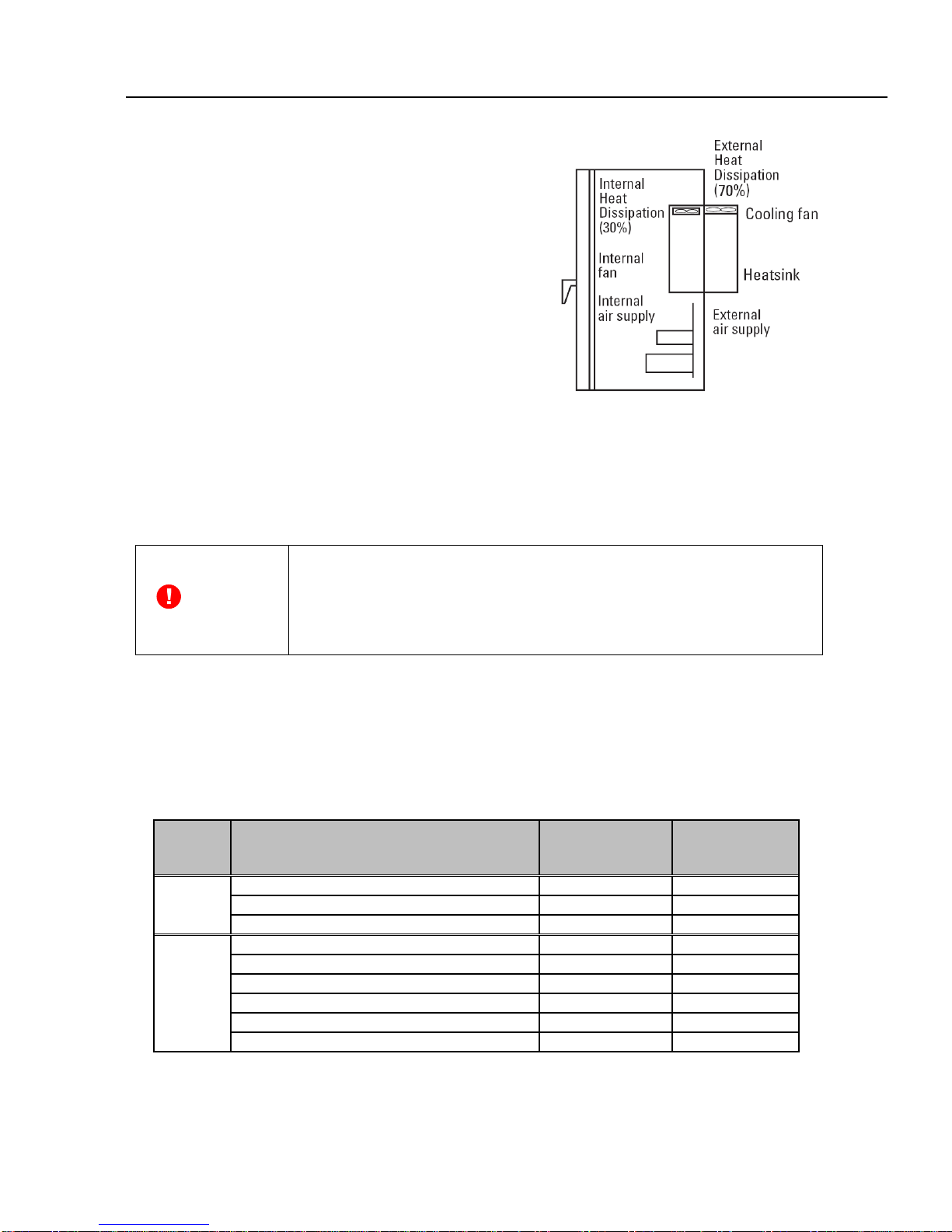
7. When shipped from the factory, inverters provide
internal cooling inside panel. An inverter of
30HP/CT, 40HP/VT or less can be converted to an
external cooling simply by adding an optional
mounting adapter.
In an external cooling system, the heat sink radiates about 70% of total inverter heat (total
loss) and can be placed outside the control panel (see Fig. 2-2-2). When doing this, ensure
that heat sink surfaces are kept free of foreign matter.
DANGER
・In the case of external cooling system, cover the back of the inverter
in order to prevent the exposure of the power capacitor and braking
resistor as electric shock may result.
・Ensure that the inverter and heat sink surfaces are kept free of
foreign matter such as lint, paper dust, small chips of wood or metal,
and dust, as
f
ire ma
y
result.
An inverter of 40HP/CT, 50HP/VT or more can be converted to an external cooling type simply by
moving
upper and lower mounting brackets as shown in Fig. 2-2-3. Remove the M6 bracket screws,
move the brackets, then secure the brackets using the M5 case mounting screws. (The
bracket screws are no longer required after changing the bracket mounting position.)
Quantity of Mounting Screws
Voltage
Series Inverter Type Bracket Screws Case
Mounting
Screws
230V EQ5 - 2040 - C to EQ5 - 2100 - C 5 (M6x20) 5 (M5x16)
EQ5 - 2125 - C 7 (M6x20) 5 (M5x16)
EQ5 - 2150 - C 6 (M6x20) 6 (M5x16)
460V
EQ5 - 4040 - C to EQ5 - 4125 - C 5 (M6x20) 5 (M5x16)
EQ5 - 4150 - C to EQ5 - 4200 - C 7 (M6x20) *1 5 (M5x16)
EQ5 - 4250 - C to EQ5 - 4300 - C 7 (M6x20) 7 (M5x16)
EQ5 - 4350 - C to EQ5 - 4400 - C 6 (M6x20) *1 6 (M5x16)
*3 EQ5 - 4450 - C to EQ5 - 4600 - C 6 (M8x20) *2
*3 EQ5 - 4150 - C to EQ5 - 4200 - C 8 (M8x20) *2
*1 Secure the brackets changing the screws, size:M5, length:20mm.
*2 Secure the brackets using the brackets screws.
Fig.2-2-2

EQ5 AC Drive Operations Manual
______________________________________________________________________
TECO – Westinghouse Motor Company Installation Method 7
*3 Do not use the bottom brackets in the bottom surface mount Installation.
Fig. 2-2-3 40HP/CT, 50HP/VT or more Removing Upper and Lower Brackets
8. For inverters of 30HP/CT, 40HP/VT or less, remove the ventilating covers if ambient temperature
exceeds +40°C (104°F)
(1) Removing the ventilating covers:
One ventilating cover is mounted on top of the inverter and the other two or three are mounted at
the bottom.
Fig. 2-2-4 30HP/CT, 40HP/VT or Less Removing Ventilating Covers

EQ5 AC Drive Operations Manual
______________________________________________________________________
TECO – Westinghouse Motor Company Electrical Connections 8
2-3 Electrical Connections
To access the terminal blocks remove the cover in accordance with the instructions in this manual.
2-3-1 Basic Power Electrical Connections
1. Always connect input power to the main circuit power terminals L1/R, L2/S, and L3/T
of the inverter. Check that the input voltage to be applied is within the maximum allowable
voltage marked on the nameplate.
2. Always connect the power output terminals U, V, and W to the motor. Check that output
voltage rating is correct for the motor being used.
DANGER- Do not connect the input voltage to the motor terminals U, V, and W as
extreme damage and / or injury may result.
3. Using the proper wire size and type, always bond the ground terminal to a reliable ground
connection to prevent dangerous situations such as the possibility of fire or electrical shock
and to minimize electrical noise.
4. Use a secure reliable cable crimp connection between the terminal and a cable.
5. After terminating the wiring connection, ensure the following:
a. The connection is correct.
b. All necessary connections have been made.
c. There is no short-circuit or ground fault between terminals and cables.
6. If a wiring change needs to be made after power-up, wait at least 5 minutes before making
any wiring changes. Also ensure that the charge indicating LED is off. This is necessary
because the DC power section capacitor(s) does not discharge immediately after power-down
and maintains lethal voltages. The actual DC voltage may also be checked with a multimeter
and should be 25VDC or less. If short circuiting the DC voltage after power-down, sparks
may occur.
DANGER
•Always properly ground the inverter otherwise electric shock or fire
may result.
•Ensure that a licensed specialist performs all wiring and that all codes
are met.
•Confirm that the power is turned off and that the charge indicator is off
(Wait 5 minutes for 30HP/CT, 40HP/VT and less, 10 minutes for
40HP/CT, 50HP/VT or above) before removing any protective covers as
lethal voltages are present and electrical shock may result.
NOTES

EQ5 AC Drive Operations Manual
______________________________________________________________________
TECO – Westinghouse Motor Company Basic Wiring Diagram 9
EQ5 AC Drive Operations Manual
______________________________________________________________________
TECO – Westinghouse Motor Company Power Terminal Designations & Wiring 10
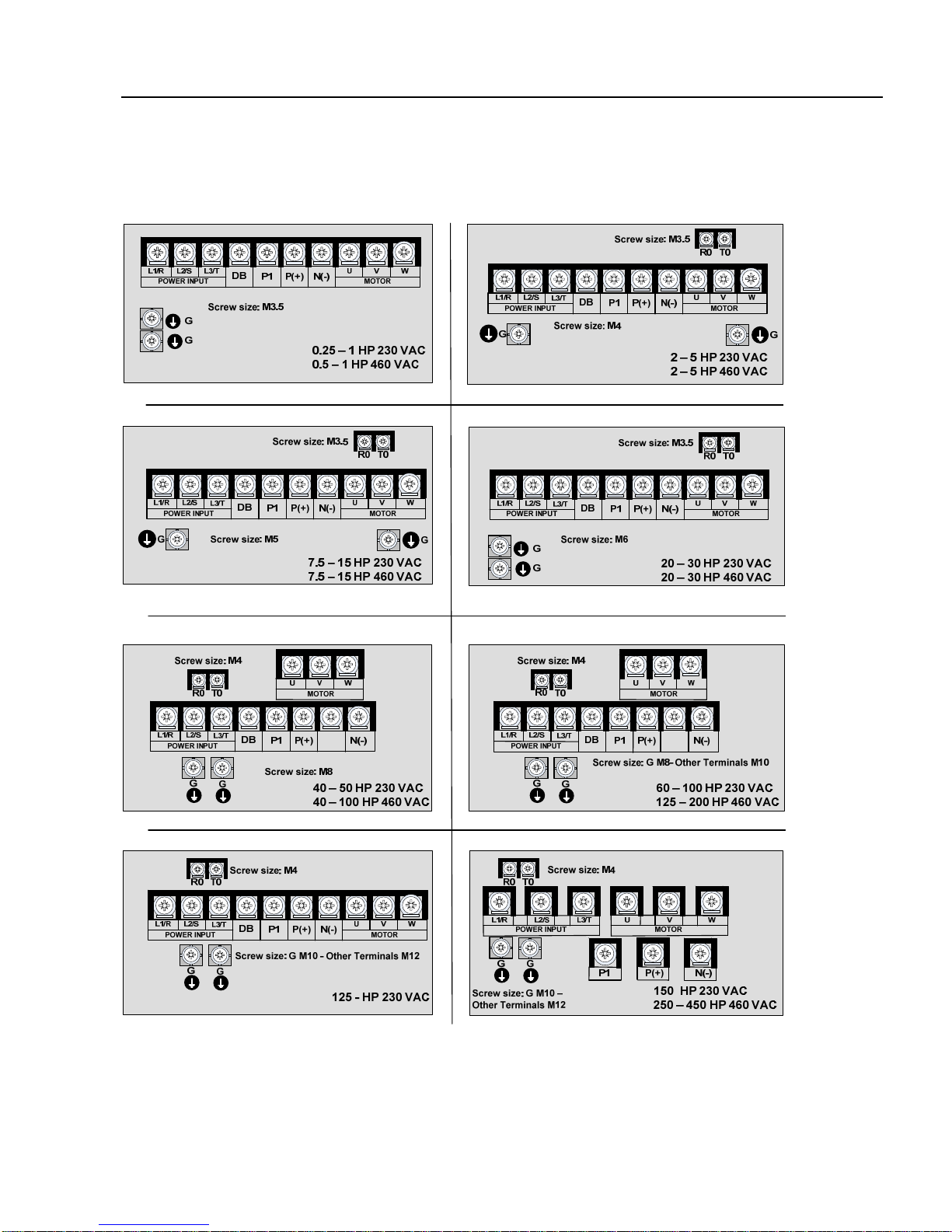
2-3-2 Connecting the Input Power, Motor Output Power, and Ground Terminals
The following shows the terminal arrangements for the various HP ranges of the EQ5.
The terminal screw sizes are also shown for reference.

EQ5 AC Drive Operations Manual
______________________________________________________________________
TECO – Westinghouse Motor Company Power Terminal Designations & Wiring 11
R0 T0
GG
L1/R L2/S L3/T
POWER INPUT
L1/R L2/S L3/T
UVW
MOTOR
UVW
P1
P1
P(+) P(+)
N(-) N(-)
Screw size: M4
Screw size: G M10 –
Other Terminals M12
500 – 600 HP 460 VAC
R0 T0
GG
L1/R L2/S L3/T
POWER INPUT
L1/R L2/S L3/T
UVW
MOTOR
UVW
P1
P1 P(+)
P(+)
N(-)
N(-)
Screw size: M4
Screw size: G M10 –
Other Terminals M12
700 – 800 HP 460 VAC
Table 2-3-1 Functions of Main Circuit Terminals and Ground Terminals
Symbol Terminal Name Description
L1/R, L2/S, L3/T Main circuit input power
terminals. Connects to a 3-phase power supply.
U, V, W Inverter output terminals Connects to a 3-phase motor.
R0, T0 Auxiliary control-power
input terminals.
Connects a backup AC power supply to the
control circuit. (Not applicable to inverters
of 1HP or less)
P1, P (+) DC link reactor terminal
connection. Connects a power-factor correcting DC link
reactor. (optional)
P (+), DB External braking resistor
terminal connections. Connects an external braking resistor for
inverters 10HP/CT, 15HP/VT or less.
P (+), N (-) DC link circuit terminals Supplies DC link voltage to the external
braking or power regeneration unit
(optional).
G Inverter ground terminal Inverter chassis (case) ground.
1.Main circuit input power terminals (L1/R, L2/S, L3/T)
a. For circuit (wiring) protection, connect these terminals to the input power supply using a
molded-case circuit breaker or a ground-fault circuit interrupter. Phase-sequence
matching is unnecessary.
b. To ensure safety, a magnetic contactor should be connected to disconnect the inverter
from the input power supply when the inverter protective function activates.
c. The main circuit input power should be used to start or stop the inverter only if absolutely
necessary and then should not be used more than once every hour.
d. If you need to connect these terminals to a single-phase power supply, please consult
the factory.
EQ5 AC Drive Operations Manual
______________________________________________________________________
TECO – Westinghouse Motor Company Power Terminal Designations & Wiring 12
2. Inverter output terminals (U, V, W)
a. Connect these terminals to a 3-phase motor in the correct phase sequence. If the
direction of motor rotation is incorrect, swap any two of the U, V, and W phases.
b. Do not connect a power factor correction capacitor or surge suppressor to the inverter
output.
c. If the cable from the inverter to the motor is excessively long, a high-frequency current
can be generated by stray capacitance between the cables and result in an overcurrent
trip of the inverter, an increase in leakage current, or a reduction in current indication
precision.
d. When a motor is driven by a PWM-type inverter, the motor terminals may be subject to
surge voltage generated by PWM switching. If the motor cables are excessively long,
particularly the 460V series units, the surge voltage will deteriorate motor insulation
over time. To prevent this, use the following guidelines:
Inverters 7.5HP/CT, 10HP/VT and Higher
Motor Insulation Rating 1000V 1300V 1600V
460 VAC Input Voltage 66 ft (20 m) 328 ft (100 m) 1312 ft (400 m) *
230 VAC Input Voltage 1312 ft (400 m) * 1312 ft (400 m) * 1312 ft (400 m) *
Inverters 5HP/CT/VT and Smaller
Motor Insulation Rating 1000V 1300V 1600V
460 VAC Input Voltage 66 ft (20 m) 165 ft (50 m) * 165 ft (50 m) *
230 VAC Input Voltage 328 ft (100 m) * 328 ft (100 m) * 328 ft (100 m) *
* In this case the cable length is determined by secondary effects and not voltage
spiking.
Note: When a motor protective thermal O/L relay is inserted between the inverter and the motor, the
thermal O/L relay may malfunction (particularly in the 460V series units), even when the cable length
is 165 feet (50m) or less. To correct this, insert a filter or reduce the PWM carrier frequency. (Use
function code “F26 Motor sound”.)
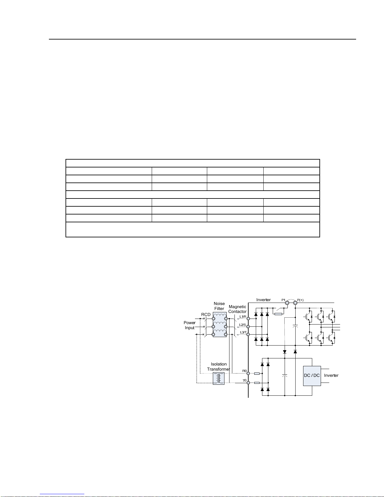
3. Auxiliary control-power input terminals (R0 and T0)
The inverter will operate even if power
is not provided to these terminals. If a
protective circuit is activated and the
magnetic contactor on the inverter
power input side is opened (off), the
inverter control circuit power, the alarm
output (30A, B, and C), and the keypad
display will lose power. To prevent this,
the same AC power as supplied to the
main input circuit must be supplied (as
auxiliary control power) to the auxiliary
control - power input terminals (R0 and
T0). (see Fig. 2-3-2)
a.To ensure effective noise reduction
when using an input noise filter, the
output from the filter must go to
the auxiliary control-power input
terminals. If these terminals are
Fig. 2-3-2 Connecting the Auxiliary Control-Power
Input Terminals
connected to the input side of the filter, the noise reduction is much less effective.

EQ5 AC Drive Operations Manual
______________________________________________________________________
TECO – Westinghouse Motor Company Power Terminal Designations & Wiring 13
b. When the RCD (Residual-current Protective Device) is installed (30HP/CT, 40HP/VT or less), the
terminal R0
and T0 should be connected to the output side of the RCD. If they are connected to the input side,
the RCD will malfunction because the power supply of the inverter is three phase and the
R0 and T0 input is single phase. If it is required to connect terminals R0 and T0 are to the input side
of the RCD, an isolation transformer is required as shown on the Fig. 2-3-2.
4. Connecting a DC link choke to terminals (P1 and P (+))
a. Before connecting a DC link choke to these terminals, remove the
factory-installed jumper. (Fig. 2-3-3)
b. If a DC link choke is not used, do not remove the jumper.
Note: For inverters of 100HP or more, the DC link choke is provided
as separate standard component and should always be
connected. For inverters less than 100 HP, the DC link choke
is not provided and is optional.
P(+)P1 X
DC Link Choke
Inverter
Fig. 2-3-3 Remove Jumper
4. Connecting an external braking-resistor to terminals (P (+) and DB) (10HP/CT, 15HP/VT or less)
(Fig. 2-3-4). For inverters 10HP/CT, 15HP/VT or less, a built-in braking resistor is connected to
terminals P (+) and DB. If this braking resistor does not provide sufficient thermal capacity (e.g.
high operating duty cycle or high inertia loads), an optional external braking resistor must be
installed to improve braking performance.
a. Remove the internal braking resistor from
terminals P(+) and DB and Insulate the
terminals with adhesive insulation tape, etc.
b. Connect terminals P(+) and DB of the external
braking resistor to terminals P(+) and DB of the
inverter.
c. The wiring (cables twisted or otherwise) should
not exceed 16ft (5m).
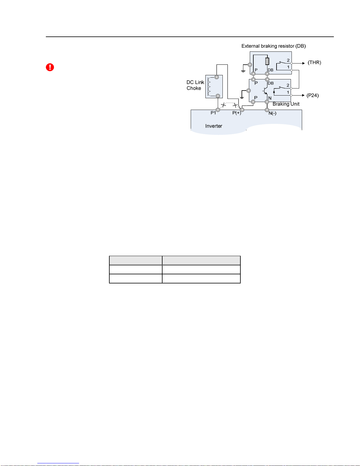
6. DC link circuit terminals (P (+) and N (-)) (Fig.2-3-5).
The EQ5 inverter of 15HP/CT, 20HP/VT or more
does not contain a drive circuit for the braking
resistor. To improve braking performance, an optional
external braking unit and external braking resistor
must be installed.
Fig. 2-3-4 Connection (10HP/CT,
15HP/VT or less)
a. Connect terminals P and N of the braking unit to terminals P(+) and N(-) of the inverter.
The wiring (cables twisted or otherwise) should not exceed 16ft(5m).
b. Connect terminals P and DB of the braking resistor to terminals P and DB of the braking
unit. The wiring (cables twisted or otherwise) should not exceed 33ft (10m).
c. Connect terminals P and DB of the braking
resistor to terminals P and DB of the
braking unit. The wiring (cables twisted or
otherwise) should not exceed 33ft (10m).
EQ5 AC Drive Operations Manual
______________________________________________________________________
TECO – Westinghouse Motor Company Power Terminal Designations & Wiring 14
DANGER- When terminals P (+) and N (-) of
the inverter are not used, leave terminals
open. If P(+) is connected to N (-) the bus
voltage will be shorted, or if braking resistor is
connected directly, the resistor can cause
fire.
d. Auxiliary contacts 1 and 2 of the braking
unit are polarity sensitive. To connect the
braking unit, refer to the "TECO Inverter
Speecon Braking Unit Manual”.
Fig. 2-3-5 Connection (15HP or more)
7. Inverter ground terminal
To ensure safety and noise reduction, always bond the inverter ground terminal. Also,
metal frames of electrical equipment must be grounded as specified in applicable codes
The connection procedure is as follows:
a. Ground all metal frames and chassis to a ground terminal (Ground resistance: 10).
b. In accordance with applicable codes, use a suitable ground cable to connect the inverter
system to ground.
8. Placement of connector (CN UX) for inverters 40HP/CT, 50HP/VT and higher.
When an inverter of 40HP or higher is connected to an input voltage listed in Table 2-3-2,
disconnect the auxiliary power connector CN UX from U1 and connect to U2.
(Refer to Fig. 2-3-7)
Table 2-3-2 Main Input Voltage Requiring Auxiliary Power Connector Change
Frequency [Hz] Input voltage range [VAC]
50 380 - 398
60 380 - 430
9. Placement of fan power connector (CN RXTX) for inverters 40HP/CT, 50HP/VT or higher.
An inverter of 40HP/CT, 50HP/VT or greater uses an AC cooling fan. When the inverter is being
operated with DC Input power, the fan must still be energized from an AC power
source. To do this, position the fan connector (CN RTXT) as shown in Fig. 2-3-9
and provide AC voltage to auxiliary input terminals R0 and T0. For the (CN RTXT)
connector placement method, see Fig. 2-3-7.
Note: When shipped, the fan connector (CN RXTX) is connected to L1/R-L3/T. Do not change the
connector position unless DC power is being used.
This manual suits for next models
1
Table of contents
Popular Controllers manuals by other brands

Firefly
Firefly FF-211 Important Instructions and Specifications

TRIAC
TRIAC THD S09 SERIES Installation & maintenance manual

Middle Atlantic Products
Middle Atlantic Products FC Series instruction sheet

Triconex
Triconex Trident Planning and installation guide

Seltron
Seltron KXD10B manual

Niagara
Niagara Edge-10 installation guide


