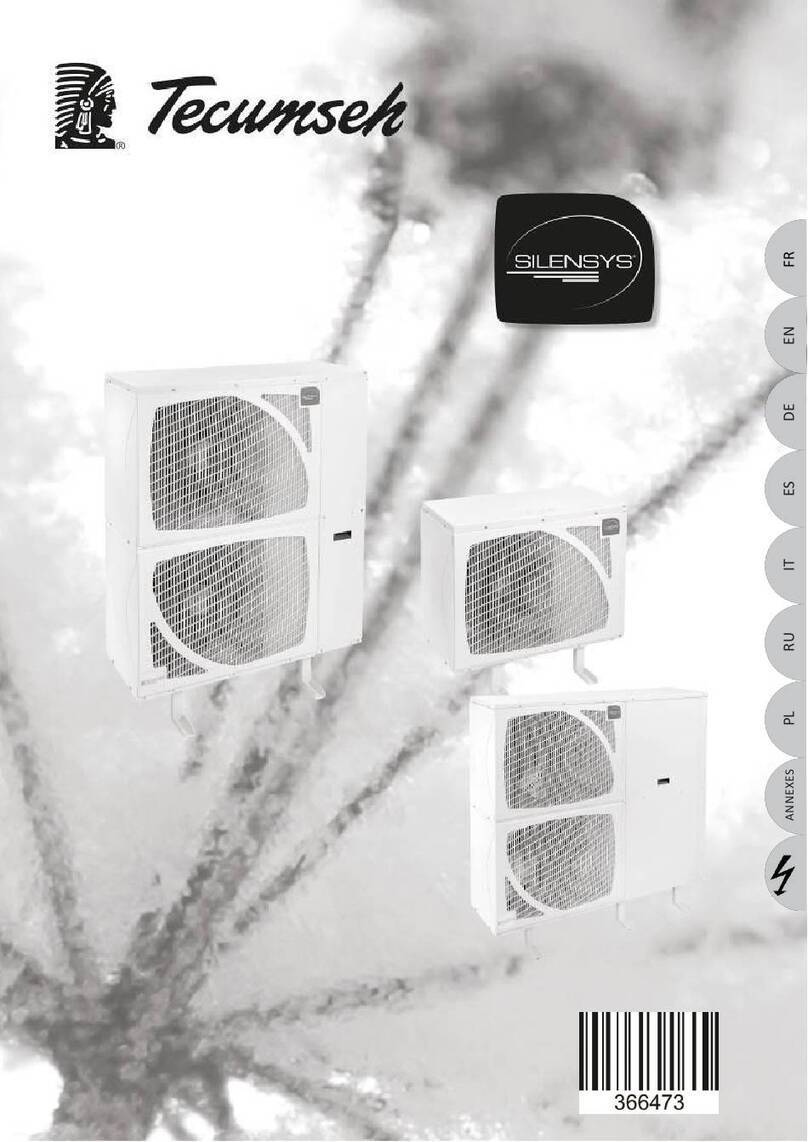
Tecumseh INFINEE AC25U Instruction Manual

INSTALLATION AND MAINTENANCE
MANUALMANUEL D'INSTALLATION ET DE
MAINTENANCE
INSTRUKCJA MONTAŻU IKONSERWACJI
INFINEE
Water chillers
Groupes d'eau Glacée
Agregaty wody lodowej
ENGLISH……….…………………………………………..... PAGE 3
FRANÇAIS (ORIGINALE)…………………………..……... PAGE 36
POLSKI…………………………..……............................. STRONA 70


TECUMSEH EUROPE S&L
2 av. Blaise Pascal, 38090 Vaulx Milieu
Tel.: +33 (0)4 74 82 24 00 - www.tecumseh.com
ENGLISH 3
Version: 2020-01
Table of contents
Warning .......................................................................................................................................... 5
Technical characteristics.............................................................................................................. 7
General description of the machine .................................................................................... 7
Identification plate................................................................................................................. 7
Safety devices........................................................................................................................ 8
Schematic diagrams.............................................................................................................. 9
Dimensions and weight ........................................................................................................ 9
Installation.................................................................................................................................... 11
Unpacking ............................................................................................................................ 11
Handling ............................................................................................................................... 11
Choice of location ............................................................................................................... 12
Sound.................................................................................................................................... 14
Fixing .................................................................................................................................... 14
Freeze protection................................................................................................................. 14
Hydraulic connection.......................................................................................................... 15
Electrical connection .......................................................................................................... 16
Protection of the pump from cavitation ............................................................................ 17
Terms of use ........................................................................................................................ 17
Commissioning............................................................................................................................ 18
Pump characteristics .......................................................................................................... 19
Characteristic of the chiller hydraulic circuit ................................................................... 20
Control.......................................................................................................................................... 22
Servicing - Maintenance ............................................................................................................. 22
Circuit sealing...................................................................................................................... 22
Vacuum pumping ................................................................................................................ 22
Refrigerant charge............................................................................................................... 23
Condenser............................................................................................................................ 24
Hydraulic pump ................................................................................................................... 24
Air filter................................................................................................................................. 25
Replacing the fan................................................................................................................. 25
Replacing the compressor ................................................................................................. 26
Look for leaks and carry out periodic checks.................................................................. 27
Electrical check ................................................................................................................... 27
Dryer ..................................................................................................................................... 27
Glycol.................................................................................................................................... 27
Strainer................................................................................................................................. 28

TECUMSEH EUROPE S&L
2 av. Blaise Pascal, 38090 Vaulx Milieu
Tel.: +33 (0)4 74 82 24 00 - www.tecumseh.com
ENGLISH 4
Version: 2020-01
Properties of R290 Propane ............................................................................................... 29
Technical features....................................................................................................................... 30
Performance: ambient temperature 15°C.......................................................................... 30
Performance: ambient temperature 32°C.......................................................................... 31
Performances : ambient temperature 35°C....................................................................... 32
Performance: ambient temperature 46°C.......................................................................... 33
Operating range................................................................................................................... 34
Warranty....................................................................................................................................... 34

Installation and maintenance manual
INFINEE chillers
TECUMSEH EUROPE S&L
2 av. Blaise Pascal, 38090 Vaulx Milieu
Tel.: +33 (0)4 74 82 24 00 - www.tecumseh.com
ENGLISH 5
Version: 2020-01
Warning
Obligation to be familiar with this document
It is essential to understand and apply the instructions contained in this document before
beginning installation.
Information relating to the delivery of the chillers
For information relating to delivery of the chillers, refer to the "General Terms of Sale".
Chiller transport
Chillers must be transported and handled according to the instructions noted in this manual. Any
unpacking, transport, manipulation and handling must be carried out by qualified personnel in
compliance with standards and hygiene and safety regulations in force in the country concerned.
Ditto for the protection of personnel involved, and any additional regulations referring to it.
Chiller installation
Installation of this chiller and related equipment must be performed by qualified personnel.
Installation of this chiller must be designed, built, put into service, and operated in the state of the
art, according to the local regulations in force on the site and in the country (safety, hygiene
regulations etc.)
For the installation of this chiller, companies like all staff must have the skills, training,
authorisation, the skills necessary for the smooth running of operations in accordance with local
regulations in force. This may include operations as varied as the study, design, connection piping
(welding, soldering), electrics etc.
We draw your attention to the fact that a refrigeration system requires expertise and must be built
in the state of the art. The knowledge and application of local and national regulations is essential.
For operations not described or included in this manual, consult your Tecumseh representative.
In addition to skills and authorisation, staff will be equipped with all the necessary individual
protection, such as glasses, gloves, safety shoes, etc.
Comply with the standards in force in the country where the chiller is installed and the rules of the
art for refrigeration and electrical connections.
Responsibility
TECUMSEH EUROPE S.A. cannot be held responsible if installation and maintenance are not in
line with the instructions provided in this manual. Therefore, users should apply the instructions
contained in this document. They must also take into account the technical and regulatory
characteristics related to the installation site, the local regulations in force as well as design,
execution and operation in the rules of art.
Risk of ignition and explosion
Attention DANGER: This product contains refrigerant R290 (propane). This refrigerant is
flammable and explosive. It must only be handled by qualified personnel. See warning above.
Location of the product
Do not install the product in a corrosive, explosive, atmosphere, close to source of heat, or any
environment that may adversely affect the proper operation of the chiller and in accordance with
the regulations.

Installation and maintenance manual
INFINEE chillers
TECUMSEH EUROPE S&L
2 av. Blaise Pascal, 38090 Vaulx Milieu
Tel.: +33 (0)4 74 82 24 00 - www.tecumseh.com
ENGLISH 6
Version: 2020-01
Automatic restart
After a voluntary or involuntary power failure, this product will be able to restart autonomously.
Capacitor charge risk
Caution: Since this product is equipped with capacitors, it is essential not to intervene without
having checked the absence of voltage, even after disconnection of the disconnector, in order to
avoid an electric shock by the discharge of one of the capacitors (ex inverters)
Bans
It is prohibited:
•To disconnect the security organs
•To service the chiller without having correctly mounted all the appropriate protections.
•To operate electricity without having turned off the power on the product and made a
consignment.
•To operate this product out of the operating ranges planned and defined for this product
in Paragraph 7.4 operating range.
•To walk on the product or on the entry and exit of water pipes.
•To clean the machine with a water jet or a high-pressure cleaner.

Installation and maintenance manual
INFINEE chillers
TECUMSEH EUROPE S&L
2 av. Blaise Pascal, 38090 Vaulx Milieu
Tel.: +33 (0)4 74 82 24 00 - www.tecumseh.com
ENGLISH 7
Version: 2020-01
Technical characteristics
General description of the machine
The air/water chiller is composed of an air condenser, which yields heat to the ambient air. The evaporator
is a plate heat exchanger, which takes calories to water. A pump circulates the water in the circuit and
feeds the emitters at the temperature desired by the customer. This temperature is adjustable either at
the start or in return to the chiller.
The chiller uses a natural fluid, the R290 propane, which has very little impact on the planet GWP 3.
The chiller has an inverter on the compressor and a second one on the water pump; it is able to adapt its
power depending on the temperature of the water and its delta T.
Identification plate
The data plate of the chiller range includes the following information
The description of the product
The product code
Maximum intensity
Refrigerant fluid used (symbol of flammability)
Amount of refrigerant fluid in Kg
CE mark, identification number of the notified body
Serial number (manufacturing year, day, time)
PSHP: Maximum allowable pressure on the high pressure side
PSBP: Maximum allowable pressure on the low pressure side
Check on the chiller receipt that the information corresponds to the ordered product

Installation and maintenance manual
INFINEE chillers
TECUMSEH EUROPE S&L
2 av. Blaise Pascal, 38090 Vaulx Milieu
Tel.: +33 (0)4 74 82 24 00 - www.tecumseh.com
ENGLISH 8
Version: 2020-01
Safety devices
The chiller is equipped with a high-pressure pressure switch. Their function is to protect the chiller in case
of high pressure increase (if the condenser is dirty, for example).
HP and LP safety valves
The presence of safety valves on the low and high pressure sides of the refrigerant circuit ensure
the protection of the chiller against any abnormal rise in pressure or exposure to external factors
(fire, abnormal source of heat, etc.). This device is intended to prevent the explosion of a
component of the circuit.
If the valve is triggered, the R290 is discharged outside the chiller (see diagram in Paragraph II-
4). Under no circumstances should the valve outlets be obstructed. Depending on the final
location, the installer must take appropriate security measures according to local and national
regulations.
Note that the chiller is classified according to EN378-1 as a closed ventilated indirect system. The
installer must integrate, on the water side, relief valves to de-gas the propane in case of
penetration of the latter in the water circuit. See Diagram (below)
Diagram:
ATEX
The compartment around the compressor is of type ZONE 2 (ATEX). It is essential that staff be
informed, trained and qualified. It is necessary to follow the local and national regulations of the
country in which this product is installed (installation, maintenance, etc.).
PED classification
Considering the PED ((Pressure Equipment Directive), the chiller is classified in Category II. It is
essential to follow European and local regulations of the country in which this product is installed
(installation, maintenance, etc.).
Occupied space
Section containing
R290 refrigerant

Installation and maintenance manual
INFINEE chillers
TECUMSEH EUROPE S&L
2 av. Blaise Pascal, 38090 Vaulx Milieu
Tel.: +33 (0)4 74 82 24 00 - www.tecumseh.com
ENGLISH 9
Version: 2020-01
Schematic diagrams
Rep.
Designation
Rep.
Designation
A
SH4610U compressor
I
Liquid vapour exchanger
B
HP R290 pressure switch
J
R290 5/8" electronic expansion valve
C
HP 1 pressure sensor
K
Plate Evaporator
D
B500 condenser
L
LP 1 pressure sensor
E
Liquid receiver
M
LP safety valve
F
HP safety valve
N
LP 2 pressure sensor
G
R290 5/8" filter dryer
O
LP R290 pressure switch
H
R290 5/8" Sigh glass
Dimensions and weight
INFINEE R290 chiller
AC25U
Length (mm)
1686
Width (mm)
924
Height (mm)
1541
Net weight (kg)
Gross weight (kg)
450
500

Installation and maintenance manual
INFINEE chillers
TECUMSEH EUROPE S&L
2 av. Blaise Pascal, 38090 Vaulx Milieu
Tel.: +33 (0)4 74 82 24 00 - www.tecumseh.com
ENGLISH 10
Version: 2020-01
Gravity axis

Installation and maintenance manual
INFINEE chillers
TECUMSEH EUROPE S&L
2 av. Blaise Pascal, 38090 Vaulx Milieu
Tel.: +33 (0)4 74 82 24 00 - www.tecumseh.com
ENGLISH 11
Version: 2020-01
Installation
Unpacking
Before unpacking, check the external condition and the absence of signs of shock or deformation on the
packaging.
Handling
The packaging permits the handling of the chiller by a forklift or a pallet jack. It is advisable to keep the
packaging to the place of installation.
The chiller can be handled and lifted either by a forklift or slings (in good condition and that can support
the load).
Any manipulation or handling must be carried out by one (or more) specialised handling company or
trained and authorised personnel for this purpose, using the appropriate equipment and in good standing.
It is necessary to follow the information shown in the diagram below.
The product should not be dragged on the ground.
As indicated in the diagrams below, wrap each strap in the stringers located at the ends of the chiller for
greater stability. The straps in the stringers also allow a stop in transition and secure the handling. Then,
it is necessary to bring together the straps above the product and check the stability and quality of your
fixing points by lifting the product off the ground. This check must be made at low height (10 to 15 cm
from the ground).
Diagrams:
2 x
5 m mini

Installation and maintenance manual
INFINEE chillers
TECUMSEH EUROPE S&L
2 av. Blaise Pascal, 38090 Vaulx Milieu
Tel.: +33 (0)4 74 82 24 00 - www.tecumseh.com
ENGLISH 12
Version: 2020-01
Choice of location
The chiller must only be installed outside in a clear, free space, with continuous renewal of air.
The refrigerant fluid present in the chiller is R290 (propane), which is heavier than air (higher
density). For these reasons, it should be positioned above the ground to avoid any pocket
formation of R290.
Access to the chiller should only be possible for authorised people, who have been informed of
the following points: General and special security measures and the information contained in this
manual.
The chiller should be installed and placed so that no leakage of refrigerant fluid can enter the
building or endanger people and property. The refrigerant fluid must not be able to spread in an
air duct, under a door, a hatch or a similar opening in case of leakage.
In the case of a shelter intended for refrigeration equipment located in the open air, this shelter
must be fitted with a ventilation device adapted to a propane chiller.
Once installed, the chiller should not block or hinder any passages, the movement of people or the
opening of doors.
Respect the distances between the chiller and the obstacles surrounding it to ensure good air circulation.
Refer to the implementation diagram proposed below.
The surface supporting the chiller must be flat, level, scaled and strong enough to support the weight of
the chiller and vibrations. The chiller must be mounted level
The chiller should be installed in a place that is well ventilated and not subject to prevailing winds. The air
flow to the condenser under the compressor, in the foot stringers, must be free and permanent. No frontal
or lateral obstacle must disrupt the air flow or cause any type of air recirculation to the condenser or bad
ventilation of the electrical cabinet.
This will prevent, among other things, an abnormally high condensation temperature.
For chillers installed at high altitude, it is necessary to consider the effect of air density.

Installation and maintenance manual
INFINEE chillers
TECUMSEH EUROPE S&L
2 av. Blaise Pascal, 38090 Vaulx Milieu
Tel.: +33 (0)4 74 82 24 00 - www.tecumseh.com
ENGLISH 13
Version: 2020-01
Installation diagram:
* : Can be reduced if the recirculation of air is avoided. The minimum distance is 1000 mm to allow
access for maintenance and subject to avoiding any recycling of air.
Air flow
*

Installation and maintenance manual
INFINEE chillers
TECUMSEH EUROPE S&L
2 av. Blaise Pascal, 38090 Vaulx Milieu
Tel.: +33 (0)4 74 82 24 00 - www.tecumseh.com
ENGLISH 14
Version: 2020-01
Sound
The chiller is designed for quiet operation. Nevertheless, the choice of location should take into
consideration possible discomfort for the neighbourhood and regulations in force.
Precautions must be taken during the study, design and realisation of the installation not to generate noise
or vibration, etc.
Compressor power frequency
Hz
25
40
50
75
85
Sound power level
Lw dBA
78.6
80.2
83.2
85.9
88.1
Pressure level at 10 m *
Lp dBA
58.6
60.0
63.0
65.1
66
* in free field on a reverberant plane
Fixing
The chiller must be installed and securely fixed to a stable, level plane.
Arrange a base capable of supporting the load and vibrations.
The brackets must be sealed with means adapted to the soil quality.
Use dowels suitable for the materials used and a proper sealing length. Do not use a wooden rafter as a
fixing sleeper.
It is recommended to separate (in terms of vibration) the chiller from its support and the support of the
ground or the wall, thanks to joints in absorbing materials or antivibration pads (not provided). In this case,
comply with the manufacturers’ recommendations for their selection and implementations. The selection
of shock absorbers and their absorption capacity are not the responsibility of TECUMSEH.
The chiller must be installed level (+/- 0.5%).
Under no circumstances should acoustic cladding be installed on the compressor or the chiller.
Freeze protection
Components such as the evaporator, the pump and the pipes can be damaged by frost. It is necessary
to integrate antifreeze protection according to the temperature of the water and its location (meteorological
condition, prevailing winds, exposure, etc.). The temperature of the chiller coolant can be regulated down
to -8°C. Refer to the Section “Glycol” to determine the appropriate minimum protection
In normal operation the hydraulic pump works continuously and mounting on the installation of a by-pass
valve (diagram below) is essential at the minimum.
Diagram:
The chiller has a specific algorithm that protects the hydraulic system in case of negative
temperature and chiller shutdown. It is imperative to maintain water flow in the chiller. Indeed,
according to the temperature level, the pump will be started and stopped at regular time intervals. If
the water temperature continues to drop and reach a very low level, then the pump will be operated
continuously. In these two cases, cold production is stopped.
Open bypass
Valves

Installation and maintenance manual
INFINEE chillers
TECUMSEH EUROPE S&L
2 av. Blaise Pascal, 38090 Vaulx Milieu
Tel.: +33 (0)4 74 82 24 00 - www.tecumseh.com
ENGLISH 15
Version: 2020-01
Hydraulic connection
A safety valve must be added by the installer to the coolant circuit (hydraulic circuit).
The regulations require the installer, on the coolant network, to set up a degassing safety device
appropriate for the R290 (propane). The goal is to prevent R290 from entering or spreading in a
public or confined space or otherwise.
Use flexible couplings (adapted to the operating system) to reduce vibration transmission.
Thermally insulate the piping to reduce the condensation and heat loss.
Insulation must be implemented continuously to avoid any thermal bridge that can generate problems of
condensation and corrosion.
The thickness and insulating materials must be selected according to location, installation, operating
temperature and maximum ambient temperature to avoid any risk of condensation,
Depending on the installation circumstances, mechanical protection, anti UV or wind protection (for
example) is recommended.
When filling with glycolated water and before operating the pump, it is necessary to purge air from the
system. Use different steam traps available in the chiller hydraulic system. The complete installation must
be designed, built and fitted with air purge points at the highest point of the circuit. (See Section 4
Commissioning).
Hydraulic connection
Hydraulic connection
Hand valve
Hand valve
Not supplied
To be installed on water loop
Medium pressure
Sensor
Strainer
Pump
Low pressure
Sensor
Bypass
Electrovalve
Degasser
Evaporator

Installation and maintenance manual
INFINEE chillers
TECUMSEH EUROPE S&L
2 av. Blaise Pascal, 38090 Vaulx Milieu
Tel.: +33 (0)4 74 82 24 00 - www.tecumseh.com
ENGLISH 16
Version: 2020-01
The figure below indicates the junction points and the diameters of connections.
Install drain valves at the lowest points of the circuit
Diagram:
BS valves G1’1/2 (40/49)
Use PTFE tape, an adhesive, or fibre or
rubber joints to seal according to the type
of connection. Oakum is formally
prohibited.
Electrical connection
Any electrical work (connection, wiring etc.) should be performed with the power off and by
authorised personnel.
If the cable is damaged, it must be replaced.
All wiring on site must be consistent with the standard NF C15-100 in France or the legal standards in
force in the country concerned (for example IEC 60204/IEC 60335). It is recommended to make a different
and separate cable pass from the refrigerant and hydraulic pipe passages. Similarly, it is recommended
to separate the electrical cables of power, control, signalling and communication.
The chiller’s supply voltage is three-phase + neutral 400V 50 Hz. The sizing of the connection cables
(power, control) is the installer’s responsibility. This must take into account, in addition to the information
on the data plate, the regulations of the country where the product is installed.
When changing components, ensure continuity of grounding as well as commissioning.
Since the Chiller is composed of two variable speed drives, it is preferable to use a Class B differential
circuit breaker for the power supply.

Installation and maintenance manual
INFINEE chillers
TECUMSEH EUROPE S&L
2 av. Blaise Pascal, 38090 Vaulx Milieu
Tel.: +33 (0)4 74 82 24 00 - www.tecumseh.com
ENGLISH 17
Version: 2020-01
Diagram:
Remove the gland plate to assemble the cable
glands. The IP level of the box is IP44. In the
case of alteration or addition or otherwise, it is
necessary to take precautions and adequate
materials to retain this IP index.
Possibility of using a cable outlet with return (ref.
PLEXO ISO32 698 50 not supplied):
Connect the three phases, neutral and ground to
the terminal block. Ensure the cable traction stop
by means of a collar in the base provided for this
purpose.
Protection of the pump from cavitation
For proper operation of the pump and to avoid cavitation, it is preferable to maintain suction pressure of
1 bar relative in operation. The NPSH of the pump is 0.99 m (absolute).
Terms of use
Our chillers are designed to operate in an ambient temperature range between -15°C and +46°c
The chillers are supplied with the optimum charge of R290 propane coolant. The charge is indicated on
the chiller data plate.
For all chiller terms of use, do not exceed the admissible maximum PS pressure (see data plate).
Earth
connection
dowel
Traction
stop base

Installation and maintenance manual
INFINEE chillers
TECUMSEH EUROPE S&L
2 av. Blaise Pascal, 38090 Vaulx Milieu
Tel.: +33 (0)4 74 82 24 00 - www.tecumseh.com
ENGLISH 18
Version: 2020-01
The evaporator being a single plate between the water and the refrigerant, in the event of leakage
through one or more plates, the refrigerant will enter the water circuit by pressure difference
(higher pressure on the refrigerant side). As stipulated in regulation EN378, a propane safety
degassing valve is mandatory on the water side. See Section 3.7.Hydraulic connection
Commissioning
Prior to commissioning the chiller, it is essential to have read and understood the instructions contained
in this implementation manual.
Connection of the safety valves must be carried out and checked. The installer must make a
circuit, from the valve collection point, to guide and safely evacuate the R290 to the open air with
renewal, in a free zone devoid of any electrical equipment or heat source. No protection cap must
block the outlet.
Before any tensioning, it is imperative to check the tightness of all electrical connections (at the
terminals, lugs etc.).
Before the first start, a leak test must be performed on the whole chiller with an electronic detection
device for R290 (propane).
Commissioning must be carried out by qualified personnel with the necessary knowledge of the PLC,
Tecumseh regulation (refer to the "Regulation" manual) and the operation of this type of installation.
At the first time, it is imperative to check and determine the settings corresponding to the desired
application. The technician should perform all checks, adjustments, tests necessary for the proper
operation of the chiller. Make sure that all safety devices are regulated, tested and operational. To make
adjustments to operation, it is essential to have a heat load on the evaporator.
At the end of commissioning, an operating report must be produced (different points on refrigerating,
hydraulic, electric circuit) to trace and analyse the proper functioning of the installation.
R290 evacuation valves: G1/2 connection

Installation and maintenance manual
INFINEE chillers
TECUMSEH EUROPE S&L
2 av. Blaise Pascal, 38090 Vaulx Milieu
Tel.: +33 (0)4 74 82 24 00 - www.tecumseh.com
ENGLISH 19
Version: 2020-01
Pump characteristics
The chiller is equipped with a WILO IPL 32/135-1.5/2 PN 10 pump. The characteristic curve of the pump
is shown below. For example, the selected point indicated has a flow rate of 8.25 m3/h with a pressure
head of 22.95 mH2O. The installer must ensure that the total pressure losses of the most unfavourable
hydraulic network, including the chiller, make it possible to obtain the desired operating point (see the
chiller characteristic curve: Consult the following paragraph about the characteristic curve of the chiller.
Characteristic curve concentration Mono Propylene Glycol 35%:
Note: To balance the network with various components, adjusters must be installed to adjust the load
losses to operate the pump in its curve and get the selected point. It is recommended to place a water
regulator on the water return to regulate the total HMT of the pump.
Relief height
Power input P1
Shaft power P2
Pump Curve

Installation and maintenance manual
INFINEE chillers
TECUMSEH EUROPE S&L
2 av. Blaise Pascal, 38090 Vaulx Milieu
Tel.: +33 (0)4 74 82 24 00 - www.tecumseh.com
ENGLISH 20
Version: 2020-01
Characteristic of the chiller hydraulic circuit
The chiller circuit is constituted of connection valves (1), a thermal insulator (2), an expansion tank (3),
an upstream filter pressure sensor (4), a strainer (5), an isolation valve (6), a sleeve sensor with a water
return temperature sensor (7), an air vent (8), an evaporator (9), a sleeve sensor with pump inlet
temperature sensor (10), a suction pump pressure sensor (11), a hydraulic pump (12) and a pressure
sensor at pump backflow (13).
Table of contents
Languages:
Other Tecumseh Chiller manuals
Popular Chiller manuals by other brands

York
York MILLENNIUM YT J Wiring diagram

Daikin
Daikin EWWQ-AJYNN Service manual
Trane
Trane RTAF-SVX001K-EN manual
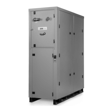
Johnson Controls
Johnson Controls RW Series Engineering guide
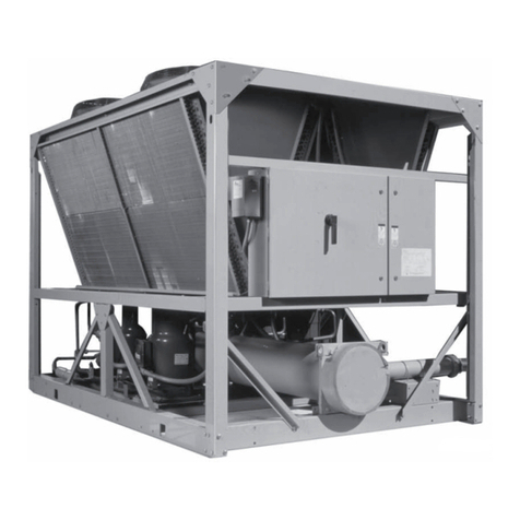
Johnson Controls
Johnson Controls York YCAL0014E Series Installation, operation & maintenance instructions
Hydac
Hydac RFCS Series Installation and maintenance manual
