MAXA HWA-A 06195-121031 Series Guide

AIR CONDITIONING
MANUALE UTENTE INSTALLATORE
USER INSTALLER MANUAL
A78
Serie/Series/Serie/Série Emissione/Issue
Ausgabe/Emission
HWA-A 06195÷121031
Catalogo/Catalogue/Katalog/Catalogue Sostituisce/Supersade
Ersetzt/Remplace
9-13
REFRIGERATORI D’ACQUA E
POMPE DI CALORE ARIA/ACQUA CON
VENTILATORI ASSIALI E COMPRESSORI
SCROLL DA 195 kW A 1031 kW.
AIRCOOLED LIQUID CHILLERS AND
HEAT PUMPS WITH AXIAL FANS
AND SCROLL COMPRESSORS
FROM 195 kW TO 1031 kW.
MUI01110E3205-01
-1

2
AIR CONDITIONING
0. ELENCO DOCUMENTI ALLEGATI
Elenco documentazione fornita a corredo della mac chi na
facente parte integrante del presente manuale.
- Quaderno tecnico
- Manuale microprocessore
- Certifi cato di garanzia
- Dichiarazione di conformità
- Schemi elettrici specifi ci
0. LIST OF ATTACHMENTS
List of documents supplied with the unit and forming an
integral part of this manual.
- Technical book
- Microprocessor manual
- Certifi cate of guarantee
- Declaration of conformity
- Specifi c electrical circuit

3
AIR CONDITIONING
INDICE CONTENTS
Argomento
ELENCO DOCUMENTI ALLEGATI
PREMESSA
Informazioni generali
Allegati
Avvertenze
DESCRIZIONE DELLA MACCHINA
Identifi cazione
Identifi cazione della macchina
Destinazione d'uso
Controindicazioni
Descrizione generale
SICUREZZA
Defi nizioni
Regole generali di sicurezza
Simbologia
Mappa dei segnali di sicurezza
Segnali di sicurezza
Dispositivi di emergenza e di sicurezza
Descrizione del rischio residuo
Rischio residuo in prossimità della macchina
Misure da adottare in caso di fuoriuscita di
gas frigorigeno
Operazioni con rimozione dei pannelli
ISPEZIONE, TRASPORTO
Ispezione
Stoccaggio
Sollevamento e trasporto
Disimballo
INSTALLAZIONE
Scelta del luogo di installazione
Collegamento idraulico
Generalità
Evaporatore
Subject
LIST OF ATTACHMENTS
INTRODUCTION
General information
Attachments
Warnings
UNIT DESCRIPTION
Identifi cation
Identifi cation
Intended use
Contraindications
General description
SAFETY
Defi nition
General safety regulations
Symbols
Location of safety signs
Safety signs
Emergency and safety devices
Description of residue risks
Residue risks near the unit
Measures to take in case of leaking refrige-
rant gas
Operations with the panels removed
INSPECTION AND TRANSPORT
Inspection
Storage
Lifting and transport
Unpacking
INSTALLATION
Choosing the installation site
Water connections
General
Evaporator
0
1
1.1
1.2
1.3
2
2.1
2.1.1
2.2
2.3
2.4
3
3.1
3.2
3.3
3.3.1
3.3.2
3.4
3.5
3.5.1
3.5.2
3.5.3
4
4.1
4.2
4.3
4.4
5
5.1
5.2
5.2.1
5.2.2
0
1
1.1
1.2
1.3
2
2.1
2.1.1
2.2
2.3
2.4
3
3.1
3.2
3.3
3.3.1
3.3.2
3.4
3.5
3.5.1
3.5.2
3.5.3
4
4.1
4.2
4.3
4.4
5
5.1
5.2
5.2.1
5.2.2

4
AIR CONDITIONING
Collegamenti elettrici
Generalità
Collegamento elettrico del fl ussostato/pres-
sostato differenziale
Collegamento elettrico della pompa di cir co la zio ne
Consensi esterni
AVVIAMENTO
Controlli pre li mi na ri all'avviamento
Messa in funzione
Verifi che durante il funzionamento
Generalità
Sbrinamento
(Solo unità pompa di calore)
Arresto del gruppo
FUNZIONAMENTO
Generalità
Fermata stagionale
RICERCA GUASTI
MANUTENZIONE E CONTROLLI PE RIO DI CI
Avvertenze
Generalità
Controlli mensili
Controlli quadrimestrali
Riparazioni del circuito frigo
Rabbocchi di refrigerante
DISMISSIONE E SMALTIMENTO
5.3
5.3.1
5.3.2
5.3.3
5.3.4
6
6.1
6.2
6.3
6.3.1
6.3.2
6.4
7
7.1
7.2
8
9
9.1
9.1.1
9.1.2
9.2
9.3
10
Electrical connections
General
Electrical connections to the fl ow switch/dif-
ferential water pressure switch
Electrical connections to the circulation pump
External signals
START UP
Preliminary controls
Start up
Checks during unit operation
General
Defrosting
(Only heat pump units)
Stopping the unit
OPERATION
General
Seasonal shut down
TROUBLE SHOOTING
ROUTINE MAINTENANCE AND CONTROLS
Warnings
General
Monthly controls
Four-monthly controls
Repairing the refrigerant circuit
Topping up the refrigerant liquid
SHUT DOWN AND DISPOSAL
5.3
5.3.1
5.3.2
5.3.3
5.3.4
6
6.1
6.2
6.3
6.3.1
6.3.2
6.4
7
7.1
7.2
8
9
9.1
9.1.1
9.1.2
9.2
9.3
10

5
AIR CONDITIONING
1. PREMESSA
1.1 INFORMAZIONI GENERALI
Questo manuale contiene le norme di installazione, uso
e manutenzione dei refrigeratori HWA-A, evidenziandone
ri schi e pericoli connessi. Esso è stato espressamente
studiato e sviluppato per permettere al personale pre po-
sto un utilizzo facile e in sicurezza dei refrigeratori d’ac qua
HWA-A. Leggere attentamente e completamente tutte
le in for ma zio ni in esso riportate. Prestare par ti co la re
at ten zio ne alle norme evidenziate con
in quanto se non osservate possono causare danno alle
persone, all’ambiente e/o alla macchina stessa.
La società declina ogni responsabilità per qual si a si uso
im pro prio della macchina, per mo di fi che alla stessa
non au to riz za te o per la non osservanza delle norme
riportate sul manuale.
Il manuale deve essere conservato il luogo sicuro e messo
a disposizione del personale addetto alla conduzione
ed alla manutenzione del refrigeratore.
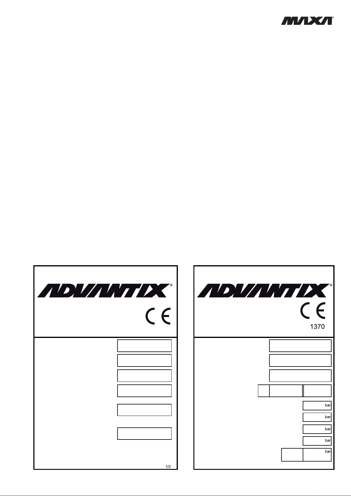
1.2 ALLEGATI
Fanno parte integrale del presente manuale i documenti
evidenziati a pag. 2.
1.3 AVVERTENZE
Le unità HWA-A sono state progettate e costruite per
ga ran ti re nel tempo grande affi dabilità di esercizio e
massima sicurezza; per questo e grazie alle scelte pro-
gettuali e realizzative, la società può ga ran ti re la totale
con for mi tà agli standard di sicurezza CE.
Ulteriore garanzia è assicurata dai collaudi cui la mac-
chi na è stata sottoposta in fabbrica.
All’utente resta quindi soltanto l’impegno di un uso
proprio e di una manutenzione preventiva conforme alle
in di ca zio ni contenute in questo manuale.
Ogni intervento, di qualsiasi natura, sulla
macchina deve essere preceduto da una
attenta lettura del presente manuale in tutte
le sue parti.
1. INTRODUCTION
1.1 GENERAL INFORMATION
This manual contains the installation, use and main te-
nance instructions for the HWA-A chillers, and highlights
all connected risks and perils. It has been expressly
pre pared and written to allow authorised users to use
the HWA-A water chillers in complete safety and with
the greatest of ease. Please read the whole of this
manual with care, paying special attention to the sec-
tions marked with
as non-compliance may cause harm to people, de te ri o rate
the environment and/or damage the unit.
The company declines all responsibility for any improper
use of the unit, unauthorised modifi cations or non-com-
pli ance with the instructions contained in this manual.
Please keep this manual in a safe place and make it
available to chiller operators and maintenance men.
1.2 ATTACHMENTS
The documents shown on page 2 form an integral part
of this manual.
1.3 WARNINGS
The HWA-A units have been designed and built to en-
sure long-term operating reliability and maximum safety;
for this reason and thanks to the company’s design and
con struc tion policy, the company is able to guar an tee that
this product totally complies with EC safety stand ards.
A further guarantee of this is provided by the factory
tests carried out on the unit.
The user, therefore, must only ensure the unit is properly
used and that maintenance operations are carried out
according to the indications contained in this manual.
The unit should not be touched until the whole of this
manual has been carefully read.

6
AIR CONDITIONING
Il manuale di installazione, uso e manuten-
zione deve essere sempre a disposizione
degliaddetti, i quali,prima di ogni operazione
sulla macchina, devono obbligatoriamente
leggerlo.
This installation, use and maintenance man u al must
always be kept within easy reach of authorised staff
who are obliged to read it before carrying out any
operations on the unit.

7
AIR CONDITIONING
2 DESCRIZIONE DELLA MACCHINA
Questo capitolo ha lo scopo di fornire una descrizione
generale delle caratteristiche principali della macchina
nel suo insieme, unitamente a quella dei principali com-
po nen ti, standard e opzionali.
2.1 IDENTIFICAZIONE
2.1.1 Identificazione della macchina
La macchina si identifi ca tramite le targhette poste sul
telaio e sul quadro elettrico. Le targhette riportano i
se guen ti dati:
- Ragione sociale dell'Azienda
- Indirizzo dell'Azienda
- Designazione della serie e del tipo di unità
- Numero di matricola
- Anno di costruzione
- Tipo e quantità di refrigerante
- Massima pressione ammissibile
- Taratura dei pressostati
- Simbolo della certifi cazione CE
- Caratteristiche elettriche
- Identifi cazione schema elettrico
2 UNIT DESCRIPTION
This chapter contains a general description of the main
unit characteristics, together with those of its principal
standard and optional components.
2.1 IDENTIFICATION
2.1.1 Unit identifi cation
The unit can be identifi ed throug the plats attached on
the frame and in the electrical box. This label con tains
the fol low ing in for ma tion:
- Manufacturer’s name
- Manufacturer’s address
- Description of the series and type of unit
- Series number
- Year of construction
- Type and quantity of refrigerant liquid
- Max. Allowable pressure
- Pressure switch set point
- EC certifi cation symbol
- Electrical characteristics
- Wiring diagram identifi cation
Modello Modello
Model Model
Matricola Matricola
Serial number Serial number
A
limentazione di Potenza
A
nno di costruzione
Main Power Construction yea
r
Corrente massima assorbita Refrigerant
e
Max absorbed current Refrigerant
ALT
A
HIGHT PRESSURE
BASS
A
LOW PRESSURE
ALT
A
HIGHT PRESSURE
BASS
A
LOW PRESSURE
Olio
2/2
Potere nominale di chiusura in cortocircuito
Rated short circuit making capacity
(PS) Max. Press. Ammissibile
kA
V/Hz/Ph
AGr.2 Kg
Oil
Schema elettrico n°
Wiring diagram Nr. Max. Allowable pressure (PS)
s

8
AIR CONDITIONING
2.2 DESTINAZIONE D’USO
I HWA-A sono refrigeratori con condensazione ad aria
de sti na ti a raffreddare acqua (eventualmente ad di zio na ta
con glicole etilenico inibito) che circola in un anello chiu-
so. Le unità a pompa di calore pos so no, a se con da del
ciclo di funzionamento scelto, raf fred da re o ri scal da re
l’acqua dell’anello.
Le unità a recupero di calore , possono, come sottopro-
dotto, riscaldare del l’ac qua che circola in un secondo
anello chiuso.
Il caldo, o il freddo, così prodotto può essere utilizzato
per impianti di climatizzazione o per processi industriali.
2.3 CONTROINDICAZIONI
Non impiegare in prossimità della macchina
prodotti infiammabili.
Non impiegare in prossimità della macchi-
na sostanze in grado di formare miscele
esplosive.
Non impiegare la macchina dove sussistono
problemi di impatto ambientale (vedi punto
3.5 pag. 13).
2.4 DESCRIZIONE GENERALE
Tutte le strutture sono realizzate in lamiera zincata con
ulteriore protezione ottenuta tramite verniciatura a pol ve ri
poliestere. La struttura è autoportante ed i pannelli sono
facilmente rimovibili in modo da permettere l’ac ces so
all’interno della unità per le operazioni di ma nu ten zio ne
e riparazione.
Gli schemi funzionali e la componentistica usata sono
allegati.
2.2 INTENDED USE
The HWA-A series of air condensation chillers have
been de signed to cool water (possibly containing inhib-
ited eth yl ene glycol) circulating in a closed circuit. The
heat pump units can cool or heat the water in the closed
circuit depending on which operating cycle is chosen.
The heat recovery units can also heat the water circulat-
ing in a second closed circuit.
The heat or cold produced can be used for air-con di tion ing
systems or industrial processes.
2.3 CONTRAINDICATIONS
Do not use infl ammable products near the unit.
Do not use substances that can form ex plo sive mix-
tures near the unit.
Do not use the unit in conditions that could be harm-
ful for the environment (see point 3.5 on page 13).
2.4 GENERAL DESCRIPTION
All the unit structures are made from galvanised sheet
metal and are further protected with polyester powder
paints. The structure is free standing and the panels are
easy to remove in order to allow access to the inside of
the unit for maintenance and repair operations.
The functional diagrams and the components used are
attached to this manual.

9
AIR CONDITIONING
3 SICUREZZA
3.1 DEFINIZIONI
In questo documento verranno utilizzate le seguenti
defi nizioni:
- Zone pericolose: qualsiasi zona all’interno e/o in
prossimità della macchina in cui la presenza di una
persona esposta costituisca un rischio per la sicurezza
e la salute di detta persona.
- Persona esposta: qualsiasi persona che si trovi inter-
namente o in parte in una zona pericolosa.
- Operatore/Manutentore: la o le persone incaricate di
far funzionare, regolare, eseguire la manutenzione,
riparare, movimentare la macchina.
3.2 REGOLE GENERALI DI SICUREZZA
È vietato alle persone non autorizzate avvi-
cinarsi alla macchina.
Prima di ogni intervento di manutenzione
sulla macchina, seguire scrupolosamente
quanto indicato nel capitolo 9 a pag. 30.
È vietato l’ingresso all’interno della macchi-
na. L’accesso è consentito solo al personale
qualificato e solo a macchina ferma.
È vietata la rimozione delle protezioni e
l’esclusione dei dispositivi di sicurezze e di
emergenza.
È vietato stazionare sulla macchina.
- Impiegare la macchina solo per l’uso a cui essa è
destinata.
- Il costruttore non risponde dei danni derivanti da un
impiego improprio della macchina o da modifi che
tecniche effettuate sulla macchina.
- Controllare regolarmente se i dispositivi di sicurezza
presentano un funzionamento corretto.
- Non smontare, modifi care o mettere fuori funzione
parti della macchina.
- Per tutti gli interventi da effettuare sulla macchina,
utilizzare esclusivamente attrezzi ed equipaggiamenti
idonei e in buone condizioni. Gli operatori dovranno
indossare i normali dispositivi di protezione individuali
(guanti, casco, occhiali, ecc.).
3 SAFETY
3.1 DEFINITION
This document uses the following defi nitions:
- Dangerous areas: any area inside and/or near to the
unit in which the presence of a person would give rise
to a risk for that person’s health.
- Exposed person: anyone who is wholly or partly inside
a dangerous area.
- Operator/Maintenance man: p e r s o n o r p e r s o n s a u t h o -
rised to operate, adjust, service, repair or move the
unit.
3.2 GENERAL SAFETY REGULATIONS
It is forbidden for unauthorised persons to approach
the unit.
Scrupulously observe the contents of Chapter 9
on page 30 before carrying out each maintenance
operation on the unit.
It is forbidden to enter the unit. Access is only permit-
ted to qualifi ed staff when the unit is disconnected.
It is forbidden to remove safety guards and by-pass
safety and emergency devices.
It is forbidden to stand on the unit.
- Only use the unit to do what it was built for.
- The manufacturer declines all responsibility for damage
deriving from improper use or technical modifi cations
made to the unit.
- Check the safety devices are in perfect working order
on a regular basis.
- Do not dismount, modify or disconnect unit parts.
- When working on the unit, only use suitable tools and
equipment in good condition. Operators must wear
normal personal protection equipment (gloves, helmet,
goggles, etc.).

10
AIR CONDITIONING
- I lavori sull’equipaggiamento elettrico devono essere
eseguiti solo da un elettricista qualifi cato.
- Gli interventi sul circuito frigorifero possono essere
effettuati solo da personale specializzato.
3.3 SIMBOLOGIA
Verifi care periodicamente lo stato delle targhette e prov-
vedere, in caso di necessità, al loro ripristino.
3.3.1 Mappa dei segnali di sicurezza
- Work on the electrical system of the unit may only be
carried out by a qualifi ed electrician.
- Work on the refrigerant circuit may only be carried out
by specialised staff.
3.3 SYMBOLS
Check the state of the plates on a regular basis and
repair them if necessary.
3.3.1 Location of safety signs
4
5
9 13 15
11 12
1
15
11 12 11
16
10
2
14
7
6
8
18
10
3
3

11
AIR CONDITIONING
ATTENZIONE
DISTANZA MINIMA TRA LA BATTERIA ED
OSTACOLI IN GENERE 1800 mm
ATTENTION
MINIMUM DISTANCE BETWEEN GRILL
AND OBSTACLES 1800 mm
VORSICHT
MINIMALE ENTFERNUNG ZWISCHEN
DER LAMELLENFLÄCHE ODER ANDEREN
HINDERNISSEN 1800 mm
ATTENTION
DISTANCE MINIMALE ENTRE LES
SURFACES AILETÉES ET ÉVENTUELS
OBSTACLES CES SOIVENT 1800 mm
ATTENZIONE
• DARE TENSIONE AI RISCALDATORI OLIO DEL CARTER ALMENO 12 ORE PRIMA
DELL’AVVIAMNETO DELL’UNITÀ NEGLI INTERVALLI DI FUNZIONAMENTO (AD ES.
PAUSA DEL FINE SETTIMANA) TOGLIERE L’ALIMENTAZIONE ELETTRICA.
• L’UNITÀ È MUNITA DI UN RITARDATORE ANTIRICIRCOLO E DI DISPOSITIVO PER
LA RIPARTENZA AUTOMATICA.
• PRIMA DI APRIRE IL SEZIONATORE FERMARE L’UNITÀ AGENDO SUGLI APPOSITI
INTERRUTTORI DI MARCIA O IN ASSENZA SUL COMANDO A DISTANZA.
• PRIMA DI ACCEDERE A PARTI INTERNE DELL’UNITÀ TOGLIERE TENSIONE
APRENDO IL SEZIONATORE GENERALE.
WARNING
• SUPPLY THE CRANKCASE HEATERS AT LEAST 12 HOURS BEFORE STARTING
THE UNIT DURING TEMPORARY STOP PERIODS (LIKE WEEK÷ENDSI NEVER
DISCONNECT ELECTRICAL SUPPLY TO THE UNIT.
• THE UNIT IS PROVIDED WITH DELAY RELAY AND WITH AUTOMATIC RESTART
DEVICE.
• BEFORE OPENING THE MAIN SWITCH, STOP THE UNIT BY ACTING ON THE
SUITABLE RUNNING SWITCHES OR THESE ARE IF NOT PRESENT, ON THE
REMOTE CONTROL.
• BEFORE SERVICING THE INNER COMPONENTS, DISCONNECT ELECTRICAL
SUPPLY BY OPENING THE MAIN SWITCH.
ACHTUNG
• DIE KURBELWANNENHEIZUNG MINDESTENS 12 STUNDEN VOR DER INBE-
TRIEBNAHME DES GERATS UNTER SPANNUNG SETZEN DIE KURBELWAN-
NENHEIZUNG WAHREND DER STILLSTANDSZEITEN DES GERATS NICHT
AUSSCHALTEN.
• DAS GERAT IST MIT SCHALTVERZOGERUNGSTIMER UND VORRICHTUNG FÜR
AUTOMATISCHEN WIEDERANLAUF AUSGESTATTET.
• VOR DEM OFFNEN DES HAUPTSCHALTERS SETZEN SIE DAS GERAT DURCH
BETATIGUNG DER ENTSPRECHENDEN BETRIEBSSCHALTER ODER WENN DIESE
NICHT VORHANDEN SIND, DURCH FERNBEDIENUNG AUSSER BETRIEB.
• BEVOR MAN DIE INTERNE GERATEKOMPONENTEN BERUHRT. MUSS DER
HAUPTSCHALTER GEOFFNET WERDEN.
NOTICE
• FOURNIR TENSION AUX RECHAUFFERS DU CARTER AU MOINS 12 HEURES
AVANT QUE L’UNITÉ SOIT DÉMARÉE NE COUPEZ PAS LA TENSION AUX
RÉCHAFFEURS PENDANTS DES COURTES PERIODES D’ARRET DE L’UNITE.
TELS QUE LE WEEK-END.
• L’UNITÉ EST EQUIPPÉE DE RELAIS ANTI COURT-CYCLE ET D’UN DISPOSITIF
POUR LE REDEMARRAGE AUTOMATIQUE.
• AVANT D’OUVRIR LE SÉCTIONNEUR GENERAL ARRETEZ L’UNITÉ EN AGISSANT
SUR LES INTERRUPTEURS DE MARCHE OU AU CAS OU IL N’YA PAS SUR LE
COMMENDE Á DISTANCE.
• AVANT DE TOUCHER LES COMPOSANT INTERNES A L’UNITÉ, COUPER LA
TENSION EN OUVRANT LE SECTIONNEUR GÉNÉRAL.
INGRESSO ACQUA REFRIGERATA
CHILLED WATER INLET
KALTWASSEREINTRITT
ENTRÉE EAU GLACÉE
USCITA ACQUA REFRIGERATA
CHILLED WATER OUTLET
KALTWASSERAUSTRITT
SORTIE EAU GLACÉE
SFIATO ARIA
AIR PURGE
ENTLÜFTUNGSVENTIL
PURGE AIR
R407C
POSIZIONE ANTIVIBRANTI
SHOCK ABSORBERS POSITION
SCHWINGUNGSDÄMPFERSPOSITION
POSITION ANTIVIBRANTS
PUNTI DI SOLLEVAMENTO
LIFTING POINTS
HEBENPUNKTEN
POINT DE SOULEVEMENT
- PRIMA DI RIEMPIRE L’IMPIANTO CHIUDERE
SFIATI E SPURGHI
- BEFORE CHARGING THE PLANT, CLOSE THE
DRAIN AND DE-AERATION VALVES
- BEVOR DIE ANLAGE GEFÜLLT WIRD, MÜSSEN
DIE ENHEERUNGS UND NTLÜFTUNGSVENTILE
ABGESPERT WERDEN
- AVANT REPLISSER L’ INSTALLATION FERMER
TOUS VIDANGES
- SUPERFICIE SCALDATA ELETTRICAMENTE
- ELECTRIC SURFACE HEATING
- ROHREN MIT ELECTRISCHEN HEIZUNG
- SURFACE CHAUFEE ELECTRIQUEMENT
ATTENZIONE
ATTENTION
VORSICHT
- PRESENZA DI ORGANI IN MOVIMENTO
- PRESENCE OF MOVING OBJECTS
- ANWESENHEIT VON GEGENSTÄNDEN
IN BEWEGUNG
- PRESENCE DES ORGANS EN MOUVEMENT
- PRESENZA DI FONTI DI CALORE
- PRESENCE OF HEAT SOURCES
- ANWESENHEIT VON WÄRMEQUELLEN
- PRESENCE DES SOURCES DE CHALEUR
-PRESENZA DI SUPERFICI CHE POSSONO
CAUSARE LESIONI
-PRESENCE OF SURFACES WHICH MIGTH CAUSE
LESIONS
- ANWESENHEIT VON FLÄCHEN, DIE VERLETZUNGEN
VERURSACHEN KÖNNEN
- PRESENCE DES SURFACES QUI PEUVENT LESER
max 63 mm
12
3
4
5
8
910
11
12
15
7
6
14
13
-INSTALLARE SEMPRE UN FILTRO ACQUA SUL CIRCUITO IDRAULICO
A PROTEZIONE DELL’ EVAPORATORE.
-PLEASE BUILT ALWAYS A WATER FILTER ON THE HYDRAULIC
CIRCUIT TO PROTECT THE EVAPORATOR.
-EIN WASSERFILTER AUF DEM HYDRALISCHEN KREIS ZUM SCHUTZ
DES VERDAMPFERS IMMER EINBAUEN.
-INSTALLER TOUJOURS UN FILTRE DE L’ EAU SUR LE CIRCUIT
HYDRAULIQUE A PROTECTION DE L’ EVAPORATEUR.
16
ATTENZIONE
ATTENTION
VORSICHT
!!
3.3.2 Segnali di sicurezza 3.3.2 Safety signs
R410A
R134a

12
AIR CONDITIONING
3.4
DISPOSITIVI DI EMERGENZA E DI SICUREZZA
Un dispositivo di emergenza che tolga ten-
sione dalla macchina deve essere previsto
all’esterno della stessa a cura di chi installa
la macchina.
3.5 DESCRIZIONE DEL RISCHIO RESIDUO
La descrizione del rischio residuo prende in con si de ra-
zio ne i seguenti elementi:
- a quale tipologia di pericoli è soggetto chi opera
nel l’am bi to della macchina;
- la descrizione dei principali pericoli;
- chi può essere esposto a tali pericoli;
- quali sono le principali misure di sicurezza adottate
per ridurre il rischio di infortuni.
Le indicazioni per la prevenzione degli infortuni di segui-
to riportate, con riferimento alle relative aree a rischio
re si duo, devono essere integrate con tutte le indica-
zioni generali del presente capitolo e con le norme di
pre ven zio ne infortuni vigenti nel paese di de sti na zio ne
dell’impianto.
3.5.1 Rischio residuo in prossimità della macchina
- Folgorazione, se non vengono effettuati cor ret ta men te
l’allacciamento elettrico e la messa a terra della mac-
chi na.
- Tagli o escoriazioni per la presenza di superfi ci ta glien ti.
- Aspirazione e successiva dispersione in ambiente
delle sostanze presenti sul luogo dell’installazione.
- Proiezione di eventuali oggetti che possano cadere
sulle pale dei ventilatori.
- Fuoriuscita di acqua (in caso di anomalia).
- Formazione di acqua di condensa e di ghiaccio nella
zona antistante la macchina durante il funzionamento
in riscaldamento delle macchine a pompa di calore.
- Alterazione del microclima (durante il fun zio na men to).
- Emissione di rumore (durante il funzionamento). I livelli
di pressione sonora delle singole unità sono riportati
sul quaderno tecnico
- Fuoriuscita di olii (per anomalia).
- Fuoriuscita del frigorigeno (per anomalia).
N.B. Il frigorigeno è una sostanza ad effetto serra. Si
tratta di vapori più pesanti dell’aria e che possono
provocare soffocamento riducendo l’os si ge no
disponibile per la respirazione. Una rapida eva-
po ra zio ne del liquido può causare con ge la men to.
3.4 EMERGENCY AND SAFETY DEVICES
An emergency external circuit breaker must be fi tted
by the unit installer to disconnect the unit from the
power supply.
3.5 DESCRIPTION OF RESIDUE RISKS
The description of residue risks includes the following
elements:
- the kind of danger the people working on the unit are
subjected to;
- description of the main dangers;
- who is exposed to such dangers;
- the main safety methods used to reduce the risk of
injury.
The following accident prevention instructions, with
ref er ence to the relative areas concerned by residue
risks, must be integrated with all the general indications
con tained in the present chapter and with the accident
prevention regulations in force in the country of in stal-
la tion.
3.5.1 Residue risks near the unit
- Electrocution if the unit is not properly corrected to the
mains power supply and earth circuit.
- Cuts or abrasions caused by sharp surfaces.
- Extraction and subsequent dispersion in the en vi ron-
ment of substances present in the installation site.
- Ejection of objects falling on the fan blades.
- Leaking water (in case of malfunction).
- Formation of condensation and ice in front of the unit
while the unit heat pumps are working.
- Alteration of the micro climate (during operation).
- Noise (during operation).The sound pressure levels
of each unit are carried in technical manual.
- Leaking oil (in case of malfunction).
- Leaking refrigerant liquid (in case of malfunction).
N.B. Refrigerant liquid is a substance which causes a
greenhouse effect. Its vapours are heavier than
air and can cause suffocation by reducing the
amount of oxygen available for breath ing. Rapid
evaporation of the liquid can cause freezing to
occur.

13
AIR CONDITIONING
3.5.2 Misure da adottare in caso di fuoriuscita di
gas frigorigeno
- Tipo di prodotto:
R407C - R410A - R134a
- Misure di pronto soccorso:
Informazione generale:
non somministrare alcunchè a persone svenute.
Inalazione:
portare all’aria aperta. Ricorrere all’ossigeno o alla
respirazione artifi ciale se necessario. Non som mi-
ni stra re adrenalina o sostanze similari.
Contatto con gli occhi:
sciacquare accuratamente ed abbondantemente
con acqua per almeno 15 minuti e rivolgersi ad un
medico.
Contatto con la pelle:
Lavare subito abbondantemente con acqua. To glier si
immediatamente tutti gli indumenti con ta mi na ti.
- Misure in caso di fuoriuscita accidentale:
Precauzioni individuali:
evacuare il personale in aree di sicurezza. Pre ve de re
una ventilazione adeguata. Usare mezzi di pro te zio ne
personali.
Precauzioni ambientali:
intercettare l'emissione.
Metodi di pulizia:
impiegare prodotti assorbenti.
3.5.3 Operazioni con rimozione dei pannelli
Alcune delle operazioni e/o verifi che di seguito descritte
richiedono la rimozione dei pannelli del refrigeratore per
accedere all’interno dello stesso.
Prima di rimuovere qualsiasi pannello pe-
rimetrale, eccezion fatta per quello che
protegge il quadro elettrico (facilmente
riconoscibile dalle griglie di presa d’aria), è
obbligatorio togliere tensione.
Si fa presente che all’interno dell’unità, anche a mac-
chi na ferma possono esserci superfi ci calde (tubazioni,
com pres so re, ecc.), o fredde (compressore, separatore
d’aspi ra zio ne, ecc.), taglienti (alette batterie) o corpi in
mo vi men to (ventilatori).
Pertanto tali operazioni devono essere ef-
fettuate solo da personale qualificato che
indossi indumenti di sicurezza.
3.5.2 Measures to take in case of leaking
refrigerant gas
- Product type:
R407C - R410A - R134a
- First aid measures:
General information:
Do not give anything to people who have fainted.
Inhalation:
take the person out into the open air. Use oxygen
or artifi cial respiration if necessary. Do not give
adren a line or similar substances.
Contact with eyes:
carefully rinse with abundant water for at least 15
minutes and see a doctor.
Contact with the skin:
Wash with abundant water and remove all con tam i-
nat ed clothing immediately.
- Measures to take in case of accidental leaking:
Personal precautions:
evacuate all staff to safety areas. Make sure the
area is suitably ventilated. Use personal protection
equip ment.
Environmental precautions:
to intercept the emission.
Cleaning methods:
to employ absorbent products.
3.5.3 Operations with the panels removed
Some of the following operations and/or controls require
the panels of the unit to be removed in order to access
the inside of the unit.
Before removing an outer panel, except for the one
protecting the electrical panel (easy to recognise due
to its ventilation slits), the unit must be disconnected
from the mains power supply.
Please note that some surfaces inside the unit may be
hot (piping, compressor, etc.), cold (compressor, suction
separator, etc.), sharp (coil fi ns) or moving (fans) even
when the unit is not working.
These operations may only be carried out by qualifi ed
staff wearing safety clothing.

14
AIR CONDITIONING
Verifi che di funzionamento possono richiedere il fun zio-
na men to (totale o parziale dell’unità) con un pannello
aperto. In tal caso il pannello va rimosso a macchina
ferma.
Queste verifiche sono particolarmente peri-
colosee sono pertanto riservate apersonale
altamente qualificato.
Operare come segue:
- Togliere tensione tramite l’interruttore generale.
- Aprire il quadro elettrico e disattivare, togliendo i
relativi fusibili, gli organi di cui non è necessario il
fun zio na men to per la verifi ca che si deve effettuare.
- Richiudere il quadro elettrico.
- Rimuovere il pannello interessato.
- Avviare l’unità.
- Effettuare le verifi che richieste con la massima cau te la
e con l’utilizzo di protezioni individuali.
- Completate le verifi che, arrestare l’unità e rimettere
al suo posto il pannello precedentemente tolto.
- Togliere tensione e rimettere al loro posto gli eventuali
fusibili precedentemente tolti.
- Richiudere il quadro elettrico.
4. ISPEZIONE, TRASPORTO
4.1 ISPEZIONE
All’atto del ricevimento dell’unità, verifi carne l’integrità.
Poiché la macchina è stata accuratamente controllata
prima di lasciare la fabbrica, eventuali danni sono da
imputare al trasportatore. Si raccomanda perciò di an-
no tar li sul Foglio di Consegna prima di controfi rmarlo.
Avvisare tempestivamente la società o l’Agen te sul l’en ti tà
del danno riportato dall’unità.
Il Cliente deve sempre compilare un rapporto scritto che
riguarda ogni eventuale danno subito dalla macchina.
4.2 STOCCAGGIO
La temperatura dell’ambiente in cui vengono im ma gaz-
zi na te le unità deve essere compresa tra -20 e +50°C.
Operating checks may require the unit to work (totally
or partially) while a panel is open. In this case the panel
should be removed when the unit is not working.
These checks are particularly dangerous and may
only be carried out by highly qual i fi ed staff.
Proceed as follows:
- Turn off mains power with the main power switch.
- Open the electrical panel and remove the relative fuses
to disconnect the components that do not need to be
working in order to carry out the relative check.
- Close the electrical panel.
- Remove the panel in question.
- Start the unit.
- Carry out the relative check with the greatest of care
and using personal protection equipment.
- After completing the check, stop the unit and put the
panel back in place.
- Turn off mains power and put back any fuses that were
previously removed.
- Close the electrical panel.
4. INSPECTION AND TRANSPORT
4.1 INSPECTION
Check the condition of the unit on receipt. As the unit was
carefully checked before leaving the factory, any claims
for damages should be addressed to the forwarder. Any
damage should therefore be indicated on the Delivery
Note before signing it.
Please inform the company or the Agent of the nature
of the damage to the unit immediately.
The Customer must always write a report describing any
damage caused to the unit.
4.2 STORAGE
The temperature in the area where the units are stored
must range between -20 and +50°C.
4.3 LIFTING AND TRANSPORT

15
AIR CONDITIONING
4.3 SOLLEVAMENTO E TRASPORTO
Durante lo scarico ed il posizionamento dell’unità, pre-
sta re molta attenzione alle manovre che non devono in
alcun modo essere brusche e/o violente. Non utilizzare
come punti di sollevamento le tubature o altri com po-
nen ti della macchina.
La macchina va movimentata esclusivamente come
in di ca to sulla targhetta posta sulla macchina stessa.
I punti di sollevamento sono chiaramente evidenziati
con l’etichetta .
Attenzione!
Intutte le operazioni di sollevamento assicu-
rarsi di aver ancorato saldamente l’unità per
evitare ribaltamenti o cadute accidentali.
4.4 DISIMBALLO
L’imballo va tolto solo quando l’unità è giunta sul posto
di installazione e non dovrà più essere movimentata.
Rimuovere con cura l’imballo della macchina, evitando
di danneggiare la stessa.
Poiché i materiali che costituiscono l’imballo sono di
natura diversa (legno, polietilene(PE), polistirolo, carto-
ne, ecc.), si consiglia di conservarli separatamente e di
con se gnar li alle ditte specializzate nello smaltimento e
nel riciclaggio degli stessi allo scopo di salvaguardare
l’am bien te.
When unloading and positioning the unit, take great care
not to make sudden and/or violent manoeuvres. Do not
lift the unit by its piping or any other components.
The unit should only be moved as shown in the plate
attached to it.
The lifting points are clearly indicated with the label.
Attention!
Make sure the unit is securely anchored before lifting
it in order to prevent it from accidentally overturning
or falling.
4.4 UNPACKING
Only unpack the unit when it has reached the installation
site and no longer needs to be moved.
Remove the packing material with care, making sure
not to damage the unit.
Given that various kinds of packing materials are used
(wood, polyethylene(PE), polystyrene, cardboard, etc.),
they should be separated and delivered to specialised
disposal and recycling companies for environmental
reasons.
per unità con lunghezza 6700 [mm] für Gerät mit Länge 6700 [mm]
max 63 mm
max 63 mm
- PUNTI DI SOLLEVAMENTO
- LIFTING POINTS
- HEBEPUNKT
- POINT DE SOULÈVEMENT
-
PUNTOS DE LEVANTAMIENTO
- PONTOS DE ELEVAÇÃO
040.02.0
- PUNTI DI SOLLEVAMENTO
- LIFTING POINTS
- HEBEPUNKT
- POINT DE SOULÈVEMENT
-
PUNTOS DE LEVANTAMIENTO
- PONTOS DE ELEVAÇÃO
040.02.0

16
AIR CONDITIONING
5 INSTALLAZIONE
5.1 SCELTA DEL LUOGO DI INSTALLAZIONE
Nella scelta del luogo di installazione si dovrà tenere
conto di:
- Peso dell’unità:
Lasoletta di appoggio dell’unità deve essere
perfettamenteorizzontale ed ingrado di sop-
portare il peso in funzionamento dell’unità.
È opportuno costruire una soletta di supporto di di men-
sio ni proporzionate all’unità. Ciò si rende in particolar
modo necessario quando l’unità deve es se re posta
su terreno instabile (giardini, terreni di riporto, ecc.).
La soletta deve:
• appoggiare su opportune fondamenta, avere un’al tez za,
rispetto al terreno circostante, di circa 10-15 cm;
• essere orizzontale ed in grado di sopportare circa
il 200% del peso di esercizio della macchina. Si
con si glia di interporre una guarnizione di sughero
ade gua ta men te sigillata lungo il perimetro.
- Spazi:
Ènecessarioverificareche glispazidirispetto
riportatisul quadernotecnico dell’unitàsiano
lasciati liberi.
Ridurre lo spazio richiesto può signifi care diffi coltà o
impossibilità di effettuare le operazioni di ma nu ten zio ne
e/o malfunzionamento dell’unità a causa di ri du zio ne
della portata d’aria che investe la batteria con den san te
o di ricircolo della stessa.
Si fa presente che non sono ammessi osta-
coli quali tettucci, pensiline o coperture in
genere al di sopra della macchina.
Si tenga presente che le unità a pompa di calore
danno luogo a formazione di ghiaccio e condensa
che si riversa sul pavimento antistante l’unità. Si dovrà
per tan to prov ve de re a raccogliere e drenare l’acqua di
condensa e sbrinamento per evitare che il pavimento
diventi sdruc cio le vo le.
Tutta la zona di rispetto dovrà essere in-
terdetta, fatta eccezione per gli operatori e
manutentori addetti alla macchina.
- Rumore:
Durante il suo funzionamento, l’unità genera del
ru mo re, evitare pertanto l’installazione in ambienti
ri ver be ran ti.
L’unità dovrà essere posizionata con il lato batteria
rivolto nella direzione in cui la rumorosità è meno critica.
- Venti predominanti:
Il vento può alterare le condizioni di funzionamento,
per minimizzarne gli effetti si consiglia di posizionare
l’unità con il lato lungo parallelo alla direzione dei venti
pre do mi nan ti.
- Vibrazioni:
Benché le macchine trasmettano al terreno un basso
livello di vibrazioni, è in ogni caso consigliabile frapporre
fra il basamento delle stesse ed il piano di appoggio
un nastro di gomma rigido.
Quando si rende necessario un isolamento maggiore è
opportuno l’utilizzo di supporti antivibranti (in gom ma
o a molla)
5 INSTALLATION
5.1 CHOOSING THE INSTALLATION SITE
When choosing the installation site the following points
should be considered:
- The weight of the unit:
The supporting surface under the unit must be per-
fectly horizontal and able to withstand its operating
weight.
A supporting surface with an appropriate area should be
built. This is particularly important if the unit is installed
on unstable ground (gardens, embankments, etc.).
The supporting surface must:
• lie on suitable foundations and be about 10-15 cm
higher than the surrounding ground;
• be horizontal and able to withstand about 200% of
the weight of the unit in operation. A suitable sealed
layer of cork should be placed along the perimeter.
- Spaces:
Make sure that suffi cient free space, as in di cat ed on
the technical book, is left around the unit.
Less space will make it diffi cult or impossible to carry
out maintenance operations and/or lead to faults in
the unit due to the reduction in the air fl ow on the
condenser coil or its recirculation.
Please note that obstacles such as can o pies, shelters
or coverings in general are not permitted.
Please note that the heat pump units cause ice and
condensation to form and drain onto the fl oor in front
of the unit. This water must therefore be collected and
drained to prevent the fl oor from becoming slippery.
People may not enter the unit area unless they are
authorised operators and main te nance personnel.
-
Noise:
The unit generates noise while it’s working; do not
install it in reverberating rooms. The unit must be po-
sitioned with the coil side facing the direction where
noise is less critical.
- Prevailing winds:
Wind may alter operating conditions; to minimise its
effects the unit should be positioned with the long side
parallel to the direction of prevailing winds.
- Vibrations:
Although the units transmit a low level of vibrations
to the ground, a sheet of rigid rubber should always
be placed between the unit base and the supporting
surface.
If greater insulation is required, vibration moisting
sup ports should be used (in rubber or with springs).

17
AIR CONDITIONING
5.2 COLLEGAMENTO IDRAULICO
5.2.1 Generalità
Per la realizzazione del circuito idraulico dell’acqua
re fri ge ra ta è buona norma seguire attentamente le in-
dicazioni sotto riportate oltre che la normativa vigente.
Attenzione!
Le tubazioni idrauliche devono essere op-
portunamente staffate per non gravare con
il loro peso sul refrigeratore.
- Raccordare le tubazioni al refrigeratore tramite giunti
fl essibili al fi ne di evitare la trasmissione delle vi bra zio ni
e compensare le dilatazioni termiche.
- Installare sulle tubazioni i seguenti componenti:
• valvole di intercettazione (saracinesche) per isolare
l’unità dal circuito idraulico;
• indicatori di temperatura e pressione per la normale
manutenzione e controllo del gruppo;
• pozzetti sulle tubazioni d’ingresso ed uscita per i
rilievi di temperatura, qualora non fossero presenti
indicatori di temperatura;
• fi ltro metallico (tubazione in ingresso) a rete con
maglia non superiore ad 1mm, per proteggere lo
scambiatore da scorie o impurità presenti nelle
tu ba zio ni;
• valvole di sfi ato, da collocare nelle parti più elevate
del circuito idraulico, per permettere lo sfogo del l’aria;
• vaso di espansione, (se non già presente)
dimensionato in funzione della quantità
d’acqua contenuta nell’impianto e delle
escursioni termiche prevedibili, e valvole
di carico automatica per il mantenimento
della pressione del sistema e compensare
le dilatazioni termiche del fluido.
• rubinetto di scarico e, ove necessario, serbatoio di
drenaggio per permettere lo svuotamento del l’im-
pian to per le operazioni di manutenzione o le pause
stagionali.
Attenzione!
È indispensabile installare un flussostato di
sicurezza (se non già presente il flussostato/
pressostato differenziale) su un tratto retti-
lineodi tubazionead una distanza dall’uscita
dello scambiatore pari a non meno di 8-10
volte il diametro della tubazione stessa. In
caso contrario la garanzia viene a decadere
immediatamente.
5.2 WATER CONNECTIONS
5.2.1 General
Please carefully carry out the following instructions and
observe current law when installing the chilled water
circuit.
Attention!
The water pipes must be suitably supported
with brackets in order not to weigh on the
chiller.
- Connect the pipes to the chiller with fl exible joints in
order to prevent the transmission of vibrations and to
compensate thermal expansion.
- Install the following components on the pipes:
• shut-off valve (moisters) for shutting off the water
mains;
• temperature and pressure gauges for routine main-
te nance and inspection purposes;
• check points on the inlet and outlet pipes for meas-
ur ing temperatures if temperature indicators are not
fi tted;
• metal fi lter (inlet pipe) with a maximum mesh ap er-
ture of 1 mm to protect the exchanger from waste
or impurities in the pipes;
• relief valves, fi tted in the uppermost parts of the
water circuit, for expelling air;
• expansion tank (if not already fitted) of a
suitable size for the quantity of water con-
tained in the system and the expected tem-
perature range, and an automatic inlet valve
for maintaining the pressure of the system
and compensating the thermal expansion
of the fluid.
• drain valve or, where necessary, drain tank for
emp ty ing the circuit for maintenance operations or
sea son al shut downs.
Attention!
A safety flow switch has to be installed (if
the flow switch/differential water pressure
switch are not already fitted) along a straight
section of piping at a distance from the ex-
changer outlet of not less than 8-10 times
the diameter of the piping. The guarantee
will immediately become null and void if the
above is not complied with.

18
AIR CONDITIONING
5.2.2 Evaporatore
Èdiimportanzafondamentalechel’ingressodell’ac-
qua avvenga in corrispondenza della connessione
contrassegnataconlatarghetta“ENTRATAACQUA”.
Per gli attacchi idraulici vengono utilizzate connessioni fi lettate
maschio o fl angiate, a seconda dei modelli (fare riferimento ai
disegni dimensionali, così come per la posizione degli attacchi).
È di fondamentale importanza realizzare il circu-
ito idraulico in modo tale che venga garantita la
costanza della portata d’acqua allo scambiatore
inqualsiasicondizionedi funzionamento. Unapor-
tata d’acqua non costante può essere accettata
solo nelle unità con desurriscaldatori.
Poiché la richiesta frigorifera dell’utenza non coincide
generalmente con quella erogata dai compressori, l’a-
zio ne degli stessi è molto spesso intermittente. Negli
im pian ti a basso contenuto d’acqua, dove l’effetto di
inerzia termica della stessa è meno sensibile, è op por-
tu no verifi care che il contenuto dell’impianto soddisfi la
se guen te relazione: V > P/115n
dove:
V = volume d’acqua (litri)
P = potenza resa dall’unità (Watt)
n = numero di gradini di parzializzazione.
Se non vengono raggiunti i volumi sopraccitati, è ne ces sa rio
prevedere un serbatoio d’accumulo tale che, som ma to alla
capacità dell’impianto, venga raggiunto il valore fornito dalla
relazione riportata. Tale serbatoio non richiede particolari
accorgimenti, salvo che, allo stesso modo delle tubature
dell’acqua re fri ge ra ta, va isolato al fi ne di non penalizzare la
resa dell’impianto e di evitare fenomeni di condensazione.
È buona norma installare una valvola di sicurezza
sul circuito idraulico (se non già presente). In caso
dianomaliegravinell’impianto(ades.incendio)essa
permetterà di scaricare il sistema evitando possibili
scoppi.Collegaresemprelo scarico adunatubazio-
ne di diametro non inferiore a quello dell’apertura
dellavalvola,econvogliarloinzonenellequaliilgetto
non possa recare danno alle persone.
Attenzione!
Durantele operazioni diallacciamento idrau-
lico non operare mai con fiamme libere in
prossimità o all’interno dell’unità.
5.3 COLLEGAMENTI ELETTRICI
5.3.1 Generalità
Queste operazioni devono essere effettuate
solo da personale specializzato.
Prima di effettuare qualsiasi operazione su
parti elettriche assicurarsi che non vi sia
tensione.
5.2.2 Evaporator
It is vitally important that the water enters the unit
from the connection point marked with the “WATER
INLET” plate.
Threaded or fl anged male unions, depending on the models,
are used to make water connections (please refer to the
scale drawings which also show the position of the unions).
It is vitally important to connect the water circuit so that
the fl ow of water to the ex chang er is always constant
under all op er at ing conditions. A variable fl ow of water
is only accepted for units with the desuperheaters.
As the demand for cooling by utilities does not gener-
ally coincide with what is delivered by the compressors,
they often work intermittently. In units with a low water
content, where the effect of thermal inertia is not felt so
much, the system should be checked to make sure it
satisfi es the following relation:
V > P/115n
where:
V = volume of water (litres)
P = power capacity of the unit (Watts)
n = number of capacity steps.
If the above volumes are not obtained, a storage tank
should be installed so as to satisfy the above relation
when added to the capacity of the system.
This tank requires no special features; it just needs to
be isolated, just like the chilled water pipes, so as not
to affect the performance of the system and to prevent
the formation of condensation.
A safety valve should be installed on the water circuit (if
not already fi tted). In case of serious system faults (e.g.
fi re) this will allow the system to be drained in order to
prevent the risk of ex plo sions. Always connect the drain
to a pipe with a diameter not less than that of the valve
opening and install the outlet in an area where the jet
cannot cause harm to people.
Attention!
While connecting the water circuit, never work with
naked fl ames near to or inside the unit.
5.3 ELECTRICAL CONNECTIONS
5.3.1 General
These operations may only be carried out by spe-
cialised staff.
Before carrying out any operations on elec tri cal
components, make sure the unit is disconnected
from the mains power supply.
Make sure that the mains power supply corresponds to the rated
values of the unit shown on the plate (voltage, number of phases,
frequency). The unit must be con nect ed with a three-pole cable

19
AIR CONDITIONING
Verifi care che l’energia disponibile corrisponda ai dati nomi-
nali dell’unità riportati sulla targhetta (tensione, nu me ro di fasi,
frequenza). L’allacciamento avviene tra mi te cavo tripolare più
terra. I collegamenti elettrici devono essere effettuati se guen do
attentamente le istruzioni riportate sullo schema elettrico allegato
all’unità. Il collegamento a terra è obbligatorio per legge. Si deve
perciò provvedere al collegamento del cavo di terra con la barra
di terra situata nel quadro elettrico e con tras se gna ta con PE.
L’alimentazione del circuito ausiliario è derivata dalla linea di
potenza tramite un trasformatore situato nel quadro elettrico.
La sezione del cavo e le protezioni di linea
devono essere conformi a quanto indicato
nelloschemaelettrico e nell’appositascheda
allegata all’unità.
Rispettare la sequenza delle fasi, viceversa la macchina
non potrà funzionare. La tensione di alimentazione non
deve subire variazioni superiori a ±5% e lo squilibrio tra
le fasi deve essere sempre inferiore al 2%.
Il funzionamento deve avvenire entro i valori
sopra citati, pena la decadenza immediata
della garanzia.
5.3.2 Collegamento elettrico del flussostato/pres-
sostato differenziale
Il refrigeratore deve funzionare solo in presenza di fl usso
d’acqua. Il fl ussostato/pressostato differenziale (se non già
presente)deve quindi essere col le ga to come ri por ta to sullo
schema elettrico che è a corredo della macchina stessa.
5.3.3
Collegamento elettrico della pompa di circolazione
La pompa di circolazione(se non già istallata) deve
sempre essere collegata al controllo dell’unità come
previsto dallo schema elet tri co.
La pompa deve essere avviata prima della
partenza del refrigeratore e fermata dopo
l’arresto di quest’ultimo (ritardo minimo
consigliato: 60 secondi).
5.3.4 Consensi esterni
Qualora si desideri effettuare un ON-OFF remoto del l’u-
ni tà è necessario collegare il consenso esterno ai contatti
indicati sullo schema elettrico.
Per il collegamento elettrico al contatto ON-OFF remoto
e funzionamento CHILLER-POMPA DI CALORE remoto,
non installare i cavi di comando all’interno delle canaline
usate per i cavi di potenza; nel caso non fosse possibile,
utilizzare un cavo schermato.
Quandosi effettuanoi collegamenti descritti
ai paragrafi 5.3.2 - 5.3.3 - 5.3.4 attenersi
scrupolosamente a quanto riportato nello
schema elettrico. I cavi di collegamento
devono avere sezione minima di 1,5 mm².
plus earth. Electrical connections must be made carefully following
the instructions shown on the wiring diagram attached to the unit.
The earth connection is obligatory by law. The earth cable must
be connected to the earth bar located in the electrical panel and
marked with PE. Auxiliary circuit power is supplied by the power
line by means of a transformer located in the electrical panel.
The cross-section of the cable and the line protections
must comply with the in di ca tions shown on the wiring
diagram and in the relative sheet attached to the unit.
Observe the phase sequence, otherwise the unit will
not work.
Input voltage must not exceed variations of over ±5%
and phase unbalance must always be less than 2%.
Unit operation must always take place with in the
above values as otherwise the guar an tee will im-
mediately become null and void.
5.3.2 Electrical connections to the fl ow switch/water dif-
ferential pressure switch
The chiller (if not already fi tted) must only work while
water is fl owing. The fl ow switch/differential water pres-
sure switch must there fore be con nect ed as shown on
the wiring diagram sup plied with the unit.
5.3.3
Electrical connections to the circulation pump
The circulation pump must always be connected to the
unit control system as shown on the wiring diagram.
The pump must be started up before starting up the
chiller while it must be stopped after the chiller has
stopped (minimum rec om mend ed delay: 60 seconds).
5.3.4 External signals
If a remote ON-OFF command is required, connect the
external enable to the contacts shown on the wiring
diagram.
For the electrical connection to the remote On-off con tact
and remote Chiller heat pump operation, do not install
drive cables inside the ducts used for power cables; if it
is not possible, a shielded cable must be used.
When making the connections described in para-
graphs 5.3.2 - 5.3.3 - 5.3.4, carefully fol low the
indications shown in the wiring di a gram. The con-
necting cables must have a minimum cross-section
of 1.5 mm².

20
AIR CONDITIONING
6 AVVIAMENTO
6.1
CONTROLLI PRELIMINARI ALL’AVVIAMENTO
- Verifi care che i collegamenti elettrici siano stati ese gui ti
correttamente e che siano stati serrati tutti i morsetti.
- Verifi care il serraggio a fondo dei tappi portafusibile
- Verifi care che la tensione sui morsetti L1, L2, L3, sia quella
riportata sulla targa dell’unità (tolleranza am mes sa) ±5%
controllabile con un tester. Se av ven go no frequenti
variazioni di tensione, si prega di con tat ta re il nostro
uffi cio tecnico per la scelta di opportune pro te zio ni.
- Verifi care che i manometri (quando presenti) indichino
una ade gua ta pressione. I manometri possono essere
muniti di ru bi net ti di intercettazione. Essi vanno aperti
solo quan do ne ces sa rio, una volta effettuati i rilievi
devono essere chiusi nuovamente
- Controllare, eventualmente tramite l’ausilio di un cer-
ca fu ghe, che non vi siano perdite di fl uido refrigerante.
- Verifi care che le resistenze del carter (se presenti)
siano correttamente alimentate.
L’inserimento delle resistenze deve essere
fatto almeno 12 ore prima dell’avviamento,
ed avviene automaticamente alla chiusura
del sezionatore generale (posizione I).
Per controllare se le resistenze funzionano cor ret ta men te,
verifi care che la parte inferiore del com pres so re sia ad
una temperatura di 10÷15°C superiore a quella ambiente.
- Verifi care il corretto collegamento del circuito idrau li co
(de vo no essere rispettate le indicazioni sulle targhette
a bordo macchina).
- Assicurarsi che il circuito idraulico sia stato pre ven ti -
va men te pulito: si consiglia di effettuare un lavaggio del
circuito idraulico by passando l’unità e quindi ve ri fi ca re
lo stato di pulizia del fi ltro dell’impianto.
- Le macchine vengono spedite con sfi ati e drenaggi
aperti. Apposite targhette indicano le loro posizioni.
Essi vanno chiusi all’atto dell’installazione quando si
riempie il circuito idraulico.
-
Nei modelli provvisti di gruppo idronico, il tappo di scarico
acqua della pompa è stato tolto, al fi ne di scaricare l'acqua
in essa contenuta ed evitare problemi di gelo durante la
stagione invernale. Il tappo è stato collocato all'interno
della busta contenente la documentazione dell'unità.
- Verifi care che l’impianto idraulico sia stato sfi atato, eli-
mi nan do ogni eventuale residuo d’aria, l’operazione va
ese gui ta caricando gradualmente e aprendo i di spo si ti vi
di sfi ato disposti dall’installatore nella parte su pe rio re
del l’im pian to (a tale proposito consultare la se zio ne 5.2).
- Qualora si utilizzi acqua glicolata si può spostare il
set point antigelo, il valore deve essere pari al valore
della temperatura di congelamento del fl uido più 6K.»
- Prima di avviare la pompa è necessario controllare che le
parti in movimento ruotino liberamente. A tale scopo togliere il
copriventola (3) dalla sede del coperchio posteriore del motore
(1) ed agire con un cacciavite sull’intaglio previsto sull’albero
motore dal lato ven ti la zio ne. In caso di bloccaggio ruotare il
cacciavite bat ten do leggermente su di esso con un martello
(fi g. A), rimontare il copriventola.
6 START UP
6.1 PRELIMINARY CONTROLS
- Make sure that the electrical connections have been
made correctly and that all the terminals have been
well tightened.
- Verify the deep closing of the fuses-holder cover
- Use a tester to make sure that the voltage on terminals
L1, L2, L3, is equal to that shown on the rating plate (per-
mitted tolerance ±5%). If voltage is subject to frequent
variations, please contact our technical offi ce in order
to decide on suitable protection devices.
- Make sure that the pressure gauges (when fi tted) show
the correct pressure. The pressure gauges can be fi t-
ted with shut-off valves. These must only be opened
when necessary and closed again after inspection.
- Use a leak tester, if necessary to make sure there are
no leaks of refrigerant liquid.
- Check that the heating elements of the sump (if fi tted)
are correctly powered.
The heating elements must be turned on at least 12
hours before start up; this takes place automatically
when the main power switch is closed (position I).
To check if the heating elements work correctly, make
sure that the lower part of the compressor is 10÷15°C
higher than room temperature.
- Check the water circuit is correctly connected (the
indications on the unit rating plate must be observed).
- Make sure that the water circuit has been cleaned
beforehand: the water circuit should be washed, by-
pass ing the unit, and then the system fi lter checked
for dirt.
- The units are despatched with the relief valves and
drains open. Special plates show where they are lo-
cat ed. They must be closed during installation before
the water circuit is fi lled.
- In the models with built-in hydraulic kit, the pump water
drain plug has been removed for discarge of the water
therein and to prevent freezing during winter season.
The plug is included into the envelope containing the
documentation of the unit.
- Make sure the water circuit has been well vented to
eliminate any air residues; this operation is carried
out by gradually loading and opening the relief valves
fi tted to the uppermost part of the unit by the installer
(please consult section 5.2 for further information).
- In case water with glycol is used, the anti-freezing set
point can be moved, the value must be equal to the value
of the freezing temperature of the fl uid plus 6K.»
- Before starting the pump, make sure that the moving
parts turn freely. To do so, remove the fan cover (3)
from the rear motor cover (1), insert a screwdriver into
the notch on the ventilation side of the motor shaft and
rotate it. If it blocks, rotate the screwdriver by gently
hitting it with a hammer (fi g. A). Then put the fan cover
back.
This manual suits for next models
1
Table of contents
Other MAXA Chiller manuals

MAXA
MAXA i-32V5C MIDI 0121 User manual

MAXA
MAXA A68 User manual

MAXA
MAXA HWA1-A 0140 User manual

MAXA
MAXA i-32V5H MIDI 0121 Service manual

MAXA
MAXA i-32V504 User manual

MAXA
MAXA HWA-ZA User manual

MAXA
MAXA HMV-A Series User manual

MAXA
MAXA i-32V504 User manual

MAXA
MAXA i-32V5C MIDI 0121 User manual

MAXA
MAXA C12 User manual