Tecumseh Silensys B08Z User manual

Silensys
Installation instruction

2/12
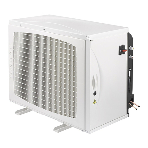
These instructions concern SILENSYS® units as described in chapter 2.
Read carefully the following instructions before installing the unit.
1ADVICE
TRANSPORT
For information regarding the supply of these units refer to “general terms and conditions”.
INSTALLATION
-This unit and relating equipment must be installed by qualified staff.
-The installation of the unit, including refrigeration and electrical connection, is subject to
the norms and technical standards in the respective country.
-TECUMSEH EUROPE S.A. declines all responsibility if installation and maintenance are not
carried out in accordance with these instructions.
2TECHNICAL DATA
1.1. Name plate
REFERENCE DESCRIPTION
AVoltage
BFrequency
CNumber of phases
DNominal current
EProduction order number
FRefrigerant
GDescription of the unit
HSerial number

3/12
2.1 Units
2.1.1 Range
Pressostat
Type
Length
Height
Depth
Weight
Suction line
diameter
Liquid line
diameter
Air flow rate
condenser
Sound power
H.P. L.P.
[ mm ]
[ mm ]
[ mm ]
[kg ]
[ in ]
[ mm ]
[ in ]
[ mm ]
[m3/ h ]
[ dBA ]
[ bar ]
[ bar ]
L.P. models – R-404A
B08Z 650 800 300 57 1/2 12.7 3/8 9.5 1000 56 29 – 25 1 - 3
B09Z 650 800 300 58 1/2 12.7 3/8 9.5 1000 59 29 – 25 1 - 3
B10Z 650 800 300 58 1/2 12.7 3/8 9.5 1000 62 29 – 25 1 - 3
B15Z 650 800 300 60 1/2 12.7 3/8 9.5 1000 62 29 – 25 1 - 3
B22Z 1018 615 392 95 5/8 15.8 3/8 9.5 2800 64 29 – 25 1 - 3
B29Z 1018 615 392 95 5/8 15.8 3/8 9.5 2800 67 29 – 25 1 - 3
H.P. models and M.H.P. models – R-404A
H14Z 650 800 300 50 3/8 9.5 1/4 6.3 1000 59 29 – 25 1 - 3
H21Z 650 800 300 58 1/2 12.7 3/8 9.5 1000 59 29 – 25 1 - 3
H25Z 650 800 300 60 1/2 12.7 3/8 9.5 1000 62 29 – 25 1 - 3
H30Z 650 800 300 60 1/2 12.7 3/8 9.5 1000 63 29 – 25 1 - 3
H38Z 1018 615 392 81 5/8 15.8 3/8 9.5 2800 65 29 – 25 1 - 3
H49Z 1018 615 392 81 5/8 15.8 3/8 9.5 2800 66 29 – 25 1 - 3
H54Z 1018 615 392 93 5/8 15.8 3/8 9.5 2800 64 29 – 25 1 - 3
H71Z 1018 615 392 95 5/8 15.8 1/2 12.7 3700 69 29 – 25 1 - 3
H84Z 1018 615 392 96 5/8 15.8 1/2 12.7 3700 72 29 – 25 1 - 3
H.P. models – R-134a
H15Y 650 800 300 50 3/8 9.5 1/4 6.3 1000 58 18.5 – 14.5 1 - 3
H19Y 650 800 300 58 1/2 12.7 3/8 9.5 1000 59 18.5 – 14.5 1 - 3
H23Y 650 800 300 60 1/2 12.7 3/8 9.5 1000 62 18.5 – 14.5 1 - 3
H28Y 650 800 300 60 1/2 12.7 3/8 9.5 1000 61 18.5 – 14.5 1 - 3
H46Y 1018 615 392 81 5/8 15.8 3/8 9.5 2800 64 18.5 – 14.5 1 - 3
H56Y 1018 615 392 93 5/8 15.8 3/8 9.5 2800 68 18.5 – 14.5 1 – 3

4/12
2.1.2 Safety devices
All units are supplied with an adjustable H.P. / L.P. pressostat, which shuts off at 16A.
2.1.3 Versions
The following unit versions exist:
With fused plug – H.P. / L.P. pressostat with manual reset – Contactor and isolating switch.
2.1.4 Refrigeration diagrams
Refer to annexe 1
2.1.5 Circuit diagrams
Re. annexe 2
Description Voltage Circuit diagram
unit Circuit diagram
compressor
H14Z (1) – H21Z (1) –
H25Z (1) – H30Z (1) –
B08Z (1) – B09Z (1) –
B10Z (1) – B15Z (1) –
H28Y (1) – H19Y (1) –
H23Y (1)
220-240V – 1Ph 366312 366309
H15Y (1) – H19Y (1) –
H23Y (1) 220-240V – 1Ph 366312 366310
H21Z (3) – H25Z (3) -
H30Z (3) – B10Z (3) –
B15Z (3 ) – H15Y (3) –
H23Y (3) – H28Y (3)
400V – 3Ph 366313 366311
H38Z (1) – H49Z (1) –
H54Z (1) – H46Y (1) –
H56Y (1) 220-240V – 1Ph 366314 366309
H38Z (3) – H49Z (3) –
H54Z (3 ) – B22Z (3) –
B29Z(3) – H46Y (3) –
H56Y (3)
400V – 3Ph 366316 366311
H54Z (3) – B22Z (3) –
B29Z (3) – H46Y (3) –
H56Y (3) 220V – 3Ph 366315 366311
3INSTALLATION
3.1 Unpacking
Make sure that the unit is in good condition and has not been damaged externally.

5/12
3.2 Handling
The packaging allows the use of a forklift truck or a pallet loader. It must be retained until the
unit arrives at its location of installation.
The unpacked unit can be handled and lifted with a forklift truck or belts.
3.3 Location
Refer to annexe 3
The unit should not block or obstruct thoroughfares, persons, doors or shutters.
The surface (wall or ground) supporting the unit must be capable of bearing its weight - Refer
to Table 2.1
Keep sufficient distance between the units and any objects in its surroundings to ensure good air
circulation.
Silensys must be installed at a well-ventilated location.
The unit must be level.
3.4 Sound
Silensys®has been designed for particularly silent operation.
When installing the unit, care must be taken to avoid interferences or vibration.
-The unit must be solidly installed on a stable and rigid support.
-The piping must be flexible enough to avoid the transmission of vibrations.
It is recommended to disconnect the unit from its support and the support from the wall or the
ground.
3.5 Mounting
2 (or 3 possibilities according to the chosen model) exist with the mounting kit:
The mounting of the supports must be adapted to the wall or ground quality.
The mounting kit must be used exclusively with the unit supplied.
•Mounting on the ground

6/12
•Mounting on the wall
3.6 Accessibility of the connection points
Refer to annexe 4 for mounting and demounting of the SILENSYS®’ door.
3.7 Refrigeration connections
In order to always ensure the highest quality for our products, the refrigeration circuit of the
unit is supplied dry and filled with nitrogen.
ADVICES
To maintain the quality of a TECUMSEH EUROPE S.A. unit and to ensure its smooth operation it
is recommended to:
-Braze under nitrogen,
-Insulate the suction line up to the compressor inlet to avoid condensation.
Re. annexe 5 for the refrigeration connection.
To reduce the superheat on the suction side, the suction piping must be insulated. For low
temperature applications, use 19mm thick insulation.
3.8 Electrical connections
Advices
Access hatch
Safety latch
Screw M5

7/12
To maintain the quality of a TECUMSEH EUROPE S.A. unit and to ensure its smooth operation it
is recommended to:
-Never wire the unit under voltage.
-Verify that the power supply voltage to the installation is compatible with that of the unit
(refer to name plate)
-Verify that the circuit diagram of the unit is compatible with that of the installation.
-Size the wiring for the connection (capacity, drive) according to the properties of the
installed unit (refer to following table with defined power requirements)
-Protect and earth the electrical power supply.
-Carry out electrical connections according to the norms of the respective country.
CONNECTION OF THE COMPONENTS
Refer to electrical diagram (annexe 2) to connect the components.
All control and safety devices mounted on the machine must be connected.
Attach the cable/s with cable clamps supplied with the unit.
Close the electrical compartment after wiring.
L.P. R-404A range Maximum working current
Compressor FanType Voltage [ A ] [ A ]
R-404A – L.P. models
B08Z 220-240V – 1Ph 4.4 0.3
B09Z 220-240V – 1Ph 6.5 0.3
220-240V – 1Ph 6.3 0.3
B10Z 400 V – 3Ph 2.8 0.3
220-240V – 1Ph 10 0.3
B15Z 400 V – 3Ph 3.7 0.3
400 V – 3Ph 3.9 0.6
B22Z 220V – 3 Ph 11.6 0.6
400 V – 3Ph 50.6
220V – 3 Ph 13.4 0.6
B29Z 400 V – 3Ph 2.8 0.3
M.H.P. / H.P. R-404A range
Maximum working current
Compressor FanType Voltage [ A ] [ A ]
R-404A – H.P. models
H14Z 220-240V – 1Ph 4.1 0.3
220-240V – 1Ph 6.6 0.3
H21Z 400 V – 3Ph 2.15 0.3
220-240V – 1Ph 7.1 0.3
H25Z 400 V – 3Ph 2.98 0.3
220-240V – 1Ph 10.1 0.3
H30Z 400 V – 3Ph 3.93 0.3
220-240V – 1Ph 10.6 0.6
H38Z 400 V – 3Ph 40.6

8/12
220-240V – 1Ph 15.4 0.6
H49Z 400 V – 3Ph 4.2 0.6
220-240V – 1Ph 18.1 0.6
400 V – 3Ph 6.3 0.6H54Z 220V – 3 Ph 10 0.6
220-240V – 1Ph 26.3 1.2
400 V – 3Ph 8.18 1.2H71 Z 220V – 3 Ph 13.4 1.2
220-240V – 1Ph 27 1.2
400 V – 3Ph 9.21 1.2H84Z 220V – 3 Ph 20.6 1.2
H.P. R-134a range
Maximum working current
Compressor FanType Voltage [ A ] [ A ]
R-134a – H.P. models
220-240V – 1Ph 5.9 0.3
H15Y 400 V – 3Ph 1.5 0.3
H19Y 220-240V – 1Ph 7.21 0.3
220-240V – 1Ph 8.2 0.3
H23Y 400 V – 3Ph 2.8 0.3
220-240V – 1Ph 8.5 0.3
H28Y 400 V – 3Ph 3.4 0.3
220-240V – 1Ph 11.2 0.6
400 V – 3Ph 4.2 0.6
H46Y 220V – 3 Ph 70.6
220-240V – 1Ph 15.2 0.6
400 V – 3Ph 5.6 0.6
H56Y 220V – 3 Ph 12 0.6
4PUTTING INTO OPERATION
The connection valves are provided with a SAE 7/16”-20 UNF 2A filler neck with removable
“Schrader” valve.
Filler neck
Connection
Control
device

9/12
4.1 Leak tightness of the circuit
All connections must be systematically checked for leaks with an electronic leakage detector.
4.2 Evacuation
Evacuate the installation to about 200 micrometer Hg, to ensure a good quality vacuum.
It is recommended to evacuate simultaneously on both sides (HP and LP) to accelerate the
operation and to obtain an identical vacuum in the entire circuit.
4.3 Refrigerant charge
Charge the installation only with the refrigerant the unit has been designed for (refer to name
plate).
Where the refrigerant is a blend, charging must always be in the liquid phase, to avoid changes
of the composition.
Never start the compressor under vacuum (HP and LP), but slowly charge the refrigeration
circuit to 4 to 5 bar in the case of R404A and about 2 bar in the case of R134a.
The remaining charge is filled until the nominal operation conditions of the installation are
reached, when the unit is running. Please refer as well to the chapter “Verification before
start” before power is applied to the installation.
VERIFICATION BEFORE START
1. Compatibility of the power supply voltage with the one of the unit.
2. Calibration of the electrical protection devices.
3. Full opening of the service valves.
4. Working of the crankcase heater or the heating band.
5. Free rotation of the condenser’s fan.
6. Check the installation for possible faults.
VERIFICATION AFTER START
After some hours of operation, verify the following:
1. Voltage and power requirement of the unit.
2. HP and LP of the installation.
3. Rotation of the condenser’s fan.
4. Superheat.
5. Leak check.
Verify the smooth running of the installation.
Carry out a general inspection of the installation (cleanliness, unusual noises…)
4.4 Fan speed control
The rotation speed of the fan is controlled by a pressure device. Its role is:
-To avoid excessive condensation pressure in winter, which could interfere with the operation
of the expansion valve.
-To further reduce the sound level when the ambient temperature permits it.
Refer to annexe 6 for the possibilities of control.

10/12
5SERVICE AND MAINTENANCE
5.1 The condenser
Clean the heat exchanger and the unit at least once per year. The unit can be accessed by
removing the fan sheet.
5.2 Leak check
Carry out a leak check once per year or according to local regulations.
Verify regularly:
§The safety and control devices,
§The state of the electrical and refrigeration connections (security, oxidation…),
§The operating conditions,
§The fixing of the unit on its support,
§The fixing of the casing (no vibrations),
§The operation of the crankcase heater or the heating band.
5.3 Drier
The SILENSYS® units are provided with a drier screwed onto the connection kits (for models
B22Z, B29Z, H38Z, H49Z, H54Z, H71Z, H84Z, H46Y and H56Y) or supplied separately (for models
H14Z, H21Z, H25Z, H30Z, H15Y, H19Y, H23Y, H28Y, B08Z, B09Z, B10Z et B15 Z).
Leak tightness is ensured by a copper washer that should be exchanged after each disassembly.
Max. torque setting
Connection kit [Nm ] – [cm.kg]
φ3/8 ‘’ 30 – 305
φ1/2 ‘’ 60 - 588
Choice of the drier:
When exchanging the drier it needs to be replaced by a drier of equivalent capacity.

11/12
5.4 Replacement of the fan
Disconnect the fan cable from the junction box.
Remove the 4 fixation screws of the grill.
Extract the fan / grill combination.
Replace the fan condenser.
5.5 Replacement of the compressor
A L’UNITE HERMETIQUE valve compressor can be mounted as a replacement of the original
tube compressor, with few adaptations of the piping.
6WARRANTY
Re. “General Terms and Conditions.
7DECLARATION OF COMPLIANCE
§The Silensys® condenser units comply with the directive 93/68/CE concerning low pressure
equipment.
§Harmonised norms applied:
CEI 335-1 [EN 60 335-1] Safety of electrical domestic and analogue
appliances – general descriptions
CEI 335-2-34 [EN 60 335-2-34] Safety of electrical domestic and analogue
appliances – particular rules for motor
compressors.
Condenser

12/12
§To incorporate our products into an installation, the Declaration of Incorporation of the
manufacturer must be applied. Our condensing units are not directly covered by the
directive 97/23/CE concerning pressure equipment, but must be considered as a compatible
sub-entity.
8DECLARATION OF INCORPORATION
Only qualified staff are authorised to work on the unit
This product represents a defined component for incorporation into an installation according to
the European directive 89/392/CE.
It is not permitted to start the operation of the condensing unit before the installation, into
which it has been incorporated, has been found or declared to be in accordance with the
legislation in force. Thus, this product is not subjected to the directive 89/392/CE.
In order to continuously improve its products, TECUMSEH EUROPE S.A. preserves the right to
change these instructions without prior notification.
Silensys® and l’Unité Hermétique are registered trademarks of TECUMSEH EUROPE S.A.
Code xxxxxx – ind -
This manual suits for next models
20
Table of contents
Other Tecumseh Heat Pump manuals

Tecumseh
Tecumseh CDU4524EGF-S Service manual

Tecumseh
Tecumseh CAJ Series User manual

Tecumseh
Tecumseh SILENSYS SILRG2426Z User manual

Tecumseh
Tecumseh SILENSYS User manual
Tecumseh
Tecumseh Wintsys WINT9450Z Manual
Tecumseh
Tecumseh SILENSYS SILAJ2432P User manual

Tecumseh
Tecumseh WINTSYS Series User manual
Popular Heat Pump manuals by other brands

Beko
Beko BEKOMAT 32U Instructions for installation and operation

Daikin
Daikin EKHVWQ002AAV3 Operation manual

COMFORTPOOL
COMFORTPOOL PRO 6 User and service manual

Duratech
Duratech SWIMMING POOL HEAT PUMP UNITS Installation instructions manual

SOLARFOCUS
SOLARFOCUS vampair K 08 installation manual

Duratech
Duratech HEAT Dura+i manual