Teesing Aeroqual Dust Sentry Pro User manual


Table of Contents
User Guide Revision History ......................................................................................................... 4
1. Description........................................................................................................................... 5
1.1 Optical Particle Counter.......................................................................................................... 6
1.1.1 Electrical connections .....................................................................................................6
1.1.2 Data Outputs................................................................................................................... 6
1.1.3. Inlet Heater ..................................................................................................................... 7
1.1.4. Filters............................................................................................................................... 7
1.2. Pump Module.......................................................................................................................... 7
1.3. Control Module....................................................................................................................... 8
1.4. Power Module......................................................................................................................... 9
1.5. Analogue Output Module (Optional)......................................................................................9
1.6. Auxiliary Module (Optional)....................................................................................................9
1.6.1. Wiring of Auxiliary Module ...........................................................................................11
1.7. Gatetel GT-HE910_G Cellular Terminal (Optional) ...............................................................11
1.7.1. Specifications ................................................................................................................12
1.8. Electrical Connections...........................................................................................................12
1.9. Alarm Relay ...........................................................................................................................13
2. Assembly and Installation ................................................................................................... 14
2.1. Assembly of heated inlet ......................................................................................................14
2.2. Connect Mains Power ...........................................................................................................15
3. Dust Sentry Pro Operation and Software ............................................................................ 16
3.1. Getting Started...................................................................................................................... 16
3.2. System Checks.......................................................................................................................18
3.3. Modem configuration ...........................................................................................................18
3.3.1. Further information about IP address solutions using GPRS Systems..........................20
3.3.2. Email Message ..............................................................................................................20
3.3.3. SMS Message ................................................................................................................21
3.4. Software Description Summary ............................................................................................21
3.4.1. File.................................................................................................................................21
3.4.2. Setup ............................................................................................................................. 23
3.4.3. Data...............................................................................................................................23
3.4.4. Tools.............................................................................................................................. 24
3.4.5. Calibration.....................................................................................................................24
3.4.6. Diagnostics (Available in Engineer Mode) .................................................................... 24
4. Maintenance ...................................................................................................................... 26
4.1. Maintenance Schedule .........................................................................................................26
4.2. Maintenance Procedures...................................................................................................... 26
4.2.1. Sample Flow Check and Adjustment.............................................................................26
4.2.2. Sheath Flow Check ........................................................................................................27
4.2.3. Leak Check.....................................................................................................................27
4.2.4. Manual Zero Air Check..................................................................................................28
WWW.DUSTSENTRY.NL | +31 70 413 70 50

4.2.5. Filter Changes................................................................................................................ 28
4.2.6. Inlet Cleaning ................................................................................................................28
4.2.7. Pump Module Removal.................................................................................................28
5. Calibration ......................................................................................................................... 29
6. Troubleshooting ................................................................................................................. 30
7. Specifications ..................................................................................................................... 32
8. Schematic Diagrams ........................................................................................................... 33
8.1. Pneumatics............................................................................................................................33
8.2. Electrical................................................................................................................................ 33
8.3. Communication..................................................................................................................... 34
9. Third Party Sensors............................................................................................................. 35
9.1. Sensirion T/RH Sensor SHT75................................................................................................35
9.2. Gill WindSonic ....................................................................................................................... 35
9.3. Met One 034B .......................................................................................................................35
9.4. Met One MSO .......................................................................................................................36
9.5. Vaisala Weather Transmitter WXT520 .................................................................................37
9.6. Cirrus MK:427 .......................................................................................................................38
10. Mounting and Site Positioning Guidelines ........................................................................... 39
10.1. Mounting...............................................................................................................................39
10.2. Inlet height............................................................................................................................ 39
10.3. Measurement Interference...................................................................................................40
10.4. Safety ....................................................................................................................................40
11. Orbit DATA......................................................................................................................... 41
11.2. Specifications ........................................................................................................................41
11.3. Configuring the Orbit Modem...............................................................................................41
11.4. Using the Orbit DATA Website.............................................................................................. 42
11.4.1. Using the Graphs...........................................................................................................43
11.4.2. Setting Alarms ...............................................................................................................44
11.4.3. Downloading Data......................................................................................................... 44
12. Appendix............................................................................................................................ 45
12.2. Warranty ...............................................................................................................................45
12.3. Technical Support .................................................................................................................45
12.4. Declarations ..........................................................................................................................45
WWW.DUSTSENTRY.NL | +31 70 413 70 50

User Guide Revision History
Document Number: MRK-D-0021
Product Version: 1.2
Document Version: 1
Date released: April 2014
Description: User Guide for Dust Sentry Pro
This user guide is a newly created document for the use of the Aeroqual Dust Sentry Pro.
Date
Revision number
Description of change
Affected pages
April 2014
V1
Initial draft
All
WWW.DUSTSENTRY.NL | +31 70 413 70 50

1.Description
Aeroqual’s Dust Sentry Pro is a user friendly instrument designed to provide continuous particulate
measurement of PM10, PM2.5, PM1, and TSP. It uses an optical particle counter to count and classify
particulate matter according to size. The instrument then converts the size distribution into a mass
measurement.
The instrument includes an integrated internal data logger, alarm relay outputs and a SD card as
standard. There are also numerous additional options available, including, wireless communications,
SMS and email notifications, weather sensors and GPS. The instrument is packaged in a robust,
lockable enclosure and is light enough for one person site installations. The ease of installation, as
well as the extensive range of possible add-ons, enables the unit to be used in a wide range of
applications.
* Shows location of optional components if installed
Note: 12 VDC Power Supply mounted externally at base The
key components of the Dust Sentry Pro are described below.
Modem* (Optional)
Auxiliary Module*
(Optional)
Modem Antenna*
(Optional)
Power to Sensor
Relay
RS232 to USB
Adapter
Alarm Relay
Optical Particle
Counter
Control Module
Sample air filter (DQ)
Sheath air filter (BQ)
Analogue
Output Module*
(Optional)
WWW.DUSTSENTRY.NL | +31 70 413 70 50

1.1 Optical Particle Counter
Aeroqual uses an OEM optical particle counter from Met One
Instruments. The particle counter uses scattered light to
measure and count particles. Light from a laser diode is
collimated to illuminate the aerosol sample flow. When a
particle is present it scatters the incident laser light which is
detected using a 60osolid angle elliptical mirror at right angles
to the laser beam. The amount of scattered light is converted
to a voltage pulse and the amplitude of the pulse is calibrated
to a particle diameter. The particles are thus assigned on the
basis of size to one of eight channels.
1.1.1 Electrical connections
The connections to the optical particle counter are at the bottom of the unit. There is also a LED which
turns red if there is a fault condition (see Troubleshooting section). The optical unit also requires an
earth wire to be connected between the housing and the 0VDC line on the power bus. Please check
that this is fitted if the unit has been replaced.
1.1.2 Data Outputs
The Dust Sentry Pro is configured to display and log particle mass by default. However, there is
also an option to configure the instrument to record particle counts. These can be chosen via the
configuration option in the PC software. Refer to Section 3.1 for more information.
Not used
RS232 serial
LED
Green = Normal
Red = Fault
12 VDC in
Not used
Air out
Safety: This sensor is considered a Class I laser product. Class I laser products are not
considered to be hazardous. There are no user serviceable parts inside the cover of
the sensor. The device contains a laser operating at 670 nm which is visible to the eye
and can cause damage to the eye if directly exposed. Only trained service personnel
should attempt servicing or repair of the sensor.
WWW.DUSTSENTRY.NL | +31 70 413 70 50

Sensor name
Definition
Range
Units
Default configuration
PM1
Particle mass below 1 µm
200
µg/m3
PM2.5
Particle mass below 2.5 µm
2000
µg/m3
PM10
Particle mass below 10 µm
5000
µg/m3
TSP
Total suspended particle mass
5000
µg/m3
Optional configuration
8PC0.3
Number of particles with diameter larger than 0.3 µm
0-1000000
particles/L
8PC0.5
Number of particles with diameter larger than 0.5 µm
0-1000000
particles/L
8PC0.7
Number of particles with diameter larger than 0.7 µm
0-1000000
particles/L
8PC1.0
Number of particles with diameter larger than 1.0 µm
0-1000000
particles/L
8PC2.0
Number of particles with diameter larger than 2.0 µm
0-1000000
particles/L
8PC3.0
Number of particles with diameter larger than 3.0 µm
0-1000000
particles/L
8PC5.0
Number of particles with diameter larger than 5.0 µm
0-1000000
particles/L
8PC10
Number of particles with diameter larger than 10 µm
0-1000000
particles/L
1.1.3. Inlet Heater
The Dust Sentry Pro uses a 12 V heater on the sample inlet tube to reduce the humidity of sampled
air to prevent particle growth and fogging of the particle counter optics in high RH conditions. The
inlet should always be heated.
1.1.4. Filters
The Particle Counter engine requires two filters which are installed externally. They are designed to
provide protection to the pump and optical window. The BQ filter is the sheath air filter and the DQ
filter is the sample air filter.
1.2. Pump Module
The Pump Module contains the sampling pump and a microcontroller which calculates the particle
counts and mass. The pneumatic design is provided in Section 8.
Power on LED
RS485 bus cable
Termination dongle
Cable from particle counter
Inlet heater connector
12VDC power
connection to
Purge air line with
flow adjuster
Sample line
Exhaust air line with
flow adjuster
WWW.DUSTSENTRY.NL | +31 70 413 70 50

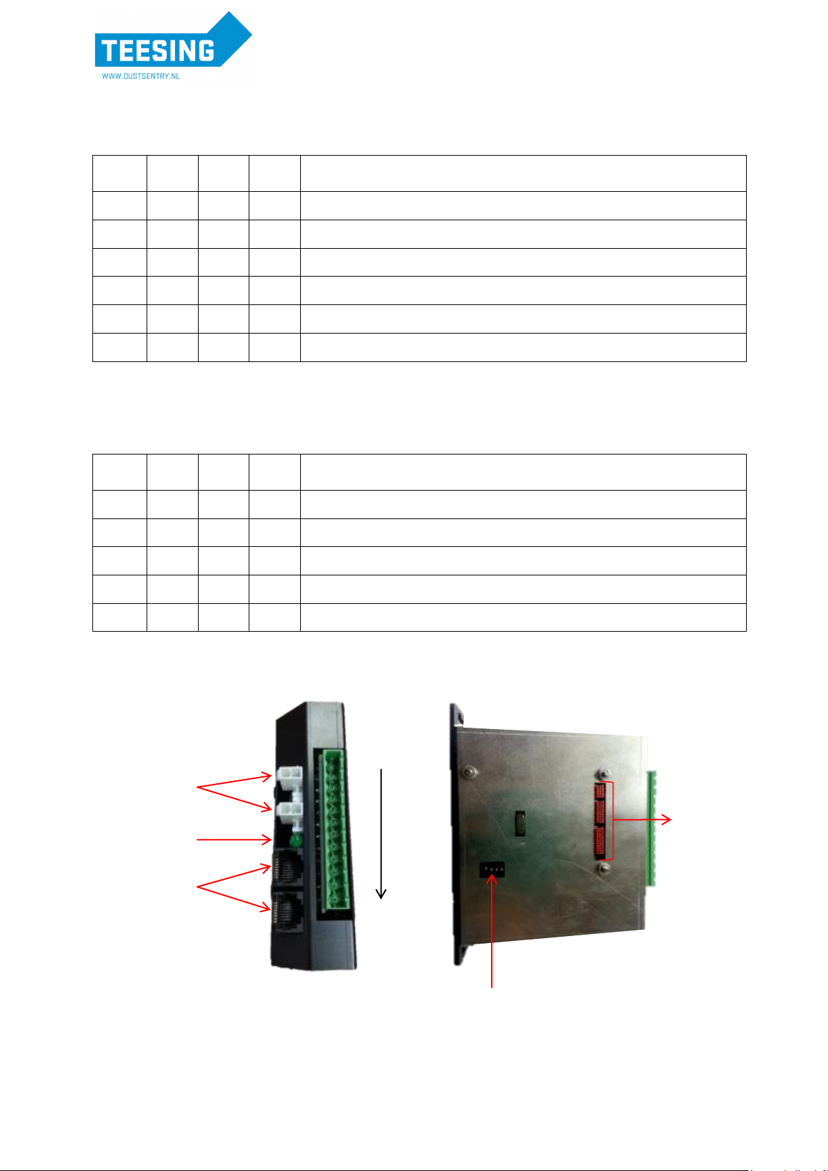
1.3. Control Module
The control module is the interface between the RS485 sensor bus and data communication links. It
contains a display, a SD data card which logs data, a RS232 serial connector for external
communication, a bus connector for internal communication with the sensor modules and a cable
connector for the Sensiron Humidity and Temperature sensor (if fitted).
The Dust Profiler is supplied with a RS232 to USB adapter fitted between the Control Module and an
external USB socket fitted at the base of the enclosure. This enables the user to perform a wide range
of functions over the USB connection, without needing to open the enclosure door, such as data
logging and various system checks using the supplied Aeroqual Dust Profiler PC software.
Note 1: The driver for the RS232 to USB adapter is in the USB stick which comes with the
instrument.
Note 2: The power to sensor and alarm relays are also attached to the control module base
plate.
Display
Front
6 way Alarm Relay
SD Card Slot
DB9 RS232
4 way T/RH
2 way Bus relay
activation
RJ45 RS485
Bus
2.1mm 12VDC relay
switched Power output
Top
Bottom
Off/On switch with LED.
Depress to power on (blue
LED on)
Controller 12VDC
power input
Programming Port
RS232
Firmware (V6.2+)
Programming Dip
Switch (position is
important)
Firmware (V6.2+)
WWW.DUSTSENTRY.NL | +31 70 413 70 50

1.4. Power Module
The Dust Sentry Pro internal power requires regulated 12 VDC to maintain a constant pump speed.
An external mains to 12VDC power supply (Meanwell HLG80-12A 60W 12V) is fitted on the outside
of the enclosure and this will allow connection to mains supply.
Note: If you wish to run the Dust Sentry Pro on solar power you will need to use a DC-DC
convertor in order to supply a regulated 12 VDC for the Dust Sentry Pro –refer to the
application notes on the website
1.5. Analogue Output Module (Optional)
The Dust Sentry has the option to integrate an ADAM 4021 Analogue Output Module into the system
to allow for the digital inputs of a chosen sensor to be converted to an analogue output. The analogue
output module receives the digital input via an RS485 interface and converts it to a 4-20mA and 2-
10V output. These outputs follow each other.
Outputs:
4mA (2V) = 0% of full scale value.
12mA (6V) = 50% of full scale value.
20mA (10V) = 100% of full scale value.
The module is easily configured via the Operations menu in the PC software and can convert to an
analogue output any chosen sensor already integrated in the Dust Sentry. The module uses the
logging period to calculate the reading, which is also set in the Operations menu. This differs from the
alarm relay, SMS and email which all use the averaged alarm period to calculate the reading. For
more information regarding the PC Software and setting up the analogue output module please refer
to Section 3.1.
1.6. Auxiliary Module (Optional)
The auxiliary module acts as an interface between third party sensors and the Dust Sentry Pro
communication bus. It is configured with different operating modes which can be selected by using
the dipswitches located on the side of the module. Aeroqual has integrated a number of third party
sensors and is able to supply the auxiliary module preconfigured for your sensors.
WWW.DUSTSENTRY.NL | +31 70 413 70 50
Firmware: AUX_MODULE_01.
Use for: Analogue inputs, Vaisala WXT520 weather, Gill Windsonic wind, Cirrus MK:427 noise.
1
2
3
4
Function
OFF
OFF
OFF
OFF
Default - standard Auxiliary module with AN1, AN2, Freq
ON
OFF
OFF
OFF
Vaisala WXT520 with RS232 communication + AN1, AN2, Freq
OFF
ON
OFF
OFF
Vaisala WXT520 with RS232 communication + Cirrus MK427 Noise
ON
ON
OFF
OFF
Wind Sonic with RS232 communication + AN1, AN2, Freq
OFF
OFF
ON
OFF
Wind Sonic with RS232 communication + Cirrus MK427 Noise
ON
OFF
ON
OFF
Cirrus MK427 Noise module only
Firmware: AUX_MODULE_02.
Use for: Analogue inputs, Met One MSO weather, Met One 034b wind, Cirrus MK:427 noise.
1
2
3
4
Function
OFF
OFF
OFF
OFF
Default - standard Auxiliary module with AN1, AN2, Freq
ON
OFF
ON
OFF
Cirrus MK427 Noise module only
OFF
ON
ON
OFF
Met One MSO with RS232 communication + Cirrus MK427 Noise
ON
ON
ON
OFF
Met One MSO with RS232 communication + AN1, AN2, Freq
OFF
OFF
OFF
ON
Met One 034B analogue module + Cirrus MK427 Noise
Pin 12
Pin 1
Status LED
12VDC Power
Connectors
RJ45 Connectors
for RS485 bus
Programming Dip
Switch
Programming
Port
WWW.DUSTSENTRY.NL | +31 70 413 70 50

1.6.1. Wiring of Auxiliary Module
PIN 1: GND
PIN 2: 12V FUSED
PIN 3: RESERVED
PIN 4: RESERVED
PIN 5: RX
PIN 6: TX
PIN 7: 0-5V IN
PIN 8: 4-20mA IN
PIN 9: FREQ IN
PIN 10: AGND
PIN 11: METONE 034B PWR
PIN 12: TIMED RELAY
Example of wiring:
Wind Sonic
(Pin 1) GND,
SIGNAL GND
(Pin 2) 12V
(Pin 5) RX
(Pin 6) TX
Vaisala
(Pin 1) GND for
operating, data &
heating
(Pin 2) 12V for
operating & heating
(Pin 5) RX
(Pin 6) TX
Met One MSO
(Pin 1) GND,
SIGNAL,
COMMON, SHIELD
(Pin 2) 12V
(Pin 5) RX
(Pin 6) TX
Met One 034B
(Pin 1) GND
(Pin 12) VCC
(Pin7) WD
(Pin 9) WS
Cirrus MK:427
(Pin 1) GND,
ACTUATOR GND
(Pin 2) 12V, LOOP
IN
(Pin 8) LOOP OUT
(Pin 12)
ACTUATOR IN
A programming port is also exposed through the side of the module to allow custom programs to be
loaded into the module.
Note: Aeroqual can supply a standard programming tool for distributors to reprogram the
auxiliary module to the specified requirements.
1.7. Gatetel GT-HE910_G Cellular Terminal (Optional)
Aeroqual can provide a Gatetel GT-HE910_G Cellular Terminal with GPS for remote data access
over GSM, GPRS or SMS networks. Please read the Gatetel GT-HE910_G Cellular Terminal manual
for detailed instructions on configuration and use. Further information can be found at:
http://gatetel.com/products.php?product=22
WWW.DUSTSENTRY.NL | +31 70 413 70 50

1.7.1. Specifications
1.8. Electrical Connections
RS485 Bus
The two wire RS485 bus connections are made using 20 cm CAT5 cables between the sensor
modules. The last module on the bus also has a blue termination dongle fitted.
Note: If the Analogue Output Module is fitted the termination dongle is not required.
12 VDC Power Bus
All modules inside the Dust Profiler operate from the 12VDC power. The power is supplied by a daisy
chain of black and red cables. A relay is activated by the Control Module on/off button to allow the
sensor bus to be powered.
12 VDC Power in
12 DC power is connected into the instrument at the terminal connector strip (“chock bloc”).
Features
Incorporates Telit HE910-DG
module
The Telit module handles all GSM/UMTS GPS
processing with PYTHON script
Frequency bands
GSM: 850/900/1800/1900MHz
UMTS/HSPA+: 800/850/900/1700/1900/2100MHz
Power supply
Single supply voltage 6V DC to 55V DC
connector 4 pin micro-fit 3mm
ADC and GPIO inputs
Two outputs optocouplers open collector drive 100ma
Two inputs optocouplers, 0-55v
One ADC 10 bit , 0-55V
connector 6 pin micro-fit 3mm
Communication
Modem Full RS232, connector D-Type 9pin (DB-9)
Modem USB, Connector USB Type B High retention
Antennas
GSM/UMTS GPS via SMA connectors
Mechanical Description
Weight
180g (6.35oz)
0.4 lb
Dimensions(max) L x W x H
83mm x 64mm x 34mm 3.26inch x 2.51inch x 1.33inch
Case material
Aluminium
Environmental Requirements
Operating temperature range
-20°C to +55°C
-4°F to 131°F
Ambient temperature
The module is fully functional in all the temperature range
and it fully meets the ETSI specifications.
-30°C to +70°C
-22°F to 158°F
The module is fully functional (*) in all the temperature
range. Temperatures outside of the range –20°C to +55°C
(-4°F to 131°F) might slightly deviate from ETSI
specifications.
Humidity
5% - 85%
WWW.DUSTSENTRY.NL | +31 70 413 70 50
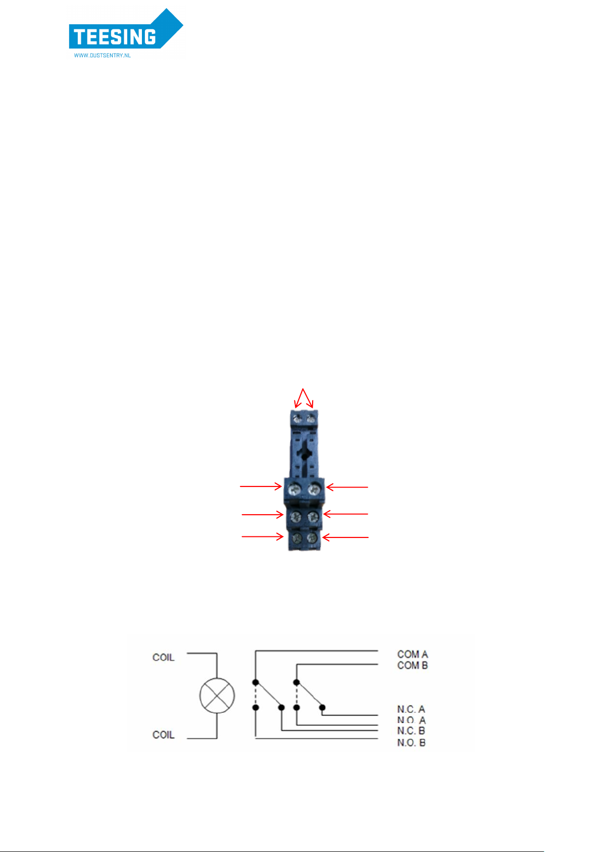
1.9. Alarm Relay
The Dust Profiler has a built in alarm relay function that is set up via the Operation Dialog in the PC
software (See Section 3.1.)
Relay Output: This is fitted as standard and is activated by “Enable Alarm Relay Output” tick box. If
the set point set in “Alarm trigger point” is exceeded the relay is activated. This can be used to
activate a siren or strobe or other peripheral devices. The relay remains activated until the measured
value drops below the reset point (expressed as a % of the trigger point). This is controlled via the
“Alarm reset point of trigger”. The “Alarm trigger point average period” determines the amount of time
that the concentration needs to be exceeding the trigger point before the relay is activated.
If “Active output on diagnostics” is selected the alarm will trigger upon sensor failure or sensor no
report. If not selected the alarms remain in the state they were in when the last valid reading was
logged.
The Alarm relay is energised by the Control Module in response to the alarm trigger point. The trigger
point is programmed into the Control Module via the Operation menu in the PC Software. The Alarm
Relay is a double pole; double throw type (see diagrams below). This allows the connection of two
different alarm signals –e.g. siren and strobe - that may have different power requirements.
The relay contacts rating: 2 x 5A @ 24VDC 220VAC.
Normally Open
A
Common
A
Normally Closed
A
Coil
Normally Open
B
Common
B
Normally Closed
B
Relay Internal Schematic
WWW.DUSTSENTRY.NL | +31 70 413 70 50
2.Assembly and Installation
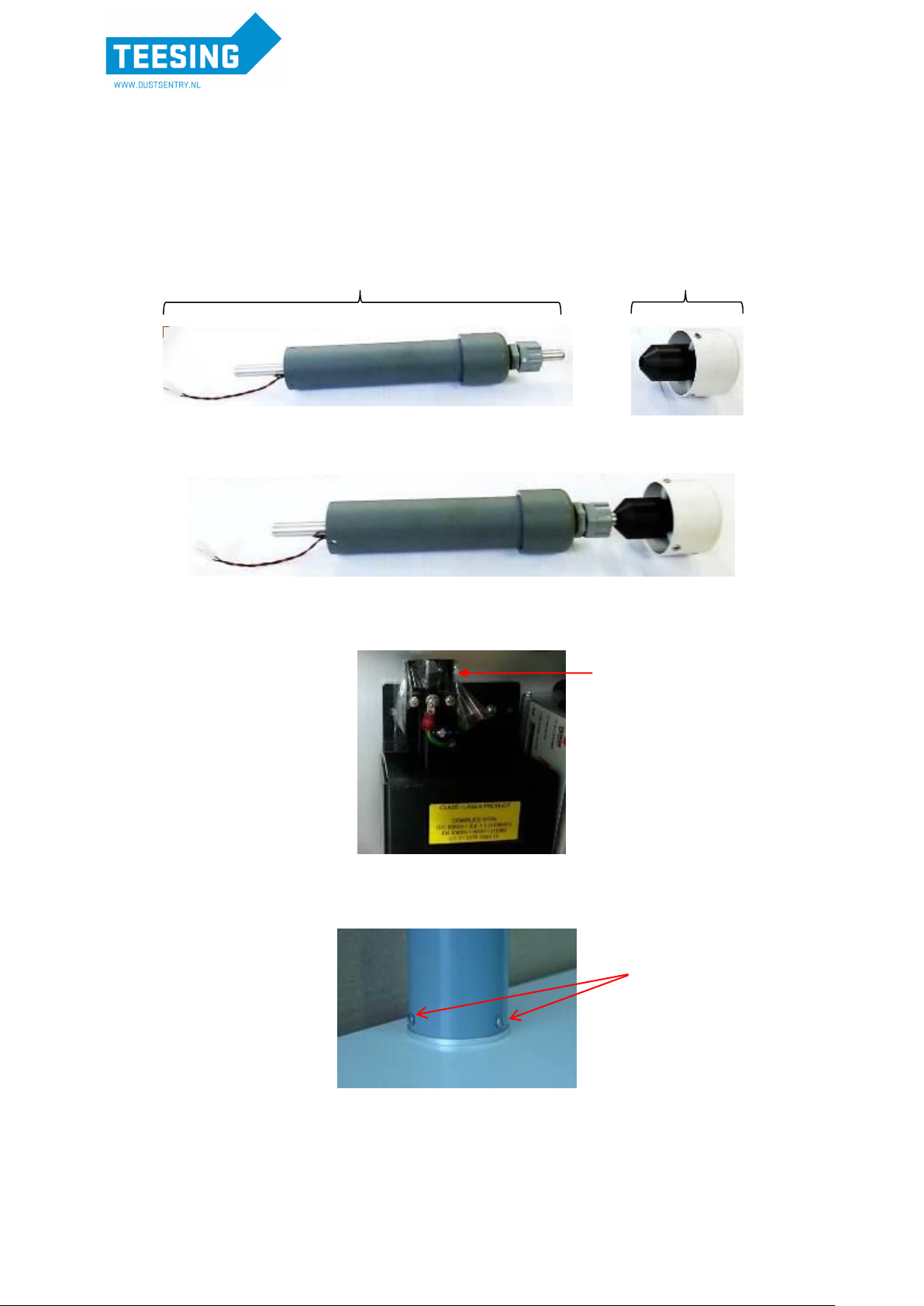
2.1. Assembly of heated inlet
Parts List:
A. Inlet Tube/Heater including power cable
B. TSP Inlet
i. Connect parts A and B
ii. Open door of enclosure and remove protective tape from the optical engine
iii. Insert Inlet Tube Assembly through base mount and fix the three mounting screws
Note: Ensure the power cable is fed through the inlet hole when connecting
B
A
Tape
Mounting
Screws
WWW.DUSTSENTRY.NL | +31 70 413 70 50

iv. Connect power to Inlet Tube/Heaterinside the enclosure
2.2. Connect Mains Power
Locate the power connector terminal which is situated outside the enclosure at the bottom.
The power supply will already be wired to the connector however the cable to connect to
mains power needs to be wired.
Caution: The high voltage mains supply must be wired by a certified electrician
in compliance with local electrical regulations.
3. Reconnect into the connector
ensuring the plugs are fitted securely
and the nut gland tightened.
Plug
Nut gland
Connector
Terminal block
Neutral
(Blue)
Earth
(Yellow/Green)
Live
(Brown)
2. Feed the power cable through the nut gland
plugs and connector and wire the cable to the
terminal block according to the diagram.
Note: To remove the terminal block from inside the connector unclick it from the casing by
turning it slightly then pull out
1. Unscrew the nut
gland to loosen the
terminal block and pull
connector apart
Power cable
from heated inlet
WWW.DUSTSENTRY.NL | +31 70 413 70 50

3.Dust Profiler Operation and Software
3.1. Getting Started
Computer Requirements
CD-ROM Drive or internet connection for software download
RS232 serial port or USB –RS232 serial port converter and USB cable (included)
Windows OS version 2000 or later
Minimum 100 Mb of spare hard drive space
Recommended 512 Mb RAM or more
Recommended 1 GHz processor speed or faster
1. Once the Dust Profiler is assembled and power is connected install the SD card into the control
module.
2. Start the Dust Profiler by pushing the on/off switch on the control module (See Section 1.3 for
location of On/Off switch)
3. Connect the instrument using a computer via the USB cable to the outside of the enclosure
4. Install Aeroqual Dust Monitor software. This can also be downloaded from the Aeroqual
website at www.aeroqual.com
5. Launch the Aeroqual Dust Monitor PC software.
a. Select to log in as either:
i. User (default password = “password”)
ii. Engineer (default password = “aeroqual”)
Note 1: User has access to most day to day functions on the
instrument. Engineer has access to all functions, including
diagnostic parameters (Sensor Module Settings and Sensor
Diagnostic View).
6. Configure the Dust Profiler instrument:
a. Select Setup Communication Port
b. Select Serial Port RS232 and the relevant Com port. Press OK when complete.
Note 2: The settings should be as seen below:
Note 3: To connect via the modem select TCP/IP Socket and enter the network IP address and
port number. If the PC is behind a proxy server this information needs to be added as well.
WWW.DUSTSENTRY.NL | +31 70 413 70 50

7. Check configuration
a. Select Setup Configuration
b. Check the correct sensors in the Dust Profiler have been configured.
c. These should match the sensors on the invoice and the sensors list in the instrument
logbook.
d. Click Save and Close.
Note 1: The more sensors configured, the larger the data file will be. Therefore, the
download time will be longer if using a remote connection.
Note 2: The Dust Profiler needs to be restarted after a parameter change.
8. Set Dust Profiler Real Time Clock
a. Click on Tools Update Real Time Clock (this will synchronise the Dust Profiler
clock with the computer date/time)
9. Configure the operations
a. Select Setup Operations.
b. Enter Data Logging Period
c. If the alarm relay is being used please check
“Enable Alarm Relay Output”
d. Select the output sensor and set the Alarm trigger
point. The alarm will go off when the concentration
reaches above the concentration set for the
selected sensor.
e. Select the reset point of trigger. This is the
percentage of the alarm trigger concentration at
which the alarm will reset.
f. Select the alarm trigger point average period. This
signifies the time interval at which the average is calculated for control of the alarm.
Note: The alarm average period must be greater than or equal to the data report
rate
WWW.DUSTSENTRY.NL | +31 70 413 70 50

g. If the analogue output module is being used please select “Enable 4-20 mA module”.
The module will follow the “Output Sensor” selected.
Note 1: If “Active on diagnostic” is set the analogue output will go to full scale upon No Report
or Sensor Failure condition. If not selected the analogue output will remain in the state it was
in when the last valid reading was logged.
Note 2: When the zero calibration is taking place the analogue output module does not update,
i.e. it remains in the state it was in immediately prior to the zero calibration. The module
remains in this state until the zero calibration is finished, then updates on the next valid
reading.
h. If the modem is being used please select “Use Gatetel modem”. Once this has been
checked the option to enable email and SMS message alerts will appear. (Refer to
Section 3.3. for information on connecting and using the modem features)
10. Start data-logging to confirm sensor communication and operation is correct.
a. Click Data Table Real Time to launch real time data table.
b. Click File Start Data logging. Data will start being displayed in Real Time Table.
3.2. System Checks
The following are a list of checks that should be performed to ensure the communications are working
correctly and the data is being logged properly. If there is an issue with one of these checks please
refer to Section 4 or contact Aeroqual for technical support.
1. With the Dust Profiler on, open the door and observe the display on the controller. This should
be scrolling with sensor readings.
2. Connect a USB cable to the port on the Dust Profiler enclosure and connect to a PC running
the Dust Monitor PC software. Confirm that you can communicate correctly with the
instrument.
3. Verify the Dust Profiler is data logging correctly to the SD card by clicking “File Download
Files” on the PC software. A daily log file (DLYYMMDD.AQL) containing the DUST
PROFILER sensor data is created each day. Also system events such as power on,
configuration updates, calibration events and system faults are logged to an EVENTLOG.AQL
file.
4. Confirm that the Real Time Clock setting and Configuration is correct.
5. Confirm all of the sensors installed in the Dust Profiler are logging onto the SD card log files
and in the real time table in the PC software. If not check that all the sensors are loaded in
Configuration menu
3.3. Modem configuration
If the Gatetel GT-HE910_G Cellular Terminal is purchased with the Dust Profiler it will need to be
configured using the PC software. Firstly, the modem requires a suitable SIM card (not supplied) that
matches the configuration.
Note: The SIM card needs to be pushed into the modem with the electronic tile facing upwards.
WWW.DUSTSENTRY.NL | +31 70 413 70 50

Configure
Select Setup Configure GPRS Modem
Enter the SIM card provider’s APN and username and password if applicable
Note: To use the modem in Server Mode requires an unrestricted APN that can accept
connections
Click save
Select Operating mode and select one of the operating modes
If using Dyn Org service:
Dyn server name is: members.dyndns.org
Dyn login name is: your account log in name
Dyn login password is: your account log in password
DynDNS host name is: the name you have configured for this instrument
Note: You must reboot the Dust Profiler after saving the Dyn Org parameters.
The modem has the following operating modes:
1. TCP Client Mode:
IP and domain name support
Destination address and port
Dust Profiler connects to chosen server and data accessed via server.
Note: There is no remote access to the Dust Profiler using this mode, except via the
designated server.
2. TCP Server Mode:
DDNS support for fixed or dynamic public IP addresses (using dyndns.org)
Optional firewall to restrict which IP addresses can connect to Dust Profiler
Set TCP port
WWW.DUSTSENTRY.NL | +31 70 413 70 50

3.3.1. Further information about IP address solutions using GPRS Systems
GPRS is a communication technology that allows data acquisition systems to overcome the difficulty
of cabling for wide area remote sites. GPRS applications are becoming more prevalent, but the
dynamic IP address issues associated with GPRS networking continue to frustrate system integrators.
The trouble with I/O devices with GPRS capability is that they receive a different IP address every
time they connect to the GPRS network.
Three distinct solutions have been developed to overcome this challenge:
Solution 1: Public Static IP Address
The first option is to obtain a public static IP address; some carriers (telecom service providers) can
assign a static IP address to a specific SIM card. This way, all the I/O devices will have their own
static IP address. The main benefit of this solution is that it behaves like a wired solution. However,
not all carriers offer this kind of service.
Solution 2: VPN Service Provided by Carrier/MVNO
A VPN (Virtual Private Network) is a secure LAN solution that groups specific devices together. The
VPN grouping concept solves the dynamic IP address issues and prevents unauthorized persons
from accessing the data. For this VPN solution, customers are required to buy one of a number of
different GPRS on-line services to be able to access a Virtual Private Network (VPN). When the
GPRS device dials up, the carrier will assign a private IP address which is on the same network
segment as the host and can maintain bi-directional communication using a polling architecture. Many
enterprise clients turn to mobile virtual network operators (MVNO). These MVNO’s acquire numerous
GPRS services and then rents them out to customers who are looking for a small number of IP
addresses.
Unfortunately, some countries do not have MVNOs, and some carriers do not provide VPN services.
For this reason, this solution may be unfeasible for some users.
Aeroqual has used www.wyless.com successfully to communicate with AQM instruments.
Solution 3: DDNS
Using dynamic IP addresses is often necessary since many ISPs do not provide static IP addresses.
The Dynamic Domain Name System (DDNS) is used to convert a device’s name into a dynamic IP
address so that remote devices can communicate with the control centre using a fixed domain name.
DDNS takes care of the Dynamic IP address of a device, and DNS the static IP address of a device.
With most remote GPRS devices, you need to apply for a hostname for each of the devices handled
by the DDNS server. When GPRS devices get an IP address from the carrier, they will automatically
connect to the GPRS network. Each time a GPRS device’s built-in DDNS client gets a new IP
address, it will send the IP address to the DDNS sever.
Aeroqual has integrated the “DynDNS Pro” service from http://dyn.com with your GateTel
modem. For a small annual fee you can configure up to 30 host names to use with up to 30
modems.
3.3.2. Email Message
This function assumes the modem is fitted and correctly configured. It is activated by the “Enable
Email Alert” tick box under Operations. Up to 5 Email recipients can be connected at once.
WWW.DUSTSENTRY.NL | +31 70 413 70 50
Table of contents
Popular Measuring Instrument manuals by other brands

Bosch
Bosch GRL 250 HV Original instructions

Endress+Hauser
Endress+Hauser RID14 Brief operating instructions

APOELMOS
APOELMOS AP11-34 Series manual

Omega Engineering
Omega Engineering FMA-1600A Series user guide

Winters
Winters LCD11 Series Operation manual

Steinberg Systems
Steinberg Systems SBS-SM-130C user manual


