TEH LP820 User manual

Tools for Every Home
Cordless Planer
LP820

Battery
Release
Button
Battery
On/Off Switch
Lock-off Lever
Depth Adjustor
Model
Rated Voltage
Motor
No-Load Speed
Planning Width
Planning Depth
Rabbeting Depth
Compatible Battery
LP820
DC 20V
Brush
15000r/min
82mm
0-2mm
0-10mm
LB4.0Ah
12

34
ELECTRICAL SAFETY
a) Power tool plugs must match the outlet. Never modify the plug in any way. Do not use any
adapter plugs with earthed (grounded) power tools. Unmodified plugs and matching outlets will
reduce risk of electric shock.
b) Avoid body contact with earthed or grounded surfaces such as pipes, radiators, ranges and
refrigerators. There is an increased risk of electric shock if your body is earthed or grounded.
c) Do not expose power tools to rain or wet conditions. Water entering a power tool will increase
the risk of electric shock.
d) Do not abuse the cord. Never use the cord for carrying, pulling or unplugging the power tools.
Keep cord away from heat, oil, sharp edges or moving parts. Damaged or entangled cords
increases the risk of electric shock.
PERSONAL SAFETY
a) Stay alert, watch what you are doing and use common sense when operating a power tool. Do
not use a power tool while you are tired or under the influence of drugs, alcohol or medication. A
moment of inattention while operating power tools may result in serious personal injury.
b) Use safety equipment. Always wear eye protection. Safety equipment such as dust mask, non-
skid safety shoes, hard hat, or hearing protection used for appropriate conditions will reduce the
risk of personal injuries.
c)Prevent unintentional starting. Ensure the switch is in the off-position before connecting to power
source and/or battery pack, picking up or carrying the tool.
Carrying power tools with your finger on the switch or energizing power tools that have the switch
on invites accidents.
d) Remove any adjusting key or wrench before turning the power tool on. A wrench or a key to a
rotating part of the power tool may result in personal injury.
e) Do not overreach. Keep proper footing and balance at all times. This enables better control of
the power tool in unexpected situations.
f) Dress properly. Do not wear loose clothing or jewellery. Keep your hair, clothing and gloves
away from moving parts. Loose clothes, jewellery or long hair can be caught in moving parts.
g) Store idle power tools out of the reach of children and do not allow persons unfamiliar with the
power tool or these instructions to operate the power tool. Power tools are dangerous in the hands
of untrained users.
h)Maintain power tools. Check for misalignment or binding of moving parts, breakage of parts
and any other condition that may affect the power tool’s operation. If damaged, have the power
tool repaired before use. Many accidents are caused by poorly maintained power tools.
e) When operating a power tool outdoors, use an extension cord suitable for outdoor use. Use of a
cord suitable for outdoor use reduces the risk of electric shock.
f) If operating a power tool in a damp location is unavoidable, use a residual current device (RCD)
protected supply. Use of an RCD reduces the risk of electric shock.

l) Keep cutting tools sharp and clean. Properly maintained cutting tools with sharp cutting edges
are less likely to bind and are easier to control.
n) Use the power tool, accessories and tool bits etc. in accordance with these instructions, taking
into account the working conditions and the work to be performed. Use of the power tool for
operations different from those intended could result in a hazardous situation.
Have your power tool serviced by a qualified repair person using only identical replacement parts.
This will ensure that the safety of the power tool is maintained.
SERVICE
USE AND HANDLING OF THE CORDLESS
ELECTRICAL POWER TOOL
a) Charge a rechargeable battery unit using only the charger recommended by the manufacturer.
Chargers are often designed for a particular type of rechargeable battery unit. There is the danger
of fire if other types of rechargeable battery units are used.
b) Only the rechargeable battery units supplied are to be used with an electrical power tool. The
use of other rechargeable battery units may lead to the danger of injury or fire.
c) When they are not being used, store rechargeable
battery units away from paperclips, coins, keys, nails, screws or other small metal objects that
could cause the contacts to be bridged. Short-circuiting the contacts of a rechargeable battery
unit may result in heat damage or fire.
d) Fluids may leak out of rechargeable battery units if they are misused. If this happens, avoid
contact with the fluid. If contact occurs, flush the affected area with water. Seek additional medical
help if any of the fluid gets into your eyes. Escaping battery fluid may cause skin irritation or burns.
a) Ensure that the device is switched off before inserting the battery. Inserting a battery into a
power tool that is switched on may result in accidents.
b) Recharge the batteries indoors only because the battery charger is designed for indoor use
only.
c) To reduce the electric shock hazard, unplug the battery charger from the mains before cleaning
the charger.
d) Do not subject the battery to strong sunlight over long periods and do not leave it on a heater.
Heat damages the battery and there is a risk of explosion.
e) Allow a hot battery to cool before charging.
f) Do not open up the battery and avoid mechanical damage to the battery. Risk of short circuit
and fumes may be emitted that irritate the respiratory tract. Ensure fresh air and seek medical
assistance in the event of discomfort.
g) Do not use non-rechargeable batteries!
SPECIAL SAFETY DIRECTIONS FOR BATTERY-OPERATED TOOLS
a) This device can be used by children aged 8 and over and by people with reduced physical,
sensory or mental capacities or with a lack of experience or knowledge, if they are supervised or
have been instructed regarding safe use of the device and understand the resulting risks. Children
are not permitted to play with the device. Cleaning and user maintenance are not to be undertaken
by children without supervision.
b) Children should be supervised to ensure that they do not play with the appliance.
c) To charge the battery, use only the charger supplied. Risk of fire and explosion. This ensures
that the safety of the device is maintained.
d) Before each use, check the charger, cable and plug and have them repaired by qualified
professionals and only with original parts. Do not use a defective charger and do not open it up
yourself. This ensures that the safety of the device is maintained.
CORRECT HANDLING OF THE BATTERY CHARGER
56

e) Connect the charger only to a socket with an earth. Ensure that the mains voltage matches the
specifications on the charger rating plate. Risk of electric shock.
f) Disconnect the charger from the mains before closing or opening connection to the battery /
power tool / device.
g) Keep the charger clean and away from wet and rain. Do not use the charger outdoors. Dirt and
the entry of water increase the risk of electric shock.
h) Operate the charger only with the appropriate original batteries. Charging other batteries may
result in injuries and risk of fire.
I) Avoid mechanical damage to the charger. This can result in internal short circuits.
j) Do not operate the charger on a combustible surface (e.g. paper, textiles). Risk of fire due to
heating during charging.
k) If the power cable for this equipment is damaged, it must be replaced by the manufacturer, a
customer service agent of the same or a similarly qualified person in order to prevent hazards.
l) The battery of the appliance is not fully charged at the time of delivery. It therefore needs to be
fully recharged before you use it for the first time. For the first recharge cycle we recommend that
you charge the battery for about 1 hour. Slot the battery into the base and plug the battery charger
into a mains outlet.
m) When the battery is fully charged, unplug the charger from the mains and from the appliance.
Charging time is approx. 1
hour.
n) Do not charge the battery continuously since this may damage the battery cells.
Note: Repeatedly charging small capacities may damage the battery cells. Recharge the battery
only if the appliance is becoming slow.
o) Do not use the charger to charge non-rechargeable batteries.
Even if properly operating and handling this electric tool, some residual risks will remain. Due to its
construction and build, this electric tool may present the following hazards:
RESIDUAL RISKS
During operation, this electric tool generates an electromagnetic field which, under
certain circumstances, may impair the functionality of active or passive medical
implants. To reduce the risk of serious or lethal injuries, we recommend that persons
with medical implants consult their doctor and the manufacturer of their medical
implant before operating the machine.
WARNING
a) Cuts
b) Ear damage if working without ear protection.
c) Damage to your health caused by swinging your hands and arms when operating the appliance
for longer periods of time or if the unit is not held or maintained properly.
1. Wait for the cutter to stop before setting the tool down. An exposed rotating cutter may engage
the surface leading to possible loss of control and serious injury.
2. Use clamps or another practical way to secure and support the workpiece to a stable platform.
Holding the work by your hand or against the body leaves it unstable and may lead to loss of
control.
3. Rags, cloth, cord, string and the like should never be left around the work area.
4. Avoid cutting nails. Inspect for and remove all nails from the workpiece before operation.
5. Use only sharp blades. Handle the blades very carefully.
6. Be sure the blade installation bolts are securely tightened before operation.
7. Hold the tool firmly with both hands.
8. Keep hands away from rotating parts.
9. Before using the tool on an actual workpiece, let it run for a while. Watch for vibration or
wobbling that could indicate poor installation or a poorly balanced blade.
CORDLESS PLANER SAFETY WARNINGS
78

910
10. Make sure the blade is not contacting the workpiece before the switch is turned on.
11. Wait until the blade attains full speed before cutting.
12. Always switch off and wait for the blades to come to a complete stop before any adjusting.
13. Never stick your finger into the chip chute. Chute may jam when cutting damp wood. Clean
out chips with a stick.
14. Do not leave the tool running. Operate the tool only when hand-held.
15. Always change both blades or covers on the drum, otherwise the resulting imbalance will
cause vibration and shorten tool life.
16. Use only blades specified in this manual.
17. Always use the correct dust mask/respirator for the material and application you are working
with.
Always be sure that the tool is switched off and the battery cartridge is removed
before adjusting or checking function on the tool.
WARNING
INSTALLATION INSTRUCTION
Always be sure that the tool is switched off and thebattery cartridge is removed
before carrying outany work on the tool.
WARNING
REMOVING OR INSTALLING PLANER BLADES
1. Tighten the blade installation bolts carefully when attaching the blades to the tool.
A loose installation bolt can be dangerous. Always check to see they are tightened
securely.
2. Handle the blades very carefully. Use gloves or rags to protect your fingers or
hands when removing or installing the blades.
3. Use only the wrench provided to remove or install the blades. Failure to do so
may result in over tightening or insufficient tightening of the installation bolts. This
could cause an injury.
WARNING
FOR TOOL WITH CONVENTIONAL PLANER BLADES
1. Socket wrench
2. Bolt
3. Loosen
4. Tighten
1. Bolts
2. Drum
3. Planer blade
4. Drum cover
5. Adjusting plate
1. Inside edge of gauge plate
2. Blade edge 3. Planer blade
4. Adjusting plate 5. Screws
6. Heel
7. Back side ofgauge base
8. Gauge plate 9. Gauge base
2
1
3
4
2
1
3
4
5
1
2
3
4
5
6
78
9

11 12
1. To remove the blades on the drum, unscrew the installation bolts with the socket wrench. The
drum cover comes off together with the blades.
2.To install the blades, first clean out all chips or foreignmatter adhering to the drum or blades.
Use blades of thesame dimensions and weight,or drumoscillation/vibration will result, causing
poor planingaction and, eventually, tool breakdown.
3. Place the blade on the gauge base so that the blade edge is perfectly flush with the inside edge
of the gauge plate. Place the adjusting plate on the blade, then simply press in the heel of the
adjusting plate flush with the back side of the gauge base and tighten two screws on the adjusting
plate. Now slip the heel of the adjusting plate into the drum groove, then fit the drum cover on it.
4. Tighten all the installation bolts evenly and alternately with the socket wrench.
5. Repeat the above procedures for the other blade.
FOR TOOL WITH MINI PLANER BLADES
1. Socket wrench
2. Bolt
3. Loosen
4. Tighten
1. Remove the existing blade, if the tool has been inuse,
carefully clean the drum surfaces and thedrum cover. To
remove the blades on the drum,unscrew the three
installation bolts with the socket wrench. The drum cover
comes off together withthe blades.
2. To install the blades, loosely attach the adjusting plate to the
set plate with the pan head screws and set the mini planer
blade on the gauge base so that the cutting edge of the blade
is perfectly flush with the inside flank of the gauge plate.
3. Set the adjusting plate/set plate on the gauge base so that
the planer blade locating lugs on the set plate rest in the mini
planer blade groove, then press in the heel of the adjusting
plate flush with the back side of the gauge base and tighten
the pan head screws.
4. It is important that the blade sits flush with the inside flank of
the gauge plate, the planer blade locating lugs sit in the blade
groove and the heel of the adjusting plate is flush with the
back side of the gauge base. Check this alignment carefully to
ensure uniform cutting.
5. Slip the heel of the adjusting plate into the grooveof the
drum.
1. Mini planer blade
2. Groove
3. Set plate
4. Hex. flange head bolts
5. Drum cover
6. Drum
7. Adjusting plate
6. Set the drum cover over the adjusting plate/set plate and screw in the three hex flange head
bolts so that a gap exists between the drum and the set plate to slide the mini planer blade into
position. The blade will be positioned by the planer blade locating lugs on the set plate.
7. The blade's lengthwise adjustment will need to be manually positioned so that the blade ends
are clear and equidistant from the housing on one side and the metal bracket on the other.
8. Tighten the three hex flange head bolts (with the socket wrench provided) and rotate the drum
to check clearances between the blade ends and the tool body.
9. Check the three hex flange head bolts for final tightness.
10. Repeat procedures 1 - 9 for the other blade.
2
1
3
4
1. Pan head screw
2. Adjusting plate
3. Planer blade locating lugs
4. Gauge plate
5. Heel ofadjusting plate
6. Set plate
7. Inside flank ofgauge plate
8. Gauge base
9. Back side ofgauge base
10. Mini planer blade
1
2
3
4
5
6
7
8
9
10
1
2
3
74
5
6
FOR THE CORRECT PLANER BLADE SETTING
Your planing surface will end up rough and uneven, unless the blade is set properly and securely.
The blade must be mounted so that the cutting edge is absolutely level, that is, parallel to the
surface of the rear base. Refer to some examples below for proper and improper settings.
A Front base (Movable shoe)
B Rear base (Stationary shoe)
Correct setting
Nicks in surface
Gouging at start
Gouging at end
Although this side view cannot show it, the edges
of the blades run perfectly parallel to the rear base
surface.
Cause: One or both blades fails tohave edge
parallel to rearbase line.
Cause: One or both blade edgesfails to protrude
enough inrelation to rear base line.
Cause: One or both blade edges protrudes too far
in relation to rear base line.
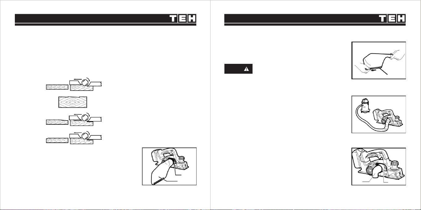
DUST BAG (ACCESSORY)
Remove the chip cover and install the nozzle (optional
accessory). Attach the dust bag onto the nozzle .Thenozzle
is tapered. When attaching the dust bag, push itonto the
nozzle firmly as far as it will go to prevent it fromcoming off
during operation.
For tool without nozzle
1. Nozzle 2. Dust bag
When the dust bag is about half full, remove the dust bag
from the tool and pull the fastener out. Empty the dust bag of
its contents, tapping it lightly so as to remove particles
adhering to the insides which might hamper further collection.
1. Fastener
CONNECTING A VACUUM CLEANER
For tool without nozzle: When you wish to perform clean
planing operation,connect a vacuum cleaner to your tool.
Beforeconnecting the vacuum cleaner, remove the chip cover
from the tool. Then connect a hose of the vacuumcleaner to
the nozzle (optional accessory) as shown inthe figures.
For tool with nozzle: When you wish to perform clean planing
operation, connect a vacuum cleaner to your tool. Then
connect a hose of the vacuum cleaner to the nozzle as shown
in the figures.
Use of elbow allows change of chip discharge direction to
perform cleaner work
For tool without nozzle: Remove the chip cover and install
the nozzle (optional accessory). Attach the elbow (optional
accessory) on the nozzle of the tool by just slipping on it. To
remove it, just pull it out.
For tool with nozzle: Attach the elbow (optional accessory)
on the nozzle of the tool by just slipping on it. To remove it, just
pull it out.
ELBOW (OPTIONAL ACCESSORY)
1. Elbow 2. Nozzle
If you connect a vacuum cleaner to
this tool,more efficient and cleaner
operations can be performed.
NOTE
1
2
AB
AB
AB
1
12
13 14

OPERATION INSTRUCTION
Depth of cut may be adjusted by simply turning the knob on
the front of the tool so that the pointer points the desired
depth of cut.
ADJUSTING DEPTH OF CUT
1. Pointer 2. Knob
Before installing the battery cartridge into the tool,
always check to see that the switch trigger
actuates properly and returns to the "OFF" position
when released.
Do not pull the switch trigger hard without pressing
the lock off lever. This can cause switch breakage.
WARNING
1. Lock-off Lever 2. Switch Trigger
To prevent the switch trigger from being accidentallypulled,
a lock off lever is provided. To start the tool, slidethe lock-
off lever and pull the switch trigger. Release theswitch
trigger to stop.
SWITCH ACTION
1. For your safety, this tool is equipped with lock-off lever which prevents the tool
from unintended starting. never use the tool if it runs when you simply pull the
switch trigger without pressing the lock-off lever. Return tool a service center for
proper repairs before further usage.
2. Never tape down or defeat purpose and function of lock -off lever.
WARNING
1. Planer blade 2. Rear base3. Foot
To prevent the switch trigger from being accidentally pulled, a lock. off button is provided.
To start the tool, depress the lock-off button and pull the switch trigger. Release the switch trigger
to stop.
After a cutting operation, raise the back side of the tooland
a foot comes under the level of the rear base. Thisprevents
the tool blades to be damaged.
FOOT
1
2
12123
15 16

First, rest the tool front base flat upon the workpiece surface
without the blades making any contact. Switch on and wait until
the blades attain full speed. Then move the tool gently forward.
Apply pressure on the front of tool at the start of planing, and at
the back at the end of planing. Planing will be easier if you
incline the workpiece in stationary fashion, so that you can
plane somewhat downhill.
The speed and depth of cut determine the kind of finish.
The power planer keeps cutting at a speed that will not result in
jamming by chips. For rough cutting, the depth of cut can be
increased, while for a good finish you should reduce the depth
of cut and advance the tool more slowly.
1. Start 2. End
SHIPLAPPING (RABBETING)
To make a stepped cut as shown in the figure, use theedge fence (guide rule) which is obtained
as accessory.
PLANING OPERATION
Hold the tool firmly with one hand on the knob and theother hand on the switch handle when
performing thetool.
Draw a cutting line on the
workpiece. Insert the edge
fence into the hole in the front
of the tool. Align the blade
edge with the cutting line.
1. Screw
2. Edge fence
Adjust the edge fence until it
comes in contact with the
side of the workpiece, then
secure it by tightening the
screw.
When planing, move the tool
with the edge fence flush
with the side of the
workpiece. Otherwise uneven
planingmay result.
Maximum shiplapping
(rabbeting) depth is 9 mm.
To make a chamfering cut as shown in the figure, align the "V" groove in the front base with the
edge of the workpiece and plane it.
CHAMFERING
You may wish to add to the length of the fence byattaching an extra piece ofwood. Convenient
holes areprovided in the fence for thispurpose, and also forattaching an extension guide.
1
2
1. Blade edge 2. Cutting line
1
2
1
2
17 18

19 20
MAINTENANCE
Always be sure that the tool is switched off and thebattery cartridge is removed
before attempting toperform inspection or maintenance.
Never use gasoline, benzine, thinner, alcohol or the like. Discoloration, deformation
or cracks may result.
WARNING
Immerse the dressing stone in water for 2 or 3 minutes
before sharpening. Hold the holder so that the both blades
contact the dressing stone for simultaneous sharpening at
the same angle.
Remove and check the carbon brushes regularly.
Replace when they wear down to the limit mark. Keep the
carbon brushes clean and free to slip in the holders.Both
carbon brushes should be replaced at the sametime. Use
only identical carbon brushes
REPLACING CARBON BRUSHES
Use a screwdriver to remove the brush holder Take out the
worm carbon brushes, insert the new ones and secure the
brush holder caps.
To maintain product SAFETY and RELIABILITY, repairs any
other maintenance or adjustment should be formed by
TEH Authorized Service Centers, always using TEH
replacement parts.
Always keep your blades sharp for the best performance
possible. Use the sharpening holder (optional accessory) to
remove nicks and produce a fine edge.
For conventional blades only
SHARPENING THE PLANER BLADES
1. Sharpening holder
1
First, loosen the two wing nuts on the holder
and insertthe blades (A) and (B), so that they
contact the sides (C)and (D). Then tighten the
wing nuts.
1. Wing nut
2. Blade (A)
3. Blade (B)
4. Side (D)
5. Side (C)
1
2
3
4
5
1. Limit mark
1
1. Brush holdercap 2. Screwdriver
12

WARRANTY CARD
ladies/gentlemen: employer:
contact number: fax number:
contact address:
warranty record:
post code:
IMPORTANT NOTE
1. The invoice and warranty card must be presented at the time of warranty.
2. The fuselage number on the invoice is the same as the fuselage number on the warranty card.
3. Once this warranty card is issued, if it is lost, it will not be reissued. Please keep it properly.
Note: The company reserves the right to amend the above provisions and has the final interpretation right in the
case that the warranty service does not violate national laws.
Dear customers, the warranty service for purchasing TEH products is as follows:
Under normal use, within one year from the date of purchase. It is guaranteed that the damage
is caused by the quality of the tool.
The following conditions occur during the warranty period, not covered by the warranty:
a. Any valid legal document (single ticket) certifying the date of purchase
b. Any damage caused by natural wear and overload
c. Any damage caused by the use of low-priced inferior accessories
d. Any damage caused by improper carrying, transportation or storage
e. Any product that has been opened, repaired, replaced, or modified by itself
f. Any damage caused by misuse, beyond the scope of use of the tool,
and failure to use and maintain in accordance with the instructions
21 22
Table of contents


