Teich-Aire KM Series User manual

Owners Manual
KM Series Teich-AireTM
Rocking Piston Oil-less Compressors
Contents
Important Product Use Information . . . . . .pg2
Installation Requirements . . . . . .pg2
Plumbing . . . . . .pg2
Electrical . . . . . .pg3
Operation . . . . . .pg4
Maintenance . . . . . .pg4
Troubleshooting . . . . . .pg5
Warranty . . . . . .pg6
Rev. 04/17/13
Kasco Marine, Inc.
800 Deere Rd.
Prescott, WI 54021
U.S.A.
PH 00+1+715+262+4488
FAX 00+1+715+262+4487
www.kascomarine.com
www.teich-aire.com
Teich-Aire™

2
Thank you for purchasing this Teich-Aire compressor.
It is manufacturered to the highest standards using
quality materials. Please follow all recommended
maintenance, operational and safety instructions and
you will receive years of trouble free service.
IMPORTANT: PLEASE READ THIS
MANUAL AND SAVE FOR FUTURE
REFERENCE.
To facilitate future spare parts ordering or technical
assistance, please copy the details from the compressor
nameplate onto this page and save for future reference.
Rocking Piston Compressor
Model: S/N:
Air
Flow cfm Max
Pressure psi
Voltage V Hz Amp
Phase Single Kw RPM
Important Product Use Information
• To avoid accident, do not use compressor in any
way other than described in this manual.
• Pump only clean, dry air.
• Operate at 32°F – 104° (0°C – 40°C)
• Protect unit from dirt and moisture
• Donotpumpammableorexplosivegasesoruse
in an environment that contains such gases.
• Protect all surrounding items from exhaust air.
Exhaust air can become very hot.
• Corrosive gases and particulate material will
damage unit. Water vapor, oil-based contaminants
orotherliquidsmustbelteredout.
• This pump is oil-less and requires no lubrication.
Installation Requirements
• Correct installation is your responsibility. Make
sure you have the proper installation conditions
and that installation clearances do not block air
ow.
• Compressor needs to be installed in a clean, dry
location.
• Compressor needs to be protected from dirt and
moisture and from the outdoor environment such
asrain,snowandooding.
• Ambient air temperature (temperature readings
taken 4” away from any surface of the compressor)
must not exceed 104°F (40°C).
• Adequateventilationandcoolingair(ow
across the compressor) must be provided to keep
the compressor from overheating and causing
premature damage.
• Mounting the compressor to a stable, rigid
operating surface and using shock mounts will
reduce noise and vibration.
• Kasco Marine offers a simple, durable bracket
accessory that will allow you to easily mount
thecompressortoawall,oororbench.Please
contact your local Kasco distributor and ask for the
Universal Compressor Mount Kit Model 771160.
Motor Control
It is your responsibility to contact a qualified
electrician and assure that the electrical installation is
adequate and in conformance with all national and local
codes and ordinances. The metal capacitor must be
grounded.
Determine the correct overload setting required to
protect the motor (see motor starter manufacturer’s
recommendations). Select fuses, motor protective
switches or thermal protective switches to provide
protection. Fuses act as short circuit protection for the
motor, not as protection against overload. Incoming
line fuses must be able to withstand the motor’s
starting current. Motor starters with thermal magnetic
overload or circuit breakers protect motor from
overload or reduced voltage conditions.
The wiring diagram supplied with the product provides
required electrical information. Check that power
source is correct to properly operate the dual-voltage
motors.
Your safety and the safety of others
is extremely important.
We have provided many important safety messages in
this manual and on your product. Always read and
obey all safety messages.
This is the safety alert symbol. This symbol
alerts you to hazards that can kill or hurt you and
others. The safety alert symbol and the words
“DANGER” and “WARNING” will precede all safety
messages. These words mean:
You will be killed or seriously injured if you donʼt follow
instructions.
You can be killed or seriously injured if you donʼt follow
instructions.
All safety messages will identify the hazard, tell you
how to reduce the chance of injury, and tell you what
can happen if the safety instructions are not followed.
Correct installation is your responsibility. Make sure you
have the proper installation conditions and that
installation clearances do not block air flow.
Blocking air flow over the product in any way can cause
the product to overheat.
Mounting
This product can be installed in any orientation.
Mounting the product to a stable, rigid operating
surface and using shock mounts will reduce noise and
vibration.
INSTALLATION
Accessories
The product’s external intake and exhaust muffler will
provide adequate filtration in most applications. Check
filters periodically and replace when necessary. Consult
your Gast Distributor/Representative for additional filter
recommendations.
WARNING
DANGER
Disconnect electrical power at the circuit breaker
or fuse box before installing this product.
Install this product where it will not come into
contact with water or other liquids.
Install this product where it will be weather
protected.
Electrically ground this product.
Failure to follow these instructions can result in
death, fire or electrical shock.
WARNING
Electrical Shock Hazard
Plumbing
Remove plugs from the IN and OUT ports. Connect
with pipe and fittings that are the same size or larger
than the product’s threaded ports. Be sure to connect
the intake and exhaust plumbing to the correct inlet
and outlet ports. Ports will not support plumbing.
Install relief valves and gauges at inlet or outlet or both,
to monitor performance. Check valves may be required
to prevent back streaming through the pump.
Electrical Connection
This product must be properly grounded.
Do not modify the plug provided. If it will not
fit the outlet, have the proper outlet installed
by a qualified electrician.
If repair or replacement of the cord or plug is
necessary, do not connect the grounding wire
to either flat blade terminal. The wire with
insulation that is green or green with yellow
stripes is the grounding wire.
Check the condition of the power supply wiring.
Do not permanently connect this product to
wiring that is not in good condition or is
inadequate for the requirements of this product.
Failure to follow these instructions can result in
death, fire or electrical shock.
WARNING
Electrical Shock Hazard
Plumbing
Remove plugs as necessary from the IN and OUT
ports.Connectwithpipeandttingsthatarethesame
size or larger than the products threaded ports. Be
sure to connect the intake and exhaust plumbing to the
correct inlet and outlet ports. Ports will not support
plumbing.
Installairlterinoneinletport.Itisrecommendedto
install a pressure relief valve in an outlet port to bleed
off excess pressure in case of a blocked line. Check
valvesmayberequiredtopreventbackowthrough
the compressor.
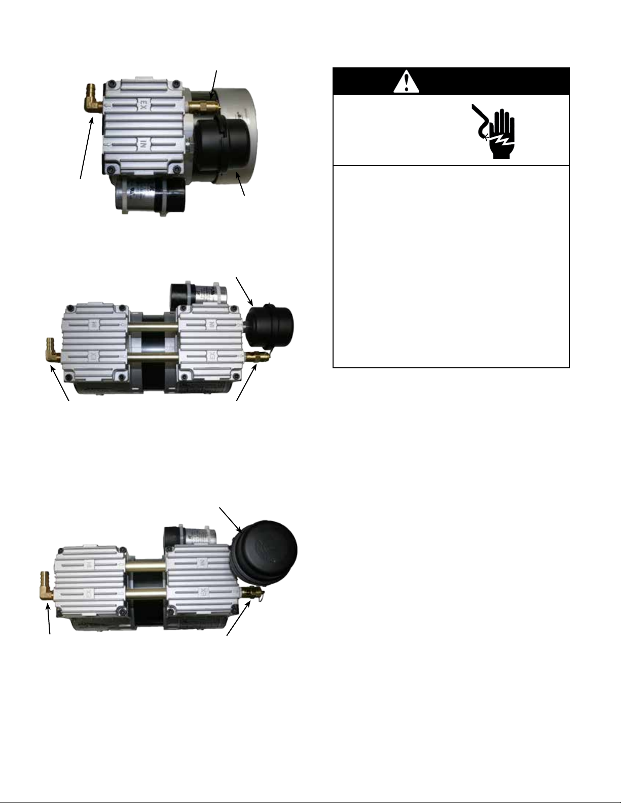
3
EX
IN
Barb
Fitting Air
Filter
pressure
relief valve
EX
KM-60C
KM-60HC
EX
IN
Barb
Fitting
Air
Filter
pressure
relief valve
EX
KM-120C
KM-120HC
EX
IN
Barb
Fitting
Air Filter
connected to
brasstting
pressure
relief valve
EX
KM-200C
KM-200HC
Electrical
Motor Control
It is your responsibility to contact a qualified
electrician and assure that the electrical installation is
adequate and in conformance with all national and local
codes and ordinances. The metal capacitor must be
grounded.
Determine the correct overload setting required to
protect the motor (see motor starter manufacturer’s
recommendations). Select fuses, motor protective
switches or thermal protective switches to provide
protection. Fuses act as short circuit protection for the
motor, not as protection against overload. Incoming
line fuses must be able to withstand the motor’s
starting current. Motor starters with thermal magnetic
overload or circuit breakers protect motor from
overload or reduced voltage conditions.
The wiring diagram supplied with the product provides
required electrical information. Check that power
source is correct to properly operate the dual-voltage
motors.
Your safety and the safety of others
is extremely important.
We have provided many important safety messages in
this manual and on your product. Always read and
obey all safety messages.
This is the safety alert symbol. This symbol
alerts you to hazards that can kill or hurt you and
others. The safety alert symbol and the words
“DANGER” and “WARNING” will precede all safety
messages. These words mean:
You will be killed or seriously injured if you donʼt follow
instructions.
You can be killed or seriously injured if you donʼt follow
instructions.
All safety messages will identify the hazard, tell you
how to reduce the chance of injury, and tell you what
can happen if the safety instructions are not followed.
Correct installation is your responsibility. Make sure you
have the proper installation conditions and that
installation clearances do not block air flow.
Blocking air flow over the product in any way can cause
the product to overheat.
Mounting
This product can be installed in any orientation.
Mounting the product to a stable, rigid operating
surface and using shock mounts will reduce noise and
vibration.
INSTALLATION
Accessories
The product’s external intake and exhaust muffler will
provide adequate filtration in most applications. Check
filters periodically and replace when necessary. Consult
your Gast Distributor/Representative for additional filter
recommendations.
WARNING
DANGER
Disconnect electrical power at the circuit breaker
or fuse box before installing this product.
Install this product where it will not come into
contact with water or other liquids.
Install this product where it will be weather
protected.
Electrically ground this product.
Failure to follow these instructions can result in
death, fire or electrical shock.
WARNING
Electrical Shock Hazard
Plumbing
Remove plugs from the IN and OUT ports. Connect
with pipe and fittings that are the same size or larger
than the product’s threaded ports. Be sure to connect
the intake and exhaust plumbing to the correct inlet
and outlet ports. Ports will not support plumbing.
Install relief valves and gauges at inlet or outlet or both,
to monitor performance. Check valves may be required
to prevent back streaming through the pump.
Electrical Connection
This product must be properly grounded.
Do not modify the plug provided. If it will not
fit the outlet, have the proper outlet installed
by a qualified electrician.
If repair or replacement of the cord or plug is
necessary, do not connect the grounding wire
to either flat blade terminal. The wire with
insulation that is green or green with yellow
stripes is the grounding wire.
Check the condition of the power supply wiring.
Do not permanently connect this product to
wiring that is not in good condition or is
inadequate for the requirements of this product.
Failure to follow these instructions can result in
death, fire or electrical shock.
WARNING
Electrical Shock Hazard
Make sure that the power supply voltage agrees with
that listed on the product nameplate. All cords with
plugs must be plugged into an outlet that is properly
installed and grounded in accordance with all local
codes and ordinances. Hard wired installations must
be connected to a grounded, metallic, permanent
wiring system or equipment grounding terminal or
lead on the product.
Itisyourresponsibilitytocontactaqualied
electrician and assure that the electrical installation
is adequate and in conformance with all national and
local codes and ordinances. The metal capacitor
located on the side of the compressor must be
grounded.

4
It is your responsibility to:
• Regularly inspect and make necessary repairs to
product in order to maintain proper operation.
• Make sure that pressure is released from product
before starting maintenance.
MAINTENANCE
Disconnect electrical power supply cord before
performing maintenance on this product.
If product is hard wired into system, disconnect
electrical power at the circuit breaker or fuse box
before performing maintenance on this product.
Failure to follow these instructions can result in
death, fire or electrical shock.
Electrical Shock Hazard
WARNING
Injury Hazard
Product surfaces become very hot during operation,
allow product surfaces to cool before handling.
Air stream from product may contain solid or liquid
material that can result in eye or skin damage,
wear proper eye protection.
Clean this product in a well ventilated area.
Failure to follow these instructions can result in
burns, eye injury or other serious injury.
WARNING
Check that all external accessories such as relief valves
and gauges are attached to cover and are not damaged
before re-operating product.
Check intake and exhaust filters after first 500 hours of
operation. Clean filters and determine how frequently
filters should be checked during future operation. This
one procedure will help to assure the product’s
performance and service life.
SHUTDOWN PROCEDURES
It is your responsibility to follow proper shutdown
procedures to prevent product damage.
NEVER ADD OIL TO THIS OIL-LESS PUMP.
Proper shutdown procedures must be followed to
prevent pump damage. Failure to do so may result in
premature pump failure. Gast Manufacturing Rocking
Piston Oil-Less Pumps are constructed of ferrous
metals or aluminum which are subject to rust and
corrosion when pumping condensable vapors such as
water. Follow the steps below to assure correct
storage and shutdown between operating periods.
1. Disconnect plumbing.
2. Operate product for at least 5 minutes without
plumbing.
3. Run at maximum vacuum for 10 to 15 minutes.
4. Repeat step 2.
5. Disconnect power supply.
6. Plug open ports to prevent dirt or other
contaminants from entering product.
Gast will NOT guarantee field-rebuilt product
performance. For performance guarantee, the product
must be returned to a Gast Authorized Service Facility.
Service Kit contents vary. Most contain gasket and
filter parts.
SERVICE KIT INSTALLATION
Disconnect electrical power supply cord before
installing Service Kit.
If product is hard wired into system, disconnect
electrical power at the circuit breaker or fuse box
before installing Service Kit.
Vent all air lines to release pressure or vacuum.
Failure to follow these instructions can result in
death, fire or electrical shock.
WARNING
Electrical Shock Hazard
1. Remove filter cover.
2. Remove filters and felt (some filters are held
together with a snap fitting). Clean filters by
washing in a non-petroleum based solvent or soap
and water. After cleaning, dry with compressed air
to make sure all moisture is removed before
reinstalling filters.
3. Reinstall felt and filters.
4. Reinstall cover.
It is your responsibility to:
• Regularly inspect and make necessary repairs to
compressor in order to maintain proper operations.
• Make sure that pressure is released from product
before starting maintenance.
This compressor is oil-less and requires NO
lubrication.
Checkintakelterafterrst500hoursofoperation.
Cleanlteranddeterminehowfrequentlylters
should be checked during future operation, keeping in
mind changes of environment during different seasons
(heavy pollen in spring or increased dust particulate
in dry summer). Kasco recommends checking the
ltereverymonth.Cleanorreplacelterelements
as necessary. This one procedure will help assure the
product’s performance and service life. Failure to
maintaincleanairlterselementswillleadtoclogging
which will cause excessive heat and premature failure
of the compressor.
• Disconnect electrical power supply to unit.
• Vent all air lines.
• Removeltercover.
• Removeandreplacelterelementasnecessary.
• Replacementlterelementsarereadilyavailable.
Please contact your local Kasco distributor
and ask for the Replacment Air Filter Element
Part#771014 for KM-60 or KM-120 Models, or
Part#771018 for KM-200 Models
• Reinstalllterelementandcover.
Operation
OPERATION
Injury Hazard
Install proper safety guards as needed.
Keep fingers and objects away from openings and
rotating parts.
When provided, motor terminal covers must be in
place for safe operation.
Product surfaces become very hot during operation,
allow product surfaces to cool before handling.
Air stream from product may contain solid or liquid
material that can result in eye or skin damage,
wear proper eye protection.
Wear hearing protection. Sound level from motor
may exceed 70 dBA.
Failure to follow these instructions can result in
burns, eye injury or other serious injury.
WARNING
Model with a power supply cord:
This product must be grounded. For either 120-volt or
220/240-volt circuits connect power supply cord
grounding plug to a matching grounded outlet. Do not
use an adapter. (See above diagram.)
Check with a qualified electrician or serviceman if the
grounding instructions are not completely understood,
or if you are not sure whether the product is properly
grounded. Do not modify the plug provided. If it will not
fit the outlet, have the proper outlet installed by a
qualified electrician.
In the event of an electrical short circuit, grounding
reduces the risk of electric shock by providing an
escape wire for the electric current. This product may
be equipped with a power supply cord having a
grounding wire with an appropriate grounding plug.
The plug must be plugged into an outlet that is properly
installed and grounded in accordance with all local
codes and ordinances.
Grounded Plug
Grounding Pin
Grounded Outlet
120-volt grounded connectors
shown. 220/240-volt grounded
connectors will differ in shape.
Model that is permanently wired:
This product must be connected to a grounded,
metallic, permanent wiring system, or an equipment
grounding terminal or lead on the product.
Power supply wiring must conform to all required safety
codes and be installed by a qualified person. Check
that supply voltage agrees with that listed on product
nameplate.
Extension cords:
Use only a 3-wire extension cord that has a 3-blade
grounding plug. Connect extension cord plug to a
matching 3-slot receptacle. Do not use an adapter.
Make sure your extension cord is in good condition.
Check that the gage wire of the extension cord is the
correct size wire to carry the current this product will
draw.
An undersized cord is a potential fire hazard, and will
cause a drop in line voltage resulting in loss of power
causing the product to overheat. The following table
indicates the correct size cord for length required and
the ampere rating listed on the product nameplate. If in
doubt, use the next heavier gage cord. The smaller the
gage number, the heavier the wire gage.
Minimum gage for extension cords
Amps Volts Length of cord in feet
120v 25 50 100 150 200 250 300 400 500
240v 50 100 200 300 400 500 600 800 1000
0-2 18 18 18 16 16 14 14 12 12
2-3 18 18 16 14 14 12 12 10 10
3-4 18 18 16 14 12 12 10 10 8
4-5 18 18 14 12 12 10 10 88
5-6 18 16 14 12 10 10 888
6-8 18 16 12 10 10 8666
8-10 18 14 12 10 88664
10-12 16 14 10 886644
12-14 16 12 10 866642
14-16 16 12 10 866442
16-18 14 12 8864422
18-20 14 12 8664422
Start Up
If motor fails to start or slows down significantly under
load, shut off and disconnect from power supply.
Check that the voltage is correct for motor and that
motor is turning in the proper direction. Check the
plug, cord and switch for damage. If so equipped, the
thermal protection switch has tripped, the motor can
restart after cooling.
It is your responsibility to operate this product at
recommended pressures or vacuum duties and room
ambient temperatures. Do not start against a vacuum
or pressure load.
It is your responsibility to operate this compressor
at recommended pressures and permissible ambient
temperatures. Do not start against a vacuum or
pressure load.
Ifmotorfailstostartorslowsdownsignicantly
under load, shut off and disconnect from power
supply. Check that the supply voltage is correct and
verify motor is turning in proper direction. Check
plug, cord and switch for damage. WARNING:
Thermal protection switch may have tripped, the
motor can restart automatically after cooling.
Maintenance
It is your responsibility to:
• Regularly inspect and make necessary repairs to
product in order to maintain proper operation.
• Make sure that pressure is released from product
before starting maintenance.
MAINTENANCE
Disconnect electrical power supply cord before
performing maintenance on this product.
If product is hard wired into system, disconnect
electrical power at the circuit breaker or fuse box
before performing maintenance on this product.
Failure to follow these instructions can result in
death, fire or electrical shock.
Electrical Shock Hazard
WARNING
Injury Hazard
Product surfaces become very hot during operation,
allow product surfaces to cool before handling.
Air stream from product may contain solid or liquid
material that can result in eye or skin damage,
wear proper eye protection.
Clean this product in a well ventilated area.
Failure to follow these instructions can result in
burns, eye injury or other serious injury.
WARNING
Check that all external accessories such as relief valves
and gauges are attached to cover and are not damaged
before re-operating product.
Check intake and exhaust filters after first 500 hours of
operation. Clean filters and determine how frequently
filters should be checked during future operation. This
one procedure will help to assure the product’s
performance and service life.
SHUTDOWN PROCEDURES
It is your responsibility to follow proper shutdown
procedures to prevent product damage.
NEVER ADD OIL TO THIS OIL-LESS PUMP.
Proper shutdown procedures must be followed to
prevent pump damage. Failure to do so may result in
premature pump failure. Gast Manufacturing Rocking
Piston Oil-Less Pumps are constructed of ferrous
metals or aluminum which are subject to rust and
corrosion when pumping condensable vapors such as
water. Follow the steps below to assure correct
storage and shutdown between operating periods.
1. Disconnect plumbing.
2. Operate product for at least 5 minutes without
plumbing.
3. Run at maximum vacuum for 10 to 15 minutes.
4. Repeat step 2.
5. Disconnect power supply.
6. Plug open ports to prevent dirt or other
contaminants from entering product.
Gast will NOT guarantee field-rebuilt product
performance. For performance guarantee, the product
must be returned to a Gast Authorized Service Facility.
Service Kit contents vary. Most contain gasket and
filter parts.
SERVICE KIT INSTALLATION
Disconnect electrical power supply cord before
installing Service Kit.
If product is hard wired into system, disconnect
electrical power at the circuit breaker or fuse box
before installing Service Kit.
Vent all air lines to release pressure or vacuum.
Failure to follow these instructions can result in
death, fire or electrical shock.
WARNING
Electrical Shock Hazard
1. Remove filter cover.
2. Remove filters and felt (some filters are held
together with a snap fitting). Clean filters by
washing in a non-petroleum based solvent or soap
and water. After cleaning, dry with compressed air
to make sure all moisture is removed before
reinstalling filters.
3. Reinstall felt and filters.
4. Reinstall cover.

5
Troubleshooting
Low
Pressure
High
Pressure
Pump
Overheat
Will not
start
Excess
Noise
Reason and solution for problem
• • • Filter is dirty. Clean or replace.
• • • • Muferisdirty.Cleanorreplace.
•Valves are dirty or valves are bent. Clean
or replace.
••• Relief valve is set too high. Inspect and
adjust.
•Relief valve is set too low. Inspect and
adjust.
•••• Plugged pressure line. Inspect and repair.
• • Low voltage, will not start. Check power
supply.
•••Incorrect voltage. Check power supply.
• • Worn cup/piston hitting cylinder. Replace.
• • Cylinder misadjustment. Realign.
• • Leaky hose or check valve. Replace.
• • • • Dirt or liquid on top of piston. Inspect and
clean.
• • • • Motor not wired correctly. Check wiring
diagram/line voltage.
• • Blown head gasket. Replace.

6
Warranty
Warranty Period: 2 years
Kasco® Marine, Inc. warrants this Teich-Aire™
compressor to be free from defects in material or
workmanship under normal use and service. The
Kasco Marine, Inc. obligation under this warranty is
limited to replacing or repairing free of charge any
defective part within the warranty period. Customer
shall pay shipping charges for returning the unit to
Kasco or an Authorized Repair Center.
THIS WARRANTY IS IN LIEU OF ANY OTHER
WARRANTIES, EXPRESSED OR IMPLIED, AND
ANY OTHER OBLIGATION OR LIABILITY
WHATEVER ON THE PART OF KASCO MARINE,
INC. AND IN NO EVENT SHALL KASCO
MARINE, INC. BE LIABLE FOR ANY SPECIAL
OR CONSEQUENTIAL DAMAGES.
Warranty is void if:
• The compressor is not maintained properly
according to the Maintenance Recommendations
supplied in this Owners Manual.
• The compressor is damaged by unauthorized
tampering.
Warranty Claim Procedure:
The best method for establishing warranty period is
by the original receipt. Also, register the compressor
online at: www.kascomarine.com.
Once the warranty coverage has been established,
the unit may be sent to any Kasco Authorized Repair
Center for evaluation and repair. Please call Kasco
Marine at 715-262-4488 prior to shipping to receive
any updated information and/or Repair Form, then
ship to:
Kasco Marine, Inc.
800 Deere Rd.
Prescott, WI 54021
Attn: Repairs
Or call Kasco Marine at 715-262-4488 to locate your
nearest Authorized Repair Center. You can also email
Please include the Repair Form received from Kasco
Marine or your local distributor with the shipment. If
no Repair Form is available, include your name and
physical address for return delivery of the repaired
unit and a daytime phone number and/or e-mail
address for correspondence regarding the warranty
claim.
Any expedited shipping method for the return of the
unit is at the customer’s expense. Kasco Marine will
return units repaired under warranty at our expense via
ground freight within the continental United States.
Other Repairs:
Most failed equipment can be repaired at substantially
lower costs than replacement with new. Please ship
according to the instructions in the previous section.
Again, it is best to call ahead for updated information
and/or Repair Form.
Kasco Marine does estimates on repairs at the request
of the customer. The request for estimate should be
included in the letter that accompanies the returned
unit and must include a daytime phone number and/or
e-mail address. Estimate options are as follows:
We will contact the customer with a total after the unit
has been evaluated, but before the work is performed.
We will repair the unit only if repair costs are under a
stated dollar amount. Example: “Please repair if total
is under $150.00 before shipping charges.”
All estimates that are rejected for repair will be
destroyed unless otherwise directed by the customer.
If the customer would like the unit returned, the unit
will be restored as closely as possible to the condition
in which it was received and shipped at the customer’s
expense for shipping and handling charges.
Billing:
All non-warranty repairs will be returned to the
customer and billed C.O.D. unless otherwise directed.
Kasco Marine also accepts Visa and MasterCard credit
card payments. Kasco Marine will call for credit
card information upon completion of the repair at the
customer’s request.
All other warranty and repair inquiries should be
directed to Kasco Marine, Inc. at 715-262-4488 or

7

8
Kasco Marine, Inc.
800 Deere Rd.
Prescott, WI 54021
U.S.A.
Phone 00+1+715+262+4488
Fax 00+1+715+262+4487
www.teich-aire.com
www.kascomarine.com
771068
Teich-Aire™
This manual suits for next models
4
Table of contents
Popular Air Compressor manuals by other brands


North Star
North Star NSLA1683066 owner's manual

Craftsman
Craftsman 919.167631 owner's manual

California Air Tools
California Air Tools CR20300 owner's manual

Compressed Air Systems
Compressed Air Systems 7.5hp owner's manual

BLACKMER
BLACKMER LB942A Installation, operation and maintenance instructions

Schneider Airsystems
Schneider Airsystems UNM STL 1250-10-270 Original operating manual


