Teka 97101 User manual


Table of contents
1. General 3
2. Description of the system elements 4
2.1. Illustration of the system elements 4
2.2. Intended use 4
3. Safety instructions 5
3.1. Definition of the hazard symbols 5
3.2. General safety instructions 5
4. Storage, transport and installation of the device 6
5. Commissioning 6
5.1. Connecting the suction line and exhaust air line 7
5.2. Electrical connection 7
6. Maintenance 8
6.1. Reset to maintenance state 8
7. Dismantling / Disposal 8
8. Diagnostics and troubleshooting 9
9. Technical data 10
10. EC declaration of conformity 11
11. Maintenance intervals 12
11.1. General maintenance 12
11.1.1. Visual inspection of the device 12
11.1.2. Electrical test of the electrical lines and earthing connections 13
BA_Sauggebläse_201013_EN
2
12.01.2022
1. General
Congratulations on purchasing the product from TEKA.
Our engineers ensure that our devices reflect the state of the art through continuous development.
Nevertheless, misuse or misconduct can endanger your safety. Please observe the following for a
successful use of the device:
Only authorised and instructed personnel can carry out transport, operation,
maintenance and repair of the device. The operator must ensure that the operating
personnel take note of these instructions.
Please read these instructions before operating the device, and observe the safety
precautions to avoid injury!
Store this manual in a safe place! These instructions are to be regarded as a component
of the product!
Adhere to all product notes!
Modifications or conversions that the operator carries out at the device without the
consent of the manufacturer, can lead to new safety hazards or to the loss of warranty
claims.
Observe the manufacturer’s instructions. Contact the manufacturer in case of any
uncertainty:
Tel: +49 2541-84841-0
E-mail: [email protected]
BA_Sauggebläse_201013_EN
3
12.01.2022

2. Description of the system elements
2.1. Illustration of the system elements
Installation example:
0,75 / 1,1 / 1,5 kW 2,2 / 3,0 kW
Z.Nr. 13074704 / 00042601
Pos.1
Pos.2
Fan housing
Connection for mains cable
Pos.3
Pos.4
Pos.5
Suction nozzle
Exhaust air nozzle
Protective grid
2.2. Intended use
The device is intended for commercial use. If the device is made publicly accessible, it must never be
operated unsupervised by authorized personnel, authorized by the operator.
The fan is used as a source of suction for the delivery of air, e.g. for ventilating or venting a room.
The fan can also be used for point-like suction of welding smoke. For this purpose, the fan can be
equipped with a hose line or pipeline or suitable extraction devices for the application.
WARNING
Improper use can damage parts and be a danger to life and limb!
The device must not be used for the extraction of oil-laden welding fume, explosive dust
and gases, hybrid mixtures, glowing or burning substances, gases, water, etc. The
device must not be operated in explosive zones.
Dangers arising from fire.
If the sucked medium is combustible fume or dust, the operator must determine
beforehand which fire protection measures are to be taken.
BA_Sauggebläse_201013_EN
4
12.01.2022

3. Safety instructions
3.1. Definition of the hazard symbols
The device is constructed according to the state of the art and the recognised safety regulations.
Nevertheless, during use threats to life and limb of the user or other persons may arise. The impairment
of the machine or other property are also possible. In these instructions we warn by using corresponding
indications.
WARNING
WARNING
These instructions are made in case of risks that can lead to injury or death.
CAUTION
CAUTION
These instructions are made in case of risks that can lead to injury.
NOTICE
NOTICE
These instructions are made in case of risks that can lead to material damages.
Information notes are no hazard warnings; they call attention to useful information.
3.2. General safety instructions
WARNING
Dangers arising from improper use / unauthorised operations.
The operator must ensure that their authorised personnel are familiar with all the safety
indications in this manual in advance. The operator is responsible for ensuring that all work
is carried out by authorised and qualified personnel.
Laymen are allowed to operate the device after having received the necessary instructions.
But they are not allowed to carry out any installation, repair or maintenance work.
Dangers arising from fire.
In case of fire, if possible, switch the unit immediately off or disconnect it from the power
supply. Fire extinguishing measures which the operator is obliged to determine beforehand
must be initiated immediately.
WARNING
Dangers arising from electricity.
The operator must ensure that electrical plants and equipment are only built, modified and
maintained by a qualified electrician or under the direction and supervision of a qualified
electrician. Do not work on components if you are not sure that these are disconnected. If
necessary, disconnect the device from the electric power supply and secure it against
unauthorized restarting.
BA_Sauggebläse_201013_EN
5
12.01.2022

4. Storage, transport and installation of the device
WARNING
Risk of injury from tilting or unmounted components when stored or transported.
The device must be secured against tilting and slipping when it is stored or transported. Do
not stand under or next to the floating load. Lift trucks, forklift trucks and transport cranes
must have a sufficient minimum load bearing capacity. Pay attention to uneven grounds
during the transport. Avoid jerky pushing.
Dangers arising from titling or functional impairments at its destination.
The unit may only be set up on a suitable surface. The surface must be vibration-free and
horizontal. The operator must check the bearing capacity of the surface. As soon as the unit
has reached its intended destination, the brakes of the castors must be activated.
NOTICE
Damage or functional impairment of the unit due to climatic influences.
The unit must be stored in a dry place and protected against moisture during transport. As a
matter of principle, the filter unit is not designed to be installed outside.
5. Commissioning
WARNING
Dangers arising from a defective condition of the unit.
Make sure that the measures described in this chapter are completed before the
commissioning of the unit. All required connections must be attached before turning the unit
on. Do not operate the unit if any components are defective, missing or damaged. Check the
orderly condition of the unit before switching it on.
The position of use of the fan is arbitrary
NOTICE
Damaged supply lines.
Make sure that the supply lines are protected against damage by forklift trucks and similar
events. Protect all supply lines from heat, moisture, oil and sharp edges.
BA_Sauggebläse_201013_EN
6
12.01.2022

5.1. Connecting the suction line and exhaust air line
For extracting the contaminated air, a suction line must be connected to the suction nozzle (see chapter
2.1).
Depending on the application, the suction pipe must be equipped with extraction elements (suction arm,
extraction hose, round duct grille, etc.). When using a capture element with an extractor cowl, the
extractor cowl must follow the weld seam, if possible by using the movement of the welding fume
caused be thermal influences.
You have to make sure that connections between the workpiece and the suction
hood (and in general between the workpiece and the filter unit) are avoided in order to prevent
the welding current from flowing back to the welding machine via the protective conductor of the
filter unit.
If the air shall be directly sucked off by an upstream machine, the suction line must be connected to the
capture opening of the upstream machine.
The exhaust air pipe must be attached to the exhaust nozzle (see chapter 2.1).
WARNING
Danger to life when reaching the fan impeller.
The required exhaust air pipe must be attached before the commissioning.
This also applies to the suction line.
The fan may only be operated without suction line or exhaust air line if the suction nozzle and
exhaust air nozzle are secured by a grille.
5.2. Electrical connection
NOTICE
Electric malfunction possible in cause of an incorrect power supply.
Pay attention to the admissible supply voltage. Please observe the specifications on the type
plate.
● Connect the mains cable (see chapter 2.1) to the power supply.
BA_Sauggebläse_201013_EN
7
12.01.2022
6. Maintenance
In accordance with national regulations, the operator is obliged to carry out repeat and functional tests.
Unless otherwise specified by national regulations, we recommend regular visual inspections and
functional tests of the device as described in the chapter “Maintenance intervals”.
You find the chapter “Maintenance intervals” at the end of the document. The general
maintenance (visual inspection, etc.) is also explained there.
WARNING
Work on the open system entails the risk of electrical shock or accidental restart the
system. Both pose a danger to life and limb.
When cleaning and servicing equipment during the replacement of parts or when changing
to another function, set the device to maintenance condition first (see chapter “Reset to
maintenance state”).
A recommissioning of the device must only occur if it is ensured that the device is
functionally equivalent to the original state.
6.1. Reset to maintenance state
● Switch off the unit. Unplug the mains plug. Secure the unit against unauthorized restarting
during maintenance.
● After completion of all maintenance work the unit can be reconnected to the power supply.
7. Dismantling / Disposal
Only authorised personnel may disassemble the machine.
WARNING
Dangers arising from electricity.
Before the dismantling of the machine it has to be disconnected from the power supply and
all supply lines.
BA_Sauggebläse_201013_EN
8
12.01.2022

8. Diagnostics and troubleshooting
A list of possible system errors is provided in the table.
A recommissioning of the device must only occur if it is ensured that the system is functionally
equivalent to the original state. Repairs may only be carried out by TEKA personnel or, after
consultation with TEKA GmbH, by the personnel authorised by the operator.
Adhere to the instructions in the chapter "Safety instructions" and " Maintenance" when carrying out any
repairs. If in doubt, contact our TEKA service department:
Tel: +49 2541-84841-0
E-mail: [email protected]
Fault
Cause
Removal
Suction power too low
(smoke hardly
extracted).
Suction line contracted.
Check and fix.
Exhaust line contracted.
Check and fix.
Maybe throttle valves are used in the
suction line.
Adjust throttle valves.
BA_Sauggebläse_201013_EN
9
12.01.2022
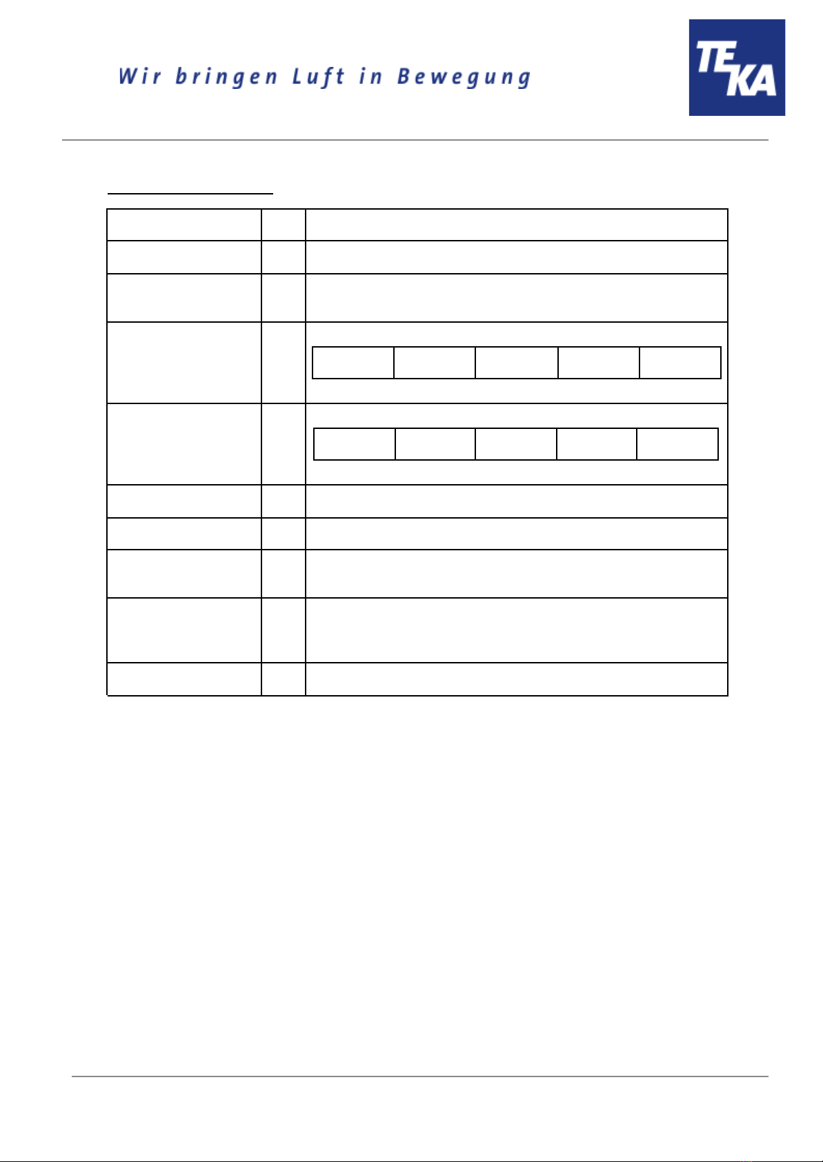
9. Technical data
Supply voltage
V
230 / 400 / 500
Frequency
Hz
50
Type of current
Ph
230 V = 1
400 + 500 V = 3
Engine power
kW
0,75
1,1
1,5
2,2
3,0
Air flow volume max.
m³/h
2000
2500
3000
3500
4000
Protection class
IP54
ISO class
F
Allowed ambient
temperature
°C
+5 to +35 (during operations)
-10 to +40 (during transport and storage)
Max. temperature of
polluted air at the
capture point
°C
+50
Allowed max. humidity
%
70
BA_Sauggebläse_201013_EN
10
12.01.2022
Table of contents
Other Teka Blower manuals


