TEKELEK LoRaWAN User manual

Ultrasonic LoRaWAN
User Manual
www.ime.de
10-09-20

Ultrasonic LoRaWAN User Manual
1 | P a g e
Contents
1. Product Description .................................................................................................................................................................. 2
1.1 Abbreviations/Definitions .......................................................................................................................................... 2
2. Description of Data Transmission ............................................................................................................................................. 3
2.1 Operation Modes....................................................................................................................................................... 3
2.2 Standard Operation ................................................................................................................................................... 3
2.3 Factory Default Operation: ........................................................................................................................................ 3
2.4 Manual Operation...................................................................................................................................................... 3
2.5 Logging Data .............................................................................................................................................................. 3
2.6 Principle of Data Upload ............................................................................................................................................ 3
2.7 Alarm Mode............................................................................................................................................................... 4
2.8 SRC & SRSSI................................................................................................................................................................ 4
3. Configuring Device.................................................................................................................................................................... 5
3.1 LoRaWAN Network Server Response ......................................................................................................................... 5
3.2 Message Types........................................................................................................................................................... 5
3.2.1 Configuration Parameters ................................................................................................................................... 6
3.2.2 Product ID reference ........................................................................................................................................... 6
3.2.3 Measurement...................................................................................................................................................... 7
3.2.4 Status .................................................................................................................................................................. 8
3.2.5 Parameter Read Request..................................................................................................................................... 9
3.2.6 Parameter Read Response ................................................................................................................................ 10
3.2.7 Parameter Write Request.................................................................................................................................. 11
3.2.8 Alarm Notification............................................................................................................................................. 12
3.3 Scheduler................................................................................................................................................................. 14
3.3.1 TX Period (0500)................................................................................................................................................ 14
3.3.2 TX Randomization level (0502).......................................................................................................................... 14
3.3.3 Logging interval (0503)...................................................................................................................................... 14
3.3.4 Status Message TX period (0505) ...................................................................................................................... 15
3.3.5 Ultrasonic “Ping rate” (4005) ............................................................................................................................ 15
3.3.6 Combined Payload message.............................................................................................................................. 15
3.3.7 Static Alarm Threshold Limits............................................................................................................................ 18
3.4 Miscellaneous Parameters ....................................................................................................................................... 19
3.4.1 SRC/SRSSI Filter................................................................................................................................................. 19
3.4.2 Sonic Control..................................................................................................................................................... 20
3.4.3 RF-RSSI Threshold ............................................................................................................................................. 20
4. Technical Specifications .......................................................................................................................................................... 21
4.1 Radio interface......................................................................................................................................................... 21
4.2 External Antenna ..................................................................................................................................................... 21
4.3 Pushbutton switch ................................................................................................................................................... 21
4.4 LED output............................................................................................................................................................... 21
5. On-site maintenance checks................................................................................................................................................... 21
5.1 Mounting ................................................................................................................................................................. 21
5.2 External antenna...................................................................................................................................................... 21
5.2.1 RF antenna ........................................................................................................................................................ 21
5.3 Environment ............................................................................................................................................................ 21
6. Trouble Shooting .................................................................................................................................................................... 22
6.1 LED Radio Signal Strength Flash Code ...................................................................................................................... 22
6.2 LED Error Flash Code................................................................................................................................................ 22
6.3 Manually Testing Sensor .......................................................................................................................................... 22
6.4 Button Press ............................................................................................................................................................ 22
6.5 Dormant Mode ........................................................................................................................................................ 22
7. FAQ:........................................................................................................................................................................................ 23
9-5911-03
www.ime.de
10-09-20
Ultrasonic LoRaWAN User Manual
2 | P a g e
1. Product Description
The Ultrasonic LoRaWAN sensor is a flexible and configurable, battery-operated ultrasonic liquid sensor which is
configured to connect to a LoRaWAN network.
This sensor will measure and report the distance between the device and the surface of the liquid.
The functionality of the sensor includes various alarm triggers, configurable measurement schedule, reporting
schedules & temperature measurement.
Once activated on a LoRaWAN network it will send the measurement data according to its configuration through
the network gateways to the endpoint server accessible by end users.
It may be used for applications such as Liquid level monitoring of fuel, water, waste oil on fixed or portable vessels.
See installation instruction for installation and activation guidelines.
1.1 Abbreviations/Definitions
The following is a list of terms that may be found in this document.
Ullage
The unfilled space between the sensor and the top of the liquid being monitored
RSSI
Received Signal Strength Indicator
SRSSI
Sonic Received Signal Strength Indicator
SRC
Sonic Results Code –a performance metric of the ultrasonic measurement.
Ack
Acknowledgement from the LoRaWAN network server
Message
The data packet / payload / datagram sent across the network
Payload
Data transmitted between sensor and LoRaWAN network
Nibble
Half of a byte
LSB
The Least Significant Bit is the right-most bit in the string
MSB
The Most Significant Bit is the left-most bit in the string
Minor
The right-most bits in the string
Major
The left-most bits in the string
0x
Identifies the number as hexadecimal. e.g. 0x3F Note: numbers are assumed decimal unless specified otherwise.
0b
Identifies the number as binary e.g. 0b1101 Note: numbers are assumed decimal unless specified otherwise.
Unsigned byte
Numbers are only represented in the positive range: 0….256
Signed byte
Will allow numbers to be represented both in the positive and negative ranges: -127 to +127
Waveguide
A waveguide option allows the ultrasonic reading to be measured through a waveguide pipe inserted into the tank to
avoid any obstacles/obstructions that may affect the standard ultrasonic reading
IoT
Internet of Things
Dormant
Dormant units are inactivated and do not make RF transmissions or measurements to ensure the longest battery
service life
www.ime.de
10-09-20

Ultrasonic LoRaWAN User Manual
3 | P a g e
2. Description of Data Transmission
2.1 Operation Modes
Once the sensor has been successfully activated, it will operate in two modes:
A manual connection –By pressing the button
An automatic connection according to the internal connection schedule
2.2 Standard Operation
The Ultrasonic LoRaWAN sensor will remain in low power mode for the majority of its lifetime.
It will briefly wake up and make an ultrasonic measurement of the ullage as per the configuration schedule and
store the result before reverting to low power mode. The sensor will make a predefined number of transmissions
in a time frame defined by the configuration schedule.
2.3 Factory Default Operation:
The following are the factory default settings for the sensor but are configurable.
The sensor will briefly wake up and make an ultrasonic measurement of the ullage every 15 minutes, which is
compared to an alarm limit (if enabled). Every 6 hours the current ultrasonic measurement is stored before
reverting to low power mode. The sensor will make 4 transmissions every 24 hours, one every 6 hours. Every
fourth transmission will expect an acknowledgement from the LoRaWAN server, the other 3 transmissions do not
require this. For data redundancy, each transmission will include one current ultrasonic measurement as part of
the payload as well as last 3 previously uploaded readings. A status message is sent once every 7 days.
2.4 Manual Operation
The sensor can be forced to connect to the LoRaWAN network server at any time by briefly pressing the button for
one second to wake up the sensor. The sensor will take an ultrasonic measurement, connect to the gateway and
transmit a status message which includes a current ultrasonic measurement. During the connection, the dual
colour LED will turn on solid Green, then flash green to indicate that the connection is complete. The sensor will
then revert to low power mode.
2.5 Logging Data
The sensor will store 4 measurements internally which contain the following:
Ullage –Reported in cm
SRC
SRSSI
Internal PCB Temperature in ⁰C
2.6 Principle of Data Upload
The sensor will connect to the LoRaWAN network server for one of the following reasons:
Activation –The user has pressed the button for 1 second to activate the device from dormant mode and
subsequently force a connection to the network.
Manual Connection –The user has pressed the button for 1 second to make a measurement and send a
status message.
Scheduled –The sensor will connect to the LoRaWAN network server according to its schedule.
Regular Status Update –Typically once per week as defined in the schedule.
Alarm –Reporting that alarm limit thresholds have been exceeded (if enabled).
Configuration Update –Soft reset –This occurs in response to a configuration settings update. A hard-
internal reset would also cause a communication.
Note: After a device reset, manual activation or after provisioning, a status message will be uploaded to the
LoRaWAN network server.
www.ime.de
10-09-20
Ultrasonic LoRaWAN User Manual
4 | P a g e
2.7 Alarm Mode
There are up to three separate static alarms levels that can be configured on the sensor. These can be configured
to alarm when the measured value is higher or lower than the defined level.
When a static alarm is activated, an immediate message is sent to the LoRaWAN network server.
This message will indicate which of the static limits was exceeded and will also contain two ultrasonic readings, the
first ultrasonic reading is the one that exceeded the threshold and the second is the previous reading made as
defined by the measurement schedule. In order to avoid false alarms, the ultrasonic measurement reading is tested
against programmable quality metrics SRC: SRSSI filter limits as defined in parameter 0x4004. If the ultrasonic
measurement does not exceed these limits then an alarm is not triggered.
2.8 SRC & SRSSI
In addition to the ullage (represented in CM) there are two additional parameters which can be used to identify the
quality and reliability of an ultrasonic reading.
1. Sonic RSSI: The SRSSI is simply an integer number between 1 (low level) and 10 (expected level) given to the
expected strength of the echo reflected to the transducer. A value of 9 or 10 would normally be expected
from a uniformly flat surface such as from a stable fluid level inside a tank. A low value may indicate that the
sensor is not mounted perpendicular to the surface or that the surface is irregular (not flat) or of a nature
which absorbs ultrasonic signals such as soft furnishings. The SRSSI when used in combination with the SRC is
a useful measure of the overall confidence in the measurement.
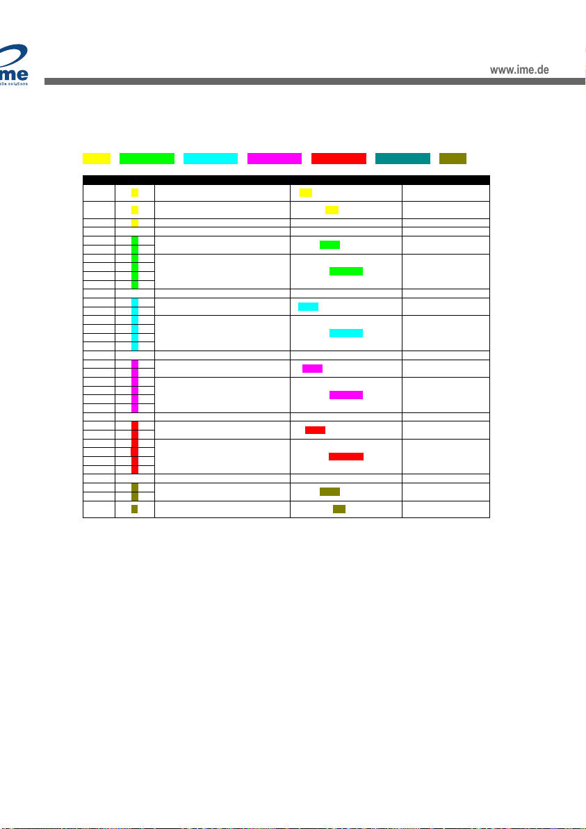
2. Sonic Results Code: The SRC represents the result code of the ultrasonic algorithm which can be used to
deduce whether a reading is likely to be valid or not. An SRC of 9 or 10 are optimal.
Sonic
Result
Code
Range
Near < 80cm
Far >= 80cm
Description
10
Near & Far
Good quality ultrasonic echo.
9
Near
Detected echo indicates operation in ‘blind zone’. i.e. <= 24cms.
8
Near & Far
Best Echo is not the 1st one detected.
7
Near
The first echo was < 25cm but the subsequent echo was stronger so that one was chosen instead.
6
Far
Ullage > 50cm & < 80cm. In this range, Near field algorithm should have reported.
5
Near
Multiple echoes, <= 24 cms.
4
Far
Best Echo > 400cm limit. 1st echo seen is reported.
3
Near
Best Echo > 24cm but a high level of noise
2
Far
Best Echo < 50cms. In this range, Near field algorithm should have reported.
1
Near
1st echo is strongest, but High levels of energy bunched up in the very near field <= 24cms.
0
Near & Far
No echo detected
www.ime.de
10-09-20

Ultrasonic LoRaWAN User Manual
5 | P a g e
3. Configuring Device
3.1 LoRaWAN Network Server Response
Every time a sensor makes an outgoing status connection to the gateway, the LoRaWAN network server has the
option to respond with configuration settings to alter the operation of the device.
Sending responses to the sensor is very useful for tasks such as changing the connection schedule. Care must be
taken, as sending the wrong settings could render the device incapable of correct operation.
3.2 Message Types
The sensor transmits or receives several packet types.
Messages Issued by sensor:
Message Type
Description
Payload Msg.
Type / Port
Measurement:
Sensor sends measurement data to LoRaWAN network server
This is setup periodically when configuring the schedule
0x10
Status:
Sensor sends status data to LoRaWAN network server
This is setup periodically when configuring the schedule
0x30
Parameter Read
Response:
Sensor sends parameter settings to the LoRaWAN network server
0x43
Alarm Notification:
Sensor sends alarm notification to the LoRaWAN network server
0x45
Diagnostic Read
Response:
Sensor sends diagnostics data (mostly ultrasonic) to the LoRaWAN network
server
0x47
Messages issued by LoRaWAN network server:
Message Type
Description
Payload Msg.
Type / Port
Response Ack:
LoRaWAN network server sends a soft “ack” for write request to the LoRaWAN
network sensor
0x40
Parameter Read
Request:
LoRaWAN network server requests the sensor to send parameter settings to the
LoRaWAN network server
0x41
Parameter Write
Request:
Update of parameters on LoRaWAN network sensor
0x42
Diagnostic Read
Request:
LoRaWAN network server requests the sensor to send diagnostic data to the
LoRaWAN network server
0x46
www.ime.de
10-09-20

Ultrasonic LoRaWAN User Manual
6 | P a g e
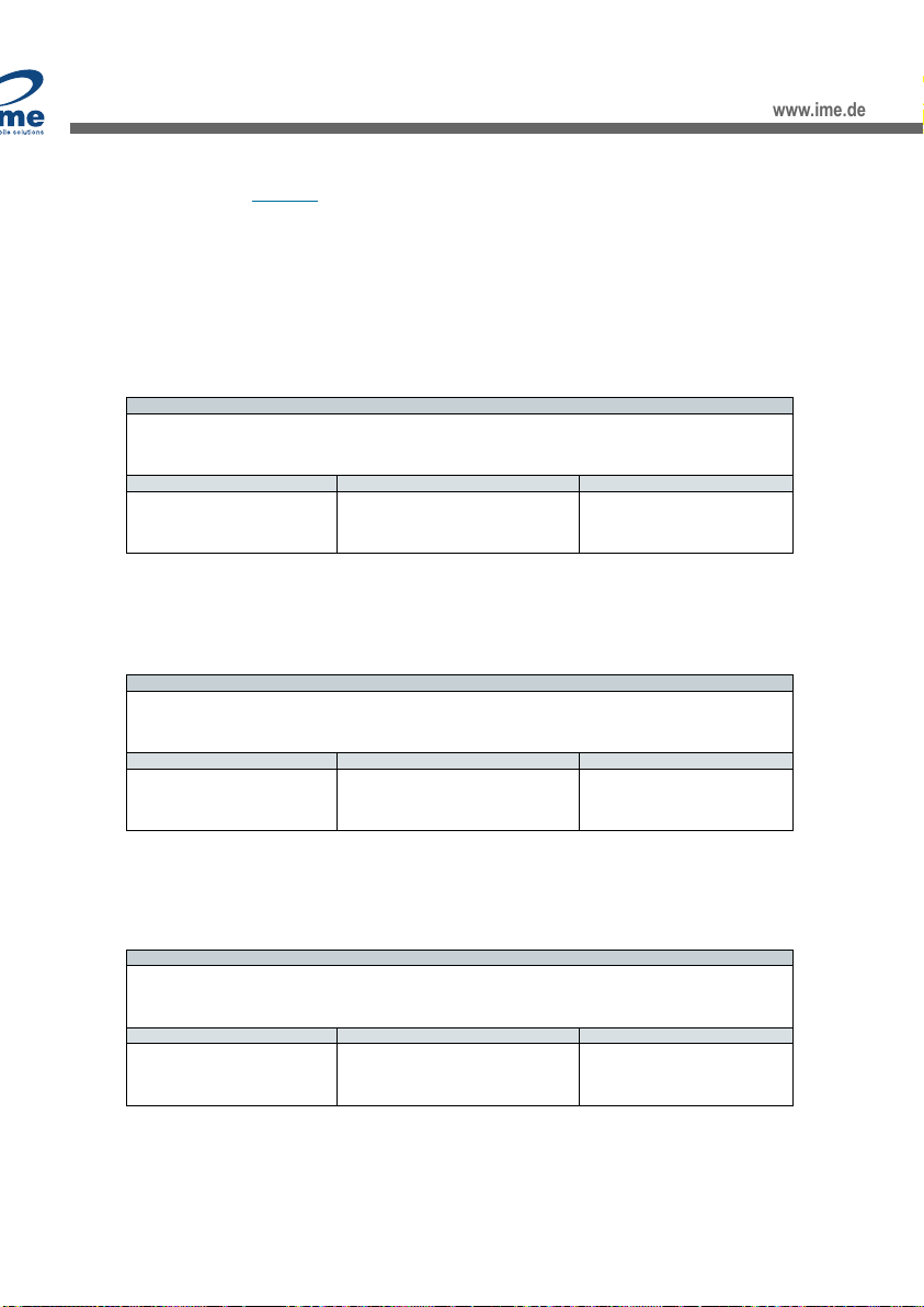
3.2.1 Configuration Parameters
Parameter
0x40
Read/
Write
Parameter
Data
Type
Data
Byte
Length
Default
Value
Description
0x4000
R/W
Sonic Control
u32
4
0x49351928
Characteristic of the Advanced Sonics routine
0x4001
R/W
Static Limit1
u16
2
0
Characteristics of the Limit Alarm (Low/High, Threshold etc)
0x4002
R/W
Static Limit2
u16
2
0
Characteristics of the Limit Alarm (Low/High, Threshold etc)
0x4003
R/W
Static Limit3
u16
2
0
Characteristics of the Limit Alarm (Low/High, Threshold etc)
0x4004
R/W
SRC/SRSSI Filter
u8
1
-
Filters whether a measurement can trigger alarm
0x4005
R/W
Ping Rate
u8
1
15
How often (in minutes) ultrasonic ping/LPG sample occurs
0x4006
R/W
RF_RSSI
Threshold
s8
1
-120
RF RSSI Threshold to generate LED flash response
0x4007
R/W
Control Byte
u8
1
0
Bitwise flags such as bund enable, measurement frame
confirmations
Scheduler
0x05
Read/
Write
Scheduler Parameter
Data
Type
Data
Byte
Length
Default
Value
Units
Description
0x0500
R/W
TX Period
u32
4
86400
seconds
Duration of all transmission windows-
Default 24hours
0x0502
R/W
TX randomisation
period
u32
4
3600
seconds
Duration of one transmission window -
randomisation
0x0503
R/W
Logger Interval
Period
u32
4
21600
seconds
Time between two index measurements -
Default 6hours
0x0505
R/W
Status frame period
u32
4
604800
seconds
Time between two status frame
transmissions - Default 7days
Data Type:
u = unsigned byte, e.g., u32 = unsigned 4 bytes.
s = signed byte
Configurable parameters listing default, minimum and maximum.
PARAMETER:
MINIMUM
MAXIMUM
DEFAULT
UNITS
Scheduler TX Period
1
720
6
Hours
Status TX Period
1
30
7
Days
Logger Interval
2
1440
360
Minutes
TX Randomisation Period
1
240
60
Minutes
Ultrasonic Ping Rate
1
240
15
Minutes
Alarm Static Threshold Limits
22
400
0 (disabled)
cm
Sonic SRC/SRSSI Filter limits
0:0
10:10
9:4
-
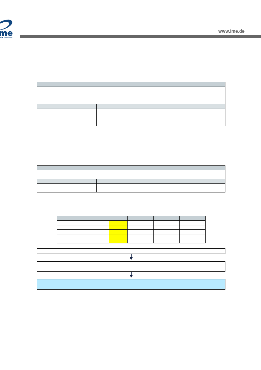
3.2.2 Product ID reference
TEK #
PROD ID field
TEK 766
00
TEK 586
02
TEK 790
03
TEK 733
05
TEK 643
06
TEK 811
07
TEK 822
08
TEK 733A
09
www.ime.de
10-09-20

Ultrasonic LoRaWAN User Manual
7 | P a g e
3.2.3 Measurement
This is a standard message that the sensor sends as scheduled to the LoRaWAN network server.
It includes the latest ultrasonic measurement plus 3 previously sent readings (4 readings in total).
The individual readings comprise of a 2-byte ullage - this represents the distance between the ultrasonic transducer
and the surface of the liquid. From this a calculation of the tank % full can be calculated. The temperature within
the tank is also provided (one byte) and a metric of the quality of the ultrasonic measurement called SRC/ SRSSI (1
Byte) is also provided.
The Alarms byte represents a passive alarm notification (so indicates an alarm if the alarm threshold is set and
exceeded, but the alarm is disabled by default).
Sample Payload: (Payloads are Hexadecimal)
1000000001121B7701131BAA01121BA90114F274
Byte #
Payload
Description
Notes
Results
1
10
Defines the payload type
(See Section 3.2)
0x10 = Measurement
Measurement
2
00
Defines the product identification number
(See Section 3.2.2)
0x00 = TEK 766
TEK 766
3
00
Defines the Alarms
(See Section 3.2.8.1)
0x00 -> 0b00000000
Lim1: Bit0 = 0
Lim2: Bit1 = 0
Lim3: Bit2 = 0
No limits
exceeded
4
00
N/A
N/A
5
01
Defines the ullage reading in cms
(Byte 5 x 28) + Byte 6
(0x01 x 28) + 0x12
(1 x 28) + 18
256 + 18 = 274
274cm
6
12
7
1B
Defines the temperature in °C
- ([256 or 0] - Byte 7)
(See Section 3.2.3.1)
[0x1B = 27 -> 0]
- (0 - 27) = 27
27°C
8
77
SRC: Major nibble of Byte 8
SRSSI: Minor nibble of Byte 8
SRC = 0x7 = 7
SRSSI = 0x7 = 7
SRC=7
SRSSI=7
9
01
Defines the ullage reading in cms
(Byte 9 x 28) + Byte 10
(0x01 x 28) + 0x13
(1 x 28) + 19
256 + 19 = 275
275cm
10
13
11
1B
Defines the temperature in °C
- ([256 or 0] - Byte 11)
(See Section 3.2.3.1)
[0x1B = 27 -> 0]
- (0 - 27) = 27
27°C
12
AA
SRC: Major nibble of Byte 12
SRSSI: Minor nibble of Byte 12
SRC = 0xA = 10
SRSSI = 0xA = 10
SRC=10
SRSSI=10
13
01
Defines the ullage reading in cms
(Byte 13 x 28) + Byte 14
(0x01 x 28) + 0x12
(1 x 28) + 18
256 + 18 = 274
274cm
14
12
15
1B
Defines the temperature in °C
- ([256 or 0] - Byte 15)
(See Section 3.2.3.1)
[0x1B = 27 -> 0]
- (0 - 27) = 27
27°C
16
A9
SRC: Major nibble of Byte 16
SRSSI: Minor nibble of Byte 16
SRC = 0xA = 10
SRSSI = 0x9 = 9
SRC=10
SRSSI=9
17
01
Defines the ullage reading in cms
(Byte 17 x 28) + Byte 18
(0x01 x 28) + 0x14
(1 x 28) + 20
256 + 20 = 276
276cm
18
14
19
F2
Defines the temperature in °C
- ([256 or 0] - Byte 19)
(See Section 3.2.3.1)
[0xF2 = 242 -> 256]
- (256 - 242) = -14
-14°C
20
74
SRC: Major nibble of Byte 20
SRSSI: Minor nibble of Byte 20
SRC = 0x7 = 7
SRSSI = 0x4 = 4
SRC=7
SRSSI=4
3.2.3.1 Temperature
Temperature ranges -20°C to +50°C (Variable range -127 -> 127)
- ([256 or 0] - Byte)
If the decimal conversion of the byte is greater than 32 then the number required for the formula is 256
otherwise the number required for the formula is 0.
www.ime.de
10-09-20
Ultrasonic LoRaWAN User Manual
8 | P a g e
3.2.4 Status
This is a packet that the sensor sends as scheduled to the LoRaWAN network server.
It is also generated by pressing the button on the sensor.
Sample Payload: (Payloads are Hexadecimal)
300000010106360063006300040600181BAA
Byte #
Payload
Description
Notes
Results
1
30
Defines the payload type
(See Section 3.2)
0x30 = Status
Status
2
00
Defines the product identification number
(See Section 3.2.2)
0x00 = TEK 766
TEK 766
3
00
N/A
N/A
4
01
Defines the Hardware ID
0x01 = 1
1
5
01
Defines the firmware revision
Byte 5 . Byte 6
0x01 . 0x06 = 1.6
1.6
6
06
7
36
Defines the reason for the last reset
(See Section 3.2.5.1)
0x36 = 0b00110110
Contact: Bit0,Bit1 = 0b10 = 2
Reset: Bit2,Bit3,Bit4 = 0b101 = 5
Active: Bit5 = 0b1 = 1
Manual Contact
System Request Reset
Active
8
00
N/A
N/A
9
63
Defines the sensor RSSI
- Byte 9
- 0x63 = - 99
-99dBm
10
00
N/A
N/A
11
63
Defines the remaining battery %
0x63 = 99
99%
12
00
Defines the measurement Sections in minutes
(Byte 12 x 28) + Byte 13
(0x00 x 28) + 0x04
(0 x 256) + 4 = 4
4 mins
13
04
14
06
Defines the schedule transmit period in hours
0x06 = 6
6 Hours
15
00
Defines the ullage reading in cms
(Byte 15 x 28) + Byte 16
(0x00 x 28) + 0x18
0 + 24 = 24
24cm
16
18
17
1B
Defines the temperature in °C
- ([256 or 0] - Byte 17)
(See Section 3.2.3.1)
[0x1B = 27 -> 0]
- (0 - 27) = 27
27°C
18
AA
SRC: Major nibble of Byte 18
SRSSI: Minor nibble of Byte 18
SRC = 0xA = 10
SRSSI = 0xA = 10
SRC=10
SRSSI=10
The status frame contains some important information, but information which would rarely change and is not
required to be transmitted on a daily basis.
Typically, the Status frame will be transmitted once per week and contains information such as the sensor
Firmware version, the current Battery level as well as a single ultrasonic measurement (which is useful if the status
frame is uploaded during an installation/diagnostic button press). The sensor RSSI is the signal strength of the unit
received by the gateway.
Note: The scheduled TX period is limited to a single byte and so is limited to representing a maximum of 255 hours.
www.ime.de
10-09-20

Ultrasonic LoRaWAN User Manual
9 | P a g e
3.2.4.1 Status Byte
The status byte is contained in the status frame (which is typically sent once per week). It contains information
about the connection reason (i.e. was it via a button press or a scheduled connection). Also, if the connection
reason was due to a "reset", then the corresponding "LastResetReason" can be extracted.
Bit7
Bit6
Bit5
Bit4
Bit3
Bit2
Bit1
Bit0
Reserved
Reserved
Active Status
LastResetReason:
0 = Power on reset
1 = Brown out reset
2 = External reset
3 = Watchdog reset
4 = Cortex-M3 lockup reset
5 = Cortex-M3 system request reset
6 = EM4 reset
7 = System has been in Backup mode
Contact Reason
0 = Reset
1 = Scheduled
2 = Manual
3 = Activation
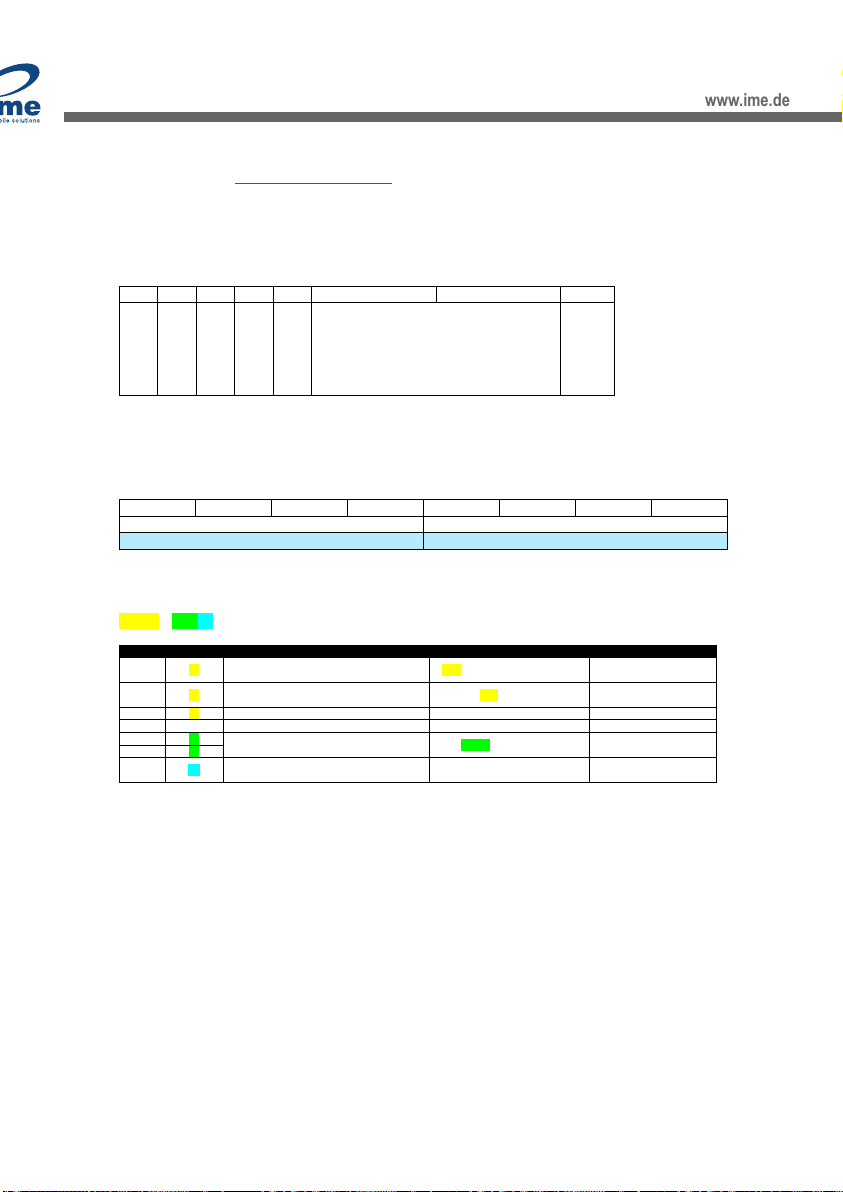
3.2.5 Parameter Read Request
This is a message issued by the LoRaWAN network server requesting information on current parameter settings of
the sensor. This can contain several parameter requests linked together but is limited to a maximum combined size
of 45 bytes.
(See Section 3.2.1 for parameters table)
Sample Payload: (Payloads are Hexadecimal)
41000040014002
Byte #
Payload
Description
Notes
Results
1
41
Defines the payload type
(See Section 3.2)
0x41 = Parameter Read Request
Parameter Read Request
2
00
Defines the product identification number
(See Section 3.2.2)
0x00 = TEK 766
TEK 766
3
00
N/A
N/A
4
40
Defines the Parameter ID
(See Section 3.2.1)
0x4001 = Static Limit1
Static Limit 1
5
01
6
40
Defines the Parameter ID
(See Section 3.2.1)
0x4002 = Static Limit 2
Static Limit 2
7
02
This can contain several parameter requests concatenated together, though care must be taken not to request
settings which combined size would exceed 45 bytes.
www.ime.de
10-09-20
Ultrasonic LoRaWAN User Manual
10 | P a g e
3.2.6 Parameter Read Response
This is a message that the sensor sends in response to the LoRaWAN network server requesting the
aforementioned Parameter Read Request.
(See Section 3.2.1 for parameters table)
Sample Payload: (Payloads are Hexadecimal)
43000002400164480240011600
Byte #
Payload
Description
Notes
Results
1
43
Defines the payload type
(See Section 3.2)
0x43 = Parameter Read Response
Parameter Read Response
2
00
Defines the product identification
number
(See Section 3.2.2)
0x00 = TEK 766
TEK 766
3
00
N/A
N/A
4
02
Data length after parameters
0x02
02
5
40
Defines the Parameter ID
(See Section 3.2.1)
0x4001 = Static Limit1
Static Limit 1
6
01
7
64
Defines the static threshold limits
(See Section 3.3.7)
LSB First = 0x4864
Threshold = 100cm
Tolerance = 2cm
Alarm = Enabled
Polarity = Lower than Threshold
8
48
9
02
Data length after parameters
0x02
02
10
40
Defines the Parameter ID
(See Section 3.2.1)
0x4001 = Static Limit1
Static Limit 1
11
01
12
16
Defines the static threshold limits
(See Section 3.3.7)
LSB First = 0x0016
Threshold = 22cm
Tolerance = 0cm
Alarm = Not Enabled
Polarity = Lower than Threshold
13
00
A response frame to read parameters response largely resembles a write parameter request i.e. the message
contains a setting length field (as different parameters are of different length) as well as the Category, ID and
corresponding parameter value.
Please note the byte order of multi-byte parameter responses are LSB first. i.e. a value of 20 in a 4-byte parameter
is represented as 0x14000000
Note: All ‘parameter read responses’ are ‘confirmed’ packets that is, the sensor will make three attempts to send
the data. If unsuccessful, the Application server will have to make another attempt by sending a new ‘parameter
read request’. For sensors in areas with weak signal strength – it is recommended to send shorter parameter
requests.
3.2.6.1 Response code Byte
This byte is sent in response to a LoRaWAN downlink frame (i.e. to change a parameter). In normal circumstances,
a response code of 0 is expected to be returned, indicating the downlink action was a success.
Bit7
Bit6
Bit5
Bit4
Bit3
Bit2
Bit1
Bit0
Reserved
Reserved
Reserved
Reserved
Reserved
Reserved
Reserved
Response Code
0 = Write Request successfully received
1 = Write request/read request failed.
2 = Write command not recognized.
www.ime.de
10-09-20

Ultrasonic LoRaWAN User Manual
11 | P a g e
3.2.7 Parameter Write Request
This is a message issued by the LoRaWAN network server to request a change to the parameter settings on the
LoRaWAN network sensor.
The data representing the parameter settings may be of variable length as multiple parameters can be sent
simultaneously and each parameter is also of variable length.
(See Section 3.2.1 for parameters table)
Sample Payload: (Payloads are Hexadecimal)
420000040505803A0900
Byte #
Payload
Description
Notes
Results
1
42
Defines the payload type
(See Section 3.2)
0x42 = Parameter Write Request
Parameter Write Request
2
00
Defines the product identification number
(See Section 3.2.2)
0x00 = TEK 766
TEK 766
3
00
N/A
N/A
4
04
Data length after parameters
0x04
04
5
05
Defines the Parameter ID
(See Section 3.2.1)
0x0505 = Status frame period
Status frame period
6
05
7
80
Defines the Parameter Write Request
Combination of Byte 7 to Byte 10
(See Section 3.3)
0x803A0900
7 Days
8
3A
9
09
10
00
The data representing the S parameters may be of variable length
This is because multiple parameters can be sent simultaneously, and each parameter is of variable length (as
indicated by the Data Length field)
Note: The byte order of multi-byte parameter responses are LSB first i.e. a value of 20 in a 4-byte parameter is
represented as 0x14000000.
www.ime.de
10-09-20

Ultrasonic LoRaWAN User Manual
12 | P a g e
3.2.8 Alarm Notification
This is a packet that the sensor sends to the LoRaWAN network server if a valid ultrasonic reading exceeds an alarm
threshold.
This packet will indicate which of the static limits was exceeded and will also provide two ultrasonic readings.
The first is the reading that exceeded the threshold and the second is the reading logged previously to that.
The alarms are structured similarly to a standard measurement apart from the different message type and that
only two readings are sent.
Sample Payload: (Payloads are Hexadecimal)
45000100001E17AA001E16A9
Byte #
Payload
Description
Notes
Results
1
45
Defines the payload type
(See Section 3.2)
0x45 = Alarm Notification
Alarm Notification
2
00
Defines the product identification number
(See Section 3.2.2)
0x00 = TEK 766
TEK 766
3
01
Defines the reason for Alarm
(See Section 3.2.7.1)
0x01 = 0b00000001
Lim1: Bit0 = 1
Lim2: Bit1 = 0
Lim3: Bit2 = 0
Static Limit 1 Exceeded
4
00
N/A
N/A
5
00
Defines the ullage reading in cms
(Byte 5 x 28) + Byte 6
(0x00 x 28) + 0x1E
(0 x 28) + 30
0 + 30 = 30
30cm
6
1E
7
17
Defines the temperature in °C
- ([256 or 0] - Byte 7)
(See Section 3.2.3.1)
[0x17 = 23 -> 0]
- (0 - 23) = 23
23°C
8
AA
SRC: Major nibble of Byte 8
SRSSI: Minor nibble of Byte 8
SRC = 0xA -> 10
SRSSI = 0xA -> 10
SRC=10
SRSSI=10
9
00
Defines the ullage reading in cms
(Byte 9 x 28) + Byte 10
(0x00 x 28) + 0x1E
(0 x 28) + 30
0 + 30 = 30
30cm
10
1E
11
16
Defines the temperature in °C
- ([256 or 0] - Byte 7)
(See Section 3.2.3.1)
[0x16 = 22 -> 0]
- (0 - 22) = 22
22°C
12
A9
SRC: Major nibble of Byte 12
SRSSI: Minor nibble of Byte 12
SRC = 0xA -> 10
SRSSI = 0x9 -> 9
SRC=10
SRSSI=9
The alarms frame is structurally similar to a standard measurement frame apart from the different message type
(to indicate an immediate alarm notification as opposed to a scheduled measurement) and that only two readings
are sent (the "alarming" reading, plus the previously logged reading).
www.ime.de
10-09-20

Ultrasonic LoRaWAN User Manual
13 | P a g e
3.2.8.1 Alarm byte
Bit7
Bit6
Bit5
Bit4
Bit3
Bit2
Bit1
Bit0
Reserved
Reserved
Reserved
Reserved
Bund Alarm
Limit 3
Limit 2
Limit 1
Limit 1: Flag is set if most recently measured reading exceeds the "Limit" threshold parameters. The flag is
cleared if the reading + hysteresis falls back below the threshold.
Bund Alarm: Not implemented.
3.2.8.2 Alarms
Each sensor has three static limit alarms that are programmed in centimetres.
An alarm is generated when a valid ultrasonic measurement is recorded that exceeds the static alarm threshold
limits.
There is also a polarity flag which can set the direction of the alarm threshold so that an alarm is generated if the
ullage is less or greater than these values.
A hysteresis level limit of between 0 and 15cm is allowed. The minimum threshold level alarm allowable is set to
22cm for operational reasons.
A valid ultrasonic measurement is used to test against the static alarm limits. This requires that the ultrasonic
reading must exceed the SRC & SRSSI filter to be considered a valid reading. The default values are {9:4} and it is
not recommended to change these without guidance from application support.
Once an alarm is generated, it is sent from the sensor and it requires a LoRaWAN network server response over the
LoRaWAN network.
The sensor will make three attempts to send an alarm packet if an acknowledgment is not received, if it does not
receive an acknowledgment then no further attempts will be made.
A new alarm will only be generated once the existing alarm condition has been cleared.
The device alarms are deactivated as default but may be enabled through a configuration change.
www.ime.de
10-09-20
Ultrasonic LoRaWAN User Manual
14 | P a g e
3.3 Scheduler
The sensor will upload data at regular intervals. These intervals are defined by the scheduler which sets up the
ultrasonic measurements, logging intervals and RF transmission rates.
The scheduler defines the following key parameters: (See Section 3.2.1 for default, maximum and minimum
values).
3.3.1 TX Period (0500)
The TX period is the time between packet transmissions to the LoRaWAN network server, measured in hours.
Increasing the frequency of radio transmissions reduces the battery lifetime.
The formula for creating the payload structure for this is as follows:
Formula
1. Hours x 60 x 60 = Value in Seconds
2. Convert decimal to hexadecimal (Values) = ’XXYYZZ’
3. Switch Byte Endianness.
4. Pad Word to Bytes length as per 3.2.1 with zeros.
Default (6 Hours)
Maximum (720 Hours)
Minimum (1 Hour)
1. 6 x 60 x 60 = 21600 Seconds
2. 21600 = 0x5460
3. = 6054
4. Payload = 60540000 [u32]
1. 720 x 60 x 60 = 2592000 Seconds
2. 2592000 = 0x278D00
3. = 008D27
4. Payload = 008D2700
1. 1 x 60 x 60 = 3600 Seconds
2. 3600 = 0x0E10
3. = 100E
4. Payload = 100E0000
3.3.2 TX Randomization level (0502)
The TX randomization is an additional time interval of random length centred around the TX Period transmission,
measured in minutes. The range allowed is from 1 minute to ¼ of the TX period.
The formula for creating the payload structure for this is as follows:
Formula
1. Minutes x 60 = Value in Seconds
2. Convert decimal to hexadecimal (Values) = ’XXYY’
3. Switch Byte Endianness.
4. Pad Word to Bytes length as per 3.2.1 with zeros
Default (60 Minutes)
Maximum (240 Minutes)
Minimum (1 Minute)
1. 60 x 60 = 3600 Seconds
2. 3600 = 0x0E10
3. = 100E
4. Payload = 100E0000
1. 240 x 60 = 14400 Seconds
2. 14400 = 0x3840
3. = 4038
4. Payload = 40380000
1. 1x 60 = 60 Seconds
2. = 0x3C
3. = 3C
4. Payload = 3C000000
3.3.3 Logging interval (0503)
The Logging interval is the time period during which 4 ultrasonic measurements are made. It should be equal to or
greater than the ‘ping rate’ and evenly divide into the TX period. By default, it’s normally set equal to the TX Period.
The formula for creating the payload structure for this is as follows:
Formula
1. Minutes x 60 = Value in Seconds
2. Convert decimal to hexadecimal (Values) = ’XXYYZZ’
3. Switch Byte Endianness.
4. Pad Word to Bytes length as per 3.2.1 with zeros
Default (360 Minutes)
Maximum (1440 Minutes)
Minimum (2 Minute)
1. 360 x 60 = 21600 Seconds
2. 21600 = 0x5460
3. = 6054
4. Payload = 60540000
1. 1440 x 60 = 86400 Seconds
2. 86400 = 0x015180
3. = 805101
4. Payload = 80510100
1. 2 x 60 = 120 Seconds
2. 120 = 0x78
3. = 78
4. Payload = 78000000
www.ime.de
10-09-20
Ultrasonic LoRaWAN User Manual
15 | P a g e
3.3.4 Status Message TX period (0505)
The Status message TX period is the time between each status packet radio transmission, measured in days. The
status period should be set to a minimum of twice the scheduler TX period for correct operation.
The formula for creating the payload structure for this is as follows:
Formula
1. Days x 24 x 60 x 60 = Value in Seconds
2. Convert decimal to hexadecimal (Values) = ’XXYYZZ’
3. Switch Byte Endianness.
4. Pad Word to Bytes length as per 3.2.1 with zeros
Default (7 Days)
Maximum (30 Days)
Minimum (1 Day)
1. 7 x 24 x 60 x 60 = 604800 Secs
2. 604800 = 0x093A80
3. = 803A09
4. Payload = 803A0900
1. 30 x 24 x 60 x 60 = 2592000 Secs
2. 2592000 = 0x278D00
3. = 008D27
4. Payload = 008D2700
1. 1 x 24 x 60 x 60 = 86400 Secs
2. 86400 = 0x015180
3. = 805101
4. Payload = 80510100
3.3.5 Ultrasonic “Ping rate” (4005)
The Ultrasonic “Ping rate” is how often an ultrasonic measurement is taken, measured in minutes. A faster ping
rate allows for a more responsive performance when the alarm functionality is enabled, but at a cost of reduced
battery life.
The formula for creating the payload structure for this is as follows:
Formula
1. Convert decimal to hexadecimal (Values) = ’XX’
2. Pad Word to Bytes length as per 3.2.1
Default (15 Minutes)
Maximum (240 Minutes)
Minimum (1 Minute)
5. 15 = 0x0F
6. Payload = 0F
5. 240 = 0xF0
6. Payload = F0
5. 1 = 0x01
6. Payload = 01
3.3.6 Combined Payload message
3.3.6.1 Default Schedule
Parameter
Schedule
Measurement
Values (DEC)
Payload (HEX)
TX Period (0500)
6
hours
21600
60540000
TX Randomization level (0502)
60
mins
3600
100E0000
Logging interval (0503)
360
mins
21600
60540000
Status message TX period (0505)
7
days
604800
803A0900
Ultrasonic "Ping rate"(4005)
15
mins
15
0F
"Payload Message Type” & "Data Length" & Parameter & Payload
"420000" & "04" & 0500 & 60540000 & "04" & 0502 & 100E0000 & "04" & 0503 & 60540000 & "04" & 0505 &
803A0900 & "04" & 0507 & 80510100 & "01"& 4005 & 0F
Payload:
4200000405006054000004502100E000004050360540000040505803A0900040507805101000140050F
www.ime.de
10-09-20

Ultrasonic LoRaWAN User Manual
16 | P a g e
3.3.6.2 Custom Schedules
Parameter
Schedule
Measurement
Values (DEC)
Payload (HEX)
TX Period (0500)
1
hours
3600
100E0000
TX Randomization level (0502)
5
mins
300
2C010000
Logging interval (0503)
60
mins
3600
100E0000
Status message TX period (0505)
1
days
86400
80510100
Ultrasonic "Ping rate"(4005)
15
mins
15
0F
Payload:
420000040500100E00000405022C010000040503100E000004050580510100040507805101000140050F
Parameter
Schedule
Measurement
Values (DEC)
Payload (HEX)
TX Period (0500)
3
hours
10800
302A0000
TX Randomization level (0502)
15
mins
900
84030000
Logging interval (0503)
180
mins
10800
302A0000
Status message TX period (0505)
7
days
604800
803A0900
Ultrasonic "Ping rate"(4005)
15
mins
15
0F
Payload:
420000040500302A000004050284030000040503302A0000040505803A0900040507805101000140050F
Parameter
Schedule
Measurement
Values (DEC)
Payload (HEX)
TX Period (0500)
12
hours
43200
C0A80000
TX Randomization level (0502)
30
mins
1800
08070000
Logging interval (0503)
720
mins
43200
C0A80000
Status message TX period (0505)
7
days
604800
803A0900
Ultrasonic "Ping rate"(4005)
15
mins
15
0F
Payload:
420000040500C0A8000004050208070000040503C0A80000040505803A0900040507805101000140050F
Parameter
Schedule
Measurement
Values (DEC)
Payload (HEX)
TX Period (0500)
24
hours
86400
80510100
TX Randomization level (0502)
60
mins
3600
100E0000
Logging interval (0503)
1440
mins
86400
80510100
Status message TX period (0505)
7
days
604800
803A0900
Ultrasonic "Ping rate"(4005)
15
mins
15
0F
Payload:
42000004050080510100040502100E000004050380510100040505803A0900040507805101000140050F
Parameter
Schedule
Measurement
Values (DEC)
Payload (HEX)
TX Period (0500)
168
hours
604800
803A0900
TX Randomization level (0502)
240
mins
14400
40380000
Logging interval (0503)
1440
mins
86400
80510100
Status message TX period (0505)
14
days
1209600
00751200
Ultrasonic "Ping rate"(4005)
15
mins
15
0F
Payload:
420000040500803A0900040502403800000405038051010004050500751200040507805101000140050F
Note: It is possible, due to the flexibility of the scheduler, to use parameter values that might give
unexpected behaviour –for example if the Logging interval or TX randomisation is longer than
recommended values. For this reason, it is preferred to use the above profiles.
It is only possible to change a sensor configuration when the sensor wakes up to perform measurement and
transmits to the LoRaWAN network or manually by pressing the sensor button.
www.ime.de
10-09-20
Ultrasonic LoRaWAN User Manual
17 | P a g e
(See Section 3.2.1 for parameters table)
Sample Payload (Default Schedule): (Payloads are Hexadecimal)
42000004050060540000040502100E000004050360540000040505803A0900040507805101000140050F
Byte #
Payload
Description
Notes
Results
1
42
Defines the payload type
(See Section 3.2)
0x42 = Parameter Write Response
Parameter Write Response
2
00
Defines the product identification number
(See Section 3.2.2)
0x00 = TEK 766
TEK 766
3
00
N/A
N/A
4
04
Data length after parameters
0x04
04
5
05
Defines the Parameter ID
(See Section 3.2.1)
0x0500 = TX Period
TX Period
6
00
7
60
Defines the Parameter Write Request
Combination of Byte 7 to Byte 10
(See Section 3.3.1)
0x60540000
6 Hours Daily
8
54
9
00
10
00
11
04
Data length after parameters
0x04
04
12
05
Defines the Parameter ID
(See Section 3.2.1)
0x0502 = TX Randomisation Period
TX Randomisation Period
13
02
14
10
Defines the Parameter Write Request
Combination of Byte 14 to Byte 17
(See Section 3.3.2)
0x100E0000
60 Minutes
15
0E
16
00
17
00
18
04
Data length after parameters
0x04
04
19
05
Defines the Parameter ID
(See Section 3.2.1)
0x0503 = Logger Interval Period
Logger Interval Period
20
03
21
60
Defines the Parameter Write Request
Combination of Byte 21 to Byte 24
(See Section 3.3.3)
0x60540000
360 Minutes
22
54
23
00
24
00
25
04
Data length after parameters
0x04
04
26
05
Defines the Parameter ID
(See Section 3.2.1)
0x0505 = Status Frame Period
Status Frame Period
27
05
28
80
Defines the Parameter Write Request
Combination of Byte 28 to Byte 31
(See Section 3.3.4)
0x803A0900
7 Days
29
3A
30
09
31
00
39
01
Data length after parameters
0x01
01
40
40
Defines the Parameter ID
(See Section 3.2.1)
0x4005 = Ping Rate
Ping Rate
41
05
45
0F
Defines the Parameter Write Response
(See Section 3.3.5)
0x0F = 15
15 Minutes
www.ime.de
10-09-20

Ultrasonic LoRaWAN User Manual
18 | P a g e
3.3.7 Static Alarm Threshold Limits
Each sensor can have up to three static alarms, so depending on the polarity an alarm is generated if the ullage is
greater, or less than these values. The alarm threshold must be 22cm or greater. The device has 2cm of in-built
hysteresis.
Description
Notes
Example
Limit Polarity Flag:
1=Reading Higher than Threshold, 0=Lower.
0
Enable alarm:
1=Enabled, 0=Disable (Alarm Status flags will be set, irrespectively)
1
Hysteresis: cm
The "tolerance" to be exceeded before clearing alarm (15cm max)
2
Threshold: cm
The threshold for level alarm
100
lim n (hex) =
4864
Formula:
1. Threshold + (Tolerance x 2^10) + (Alarm: 1=Enabled, 0=Disabled x 2^14) + (Polarity: 1=Higher, 0=Lower x 2^15) = Result
2. Convert the result to HEX
Example:
100 + (2 x 1024) + (1x 16384) + (0x 32768)
100 + 2048 + 16384 + 0
18532 = 0x4864
(See Section 3.2.1 for parameters table)
Sample Payload (All alarms): (Payloads are Hexadecimal)
420000024001644802400216000240031600
Byte #
Payload
Description
Notes
Results
1
42
Defines the payload type
(See Section 3.2)
0x42 = Parameter Write Response
Parameter Write Response
2
00
Defines the product identification number
(See Section 3.2.2)
0x00 = TEK 766
TEK 766
3
00
N/A
N/A
4
02
Data length after parameters
0x02
02
5
40
Defines the Parameter ID
(See Section 3.2.1)
0x4001 = Static Limit 1
Static Limit 1
6
01
7
64
Defines the Parameter Write Response
(See Section 3.3.7)
0x6448
Lower than Threshold
Alarm Enabled
Tolerance = 2cm
Threshold = 100cm
8
48
9
02
Data length after parameters
0x02
02
10
40
Defines the Parameter ID
(See Section 3.2.1)
0x4002 = Static Limit 2
Static Limit 2
11
02
12
16
Defines the Parameter Write Response
(See Section 3.3.7)
0x1600
Lower than Threshold
Alarm Not Enabled
Tolerance = 0cm
Threshold = 22cm
13
00
14
02
Data length after parameters
0x02
02
15
40
Defines the Parameter ID
(See Section 3.2.1)
0x4003 = Static Limit 3
Static Limit 3
16
03
17
16
Defines the Parameter Write Response
(See Section 3.3.7)
0x1600
Lower than Threshold
Alarm Not Enabled
Tolerance = 0cm
Threshold = 22cm
18
00
www.ime.de
10-09-20
Ultrasonic LoRaWAN User Manual
19 | P a g e
3.4 Miscellaneous Parameters
Configuration bytes for miscellaneous parameters allow for setting of confirmation messages.
Bit 1 & 2 of the Configuration flags set the ‘Measurement Frame Confirmation’ –this is how frequently
measurement messages are ‘confirmed’ or acknowledged by the LoRaWAN network server. (The parameter
0x4007 allows the user to write the appropriate value.)
There is a network cost of sending acknowledgment packets to sensors hence there are four options allowed:
Bit7
Bit6
Bit5
Bit4
Bit3
Bit2
Bit1
Bit0
Reserved
Reserved
Reserved
Reserved
Reserved
Measurement Frame Confirmations
0 = No confirmed transmissions - ACK is OFF
1= Confirm every transmission
2 = Confirm every 4th transmission
3 = Confirm every 8th transmission
Bund
Enable
3.4.1 SRC/SRSSI Filter
This byte is divided into two nibbles. The Ultrasonic Sonic Result Code/Sonic RSSI values must exceed this filter
before any limit alarm testing occurs.
Bit7
Bit6
Bit5
Bit4
Bit3
Bit2
Bit1
Bit0
SRC Filter: 0 - A (Hex)
SRSSI Filter: 0 - A (Hex)
A
A
(See Section 3.2.1 for parameters table)
Sample Command: (Payloads are Hexadecimal)
420000014004AA
Byte #
Payload
Description
Notes
Results
1
42
Defines the payload type
(See Section 3.2)
0x42 = Parameter Write Response
Parameter Write Response
2
00
Defines the product identification number
(See Section 3.2.2)
0x00 = TEK 766
TEK 766
3
00
N/A
N/A
4
01
Data length after parameters
0x01
01
5
40
Defines the Parameter ID
(See Section 3.2.1)
0x4004 = SRC/RSSI Filter
SRC/RSSI Filter
6
04
7
AA
SRC: Major nibble of Byte 7
SRSSI: Minor nibble of Byte 7
SRC = 0xA -> 10
SRSSI = 0xA -> 10
SRC=10
SRSSI=10
www.ime.de
10-09-20
Other manuals for LoRaWAN
1
Table of contents
Other TEKELEK Accessories manuals


