TEKELEK Ultrasonic LoRaWAN User manual

Ultrasonic LoRaWAN
Installation Guide (US 915mhz)
Thank you for purchasing the Tekelek Ultrasonic LoRaWAN sensor which
uses ultrasonic technology to measure the liquid level of your tank and
then communicates this data to a LoRaWAN network.
STEP 1: Activation
The Ultrasonic LoRaWAN sensor works in conjunction with a LoRaWAN
network and a connected platform and before activation must first be
registered with both. Access to the LoRaWAN backend server is required
to verify that the unit has correctly joined the network. See User Manual
for further details.
Ensure that the LoRaWAN™network is within communication range of the
sensor. This should occur before the sensor is physically fitted onto the
Tank. The sensor supports one factory configurable sub-band between 1
and 8.
Place the sensor as close as possible to the point of installation, press the
button for 1 second to connect to the LoRaWAN network and upload a
status message.
•The LED will stay illuminated as the sensor registers:
−Red LED flashing = The sensor is registering & connecting for the first
time. (Sensor is shipped in dormant state).
−Green LED flashing = The sensor is already registered. The
connection process will take between 20 & 40 seconds.
•After the connection has completed, the LED will
flash on & off (to indicate whether the connection
was a success or failure).
1
LED Patterns
•Press and hold the button for approximately 1 second, until the LED
turns green.
•Wait approximately 10-20 seconds and observe if the LED flashes
green or red.
See the following for description of Green/Red LED flash codes.
LED Radio Signal Strength Flash Codes:
LED Pattern
Function
Green X 3 Flashes
Excellent signal strength
Green X 2 Flashes
Good signal strength
Green X 1 Flash
Adequate signal strength
Alternate Green/Red Flash
Weak signal strength
Weak signal strength: Try 5 times and if this response is stable then
it’s deemed adequate. If the sensor shows some double red flashes
during this signal strength test - Sensor may need to be elevated for
best performance.
LED Error Flash Codes:
LED
Pattern
Function
Red X 1
Flash
Device registered with an incorrect AppKey.
Red X 2
Flashes
No response from LoRaWAN network
Red X 3
Flashes
General Error. Please try again. If the error
persists, contact the supplier for support.
2
STEP 2: Installation
The following outlines the Ultrasonic LoRaWAN sensor mounting options.
•The sensor must sit in a vertical position on top of the tank and be
fitted such that the sensor has a clear path to the tank contents.
Position it so that there are no internal obstructions that may
interfere with the ultrasonic signal.
•If obstacles cannot be avoided, then a waveguide may be required.
Please refer to Appendix 1 for further details.
•Locate a suitably positioned threaded opening on the top of the tank
to hold the sensor.
−The sensor will fit directly into threaded 2” BSP (British Standard
Pipe) existing tank connections.
−Ensure that the rubber seal is placed, and that the sensor is screwed
correctly into the tank. Do not over-tighten!
•For tanks that do not contain a suitably positioned threaded opening
on the top of the tank to hold the sensor, please refer to Appendix 2
& 5.
3
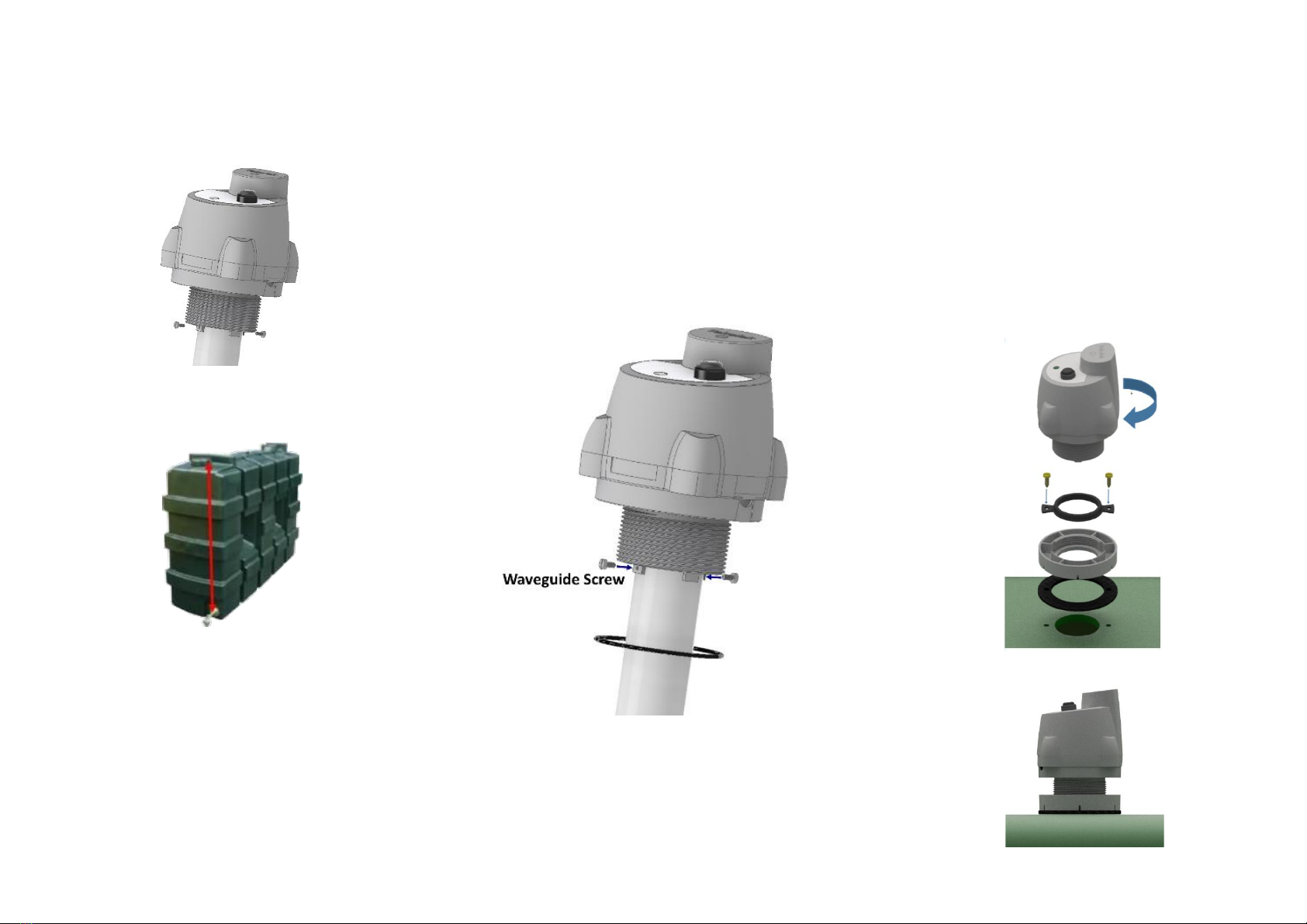
Appendix 1: Standard Waveguide
•For the waveguide option, source a suitable pipe to act as the
waveguide. This pipe should have an outer diameter of 40mm. The
recommended pipe material is PVC (domestic waste pipe is often
used). Other materials are possible but should be checked for
chemical resistance to fuel oil.
•The pipe should be cleanly cut to length. The length required should
be measured from the top of the tank (where the sensor is to be
mounted) to that of the fuel outlet point (as shown).
Note: The bottom of the pipe should be a minimum of 5cm from the base
(floor) of the tank to prevent it from touching in the case of tank
dimensional changes due to temperature etc.
•The waveguide pipe should be securely attached via the two screws
provided and hand tightened (Note: over-tightening the screws can
damage the plastic). Drill a 1.5mm pilot hole in 2 opposite tabs of the
adaptor to guide the screws.
•Care should be taken to keep the sensor and pipe vertically aligned
and supported, while fitting during the installation.
•Insert the rubber seal ring (supplied) and position it on the
face of the adaptor that is screwed onto the top of the tank.
4
•Insert the whole assembly carefully into the tank, taking care not
to loosen the pipe, and fit into position. Hand tighten the
assembly until the rubber seal locks into position.
•The use of a waveguide requires that the Ultrasonic LoRaWAN
sensor be configured with a waveguide ultrasonic profile from the
LoRaWAN server.
Note: the default sensor configuration is non-waveguide mode and the
measurements will be inaccurate unless a waveguide configuration mode
is used.
Note: The use of this Waveguide option is limited to a range of 3m and
not 4m as per standard operation.
5
Appendix 2: Drilling procedure for Mounting adaptor.
•Choose a flat spot on the top of the tank.
•Use a 45.5mm tapping drill to drill a 1 ½” BSP hole on the surface of
the tank.
•Place the foam gasket over the hole followed by the mounting
adaptor.
•Place mounting plate seal in the required groove of the mounting
adaptor.
•Tighten on to tank with 2 stainless steel self-tapping, counter sunk
screws, supplied. Do not over tighten!
•Screw the sensor into the adaptor. Ensure that the sensor is vertical
on the tank and screwed correctly into the base and that the threads
have not crossed, to give a secure seal.
Note: Some threading will still be visible after the sensor has been
secured.
6
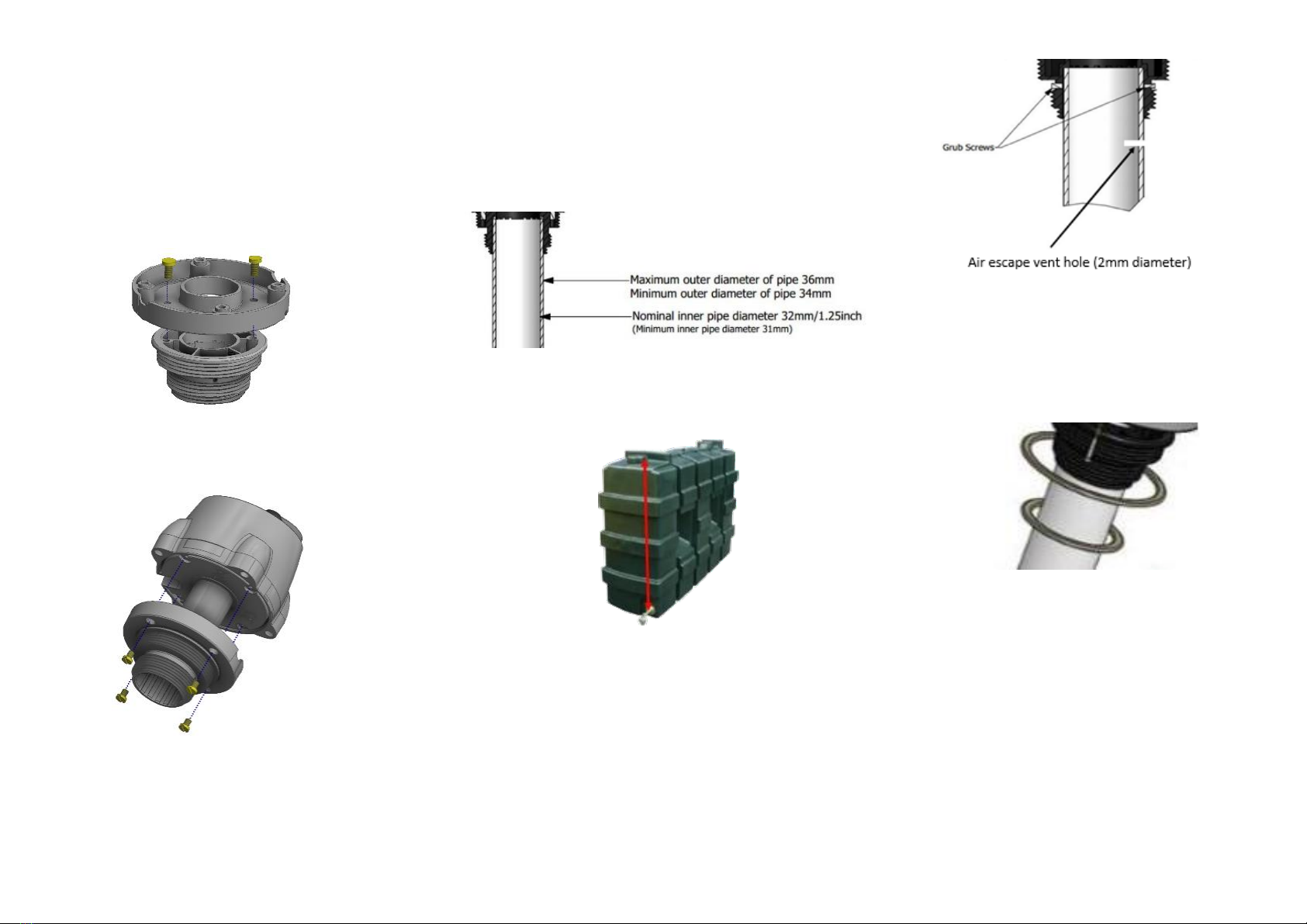
Appendix 3: Multi-Thread Adaptor
•For tanks that do not contain a suitably positioned threaded opening
on the top of the tank to hold the sensor, the pre-existing 2” adaptor
will need to be removed from the sensor and replaced with a multi-
thread adaptor, shown below.
•Remove the 2” adaptor by unscrewing the M3.5x10 Pozi screws x
4 that attach it to the base of the ultrasonic sensor.
•The Multi-Thread adaptor should be attached to the pairing
adaptor using No.8x13mm Pozi screws x 2.
•The pairing adaptor should then be attached to the ultrasonic
sensor base using the M3.5x10 Pozi screws x 4 that previously
held the 2” adaptor in place.
Note: This adaptor can also be used with the waveguide option but will
require a 36mm pipe. The waveguide pipe should be securely attached via
the two grub screws provided and hand tightened with an M1.5 Allen key
(Note: over-tightening the grub screws can damage the plastic).
7
Appendix 4: Multi-Thread Adaptor Waveguide
•For the waveguide option when using the Multi-Thread adaptor,
source a suitable pipe to act as the waveguide. This pipe should
conform the dimensions in the figure below in order to fit the
sensor. The recommended pipe material is PVC (domestic waste
pipe is often used). Other materials are possible but should be
checked for chemical resistance to fuel oil.
•Cross-section of waveguide pipe assembly:
•The pipe should be cleanly cut to length. The length required should
be measured from the top of the tank (where the sensor is to be
mounted) to that of the fuel outlet point (as shown).
Note: The bottom of the pipe should be a minimum of 5cm from the
base (floor) of the tank to prevent it from touching in the case of
tank dimensional changes due to temperature etc.
•The waveguide pipe should be securely attached via the two grub
screws and hand tightened with an M1.5 Allen key (Note: over-
tightening the grub screws can damage the plastic). Care should be
taken to keep the sensor and pipe vertically aligned and supported,
while fitting during the installation.
8
Note: Depending on the weight, length and surface finish of the
pipe, it may be necessary to glue it into position. In this case a hole
should be drilled near the top of the waveguide pipe, just below the
adapter, to ensure that any trapped air can exit.
•Insert the correctly sized rubber seal ring, as required for the
tank opening (supplied), and position it on the face of the
adapter that is screwed onto the top of the tank.
•Insert the whole assembly carefully into the tank, taking care not
to loosen the pipe, and fit into position. Hand tighten the
assembly until the rubber seal locks into position.
9
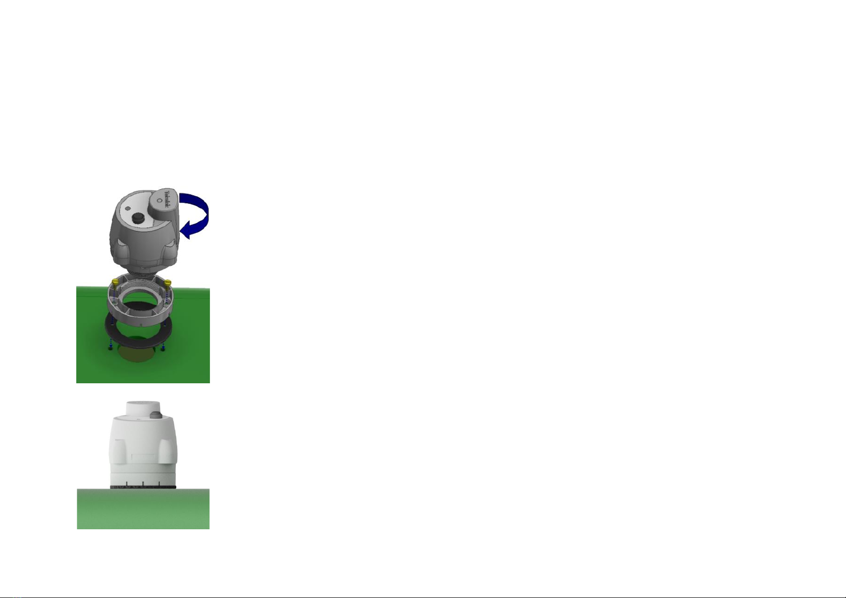
Appendix 5: Drilling procedure for Multi-Thread adaptor.
•Set up Multi-Thread adaptor as indicated in Appendix 3.
•Choose a flat spot on the top of the tank.
•Use a 45.5mm tapping drill to drill a 1 ½” BSP hole on the surface of
the tank.
•Place the foam gasket over the hole followed by the mounting
adaptor.
•Tighten on to tank with 2 stainless steel self-tapping, counter sunk
screws, supplied. Do not over tighten!
•Screw the sensor into the adaptor. Ensure that the sensor is vertical
on the tank and screwed correctly into the base and that the threads
have not crossed, to give a secure seal.
10
9-6133-02
Other TEKELEK Accessories manuals


