TEKELEK LoRaWAN User manual

LoRaWAN Ultrasonic Sensor
Installation Guide
Thank you for purchasing the Tekelek LoRaWAN Ultrasonic sensor which is
an ATEX certified LoRaWAN flexible and configurable battery-operated
level sensor with an integrated LoRaWAN radio.
Safety Information:
The LoRaWAN Ultrasonic sensor is ATEX compliant, but if installing in a
harsh environment first check local applicable regulatory and safety
guideline to ensure installer security. Please refer to the Short Instruction
Manual for more information on the warnings and hazards.
STEP 1: Installation
Note: For the LoRaWAN sensor, warnings detailed in the Short Instruction
Manual must be considered.
When possible, install the LoRaWAN sensor as high as possible off the
ground (>2meters is ideal).
The LoRaWAN sensor can be easily mounted in these different ways:
(screws & cable ties not provided)
•Wall mounting with M6 screws
•Vertical tube mounting with polyamide cable ties
•Horizontal tube mounting with polyamide cable ties
•Sensor may also be glued in place if required
These different configurations are detailed in the following steps.
1
1.1 Wall Mounting
The LoRaWAN sensor has a wall mount system for M6 screws. When
mounting, ensure that the antenna is vertical and avoid having the
antenna too close to another wall, or any obstacle.
Figure 1: Example of wall mounting
1.2 Vertical tube mounting
Mounting and installation of the LoRaWAN sensor on a vertical tube:
•Use 1 weather resistant polyamide cable tie (width < 5mm and
length > 250mm)
Follow these steps:
•Position the LoRaWAN sensor on the vertical tube
•Insert cable ties through holes on underside of the sensor
•Tighten the cable ties so that the sensor is held securely in place.
Figure 2: Example of vertical tube mounting
2
1.3 Horizontal tube mounting
Mounting and installation of the LoRaWAN sensor on a horizontal tube:
•Use 2 weather resistant polyamide cable ties (width < 5mm and
length > 250mm)
Follow these steps:
•Position the LoRaWAN sensor on the horizontal tube
•Tighten the cable ties so that the sensor is held securely in place.
Figure 3: Example of horizontal tube mounting
STEP 2: Antenna considerations
The position of the LoRaWAN sensor and its antenna is key in the
performance of the LoRa network. The position and the orientation of the
LoRaWAN sensor must be chosen carefully to offer the best performance.
Some recommendations are provided below.
•Orientation:
The antenna must be kept vertical, in the nominal position of the LoRaWAN
sensor.
•Metal plate, metallic parts:
Performance of the antenna may be degraded by metal parts within 20cm
above or beside the antenna
•Height / ground effect:
The ground has a significant impact on the radio signal attenuation. The
closer to the ground the LoRaWAN sensor is, the higher the attenuation will
be.
•Sensor interface:
The cable between the Rochester gauge and the LoRaWAN sensor should
be guided such that it is not close to the antenna. Also avoid creating any
loop with the cable, close to the LoRaWAN sensor enclosure.
3
STEP 3: Activation
Before installation the LoRaWAN sensor must first be registered to a
LoRaWAN network. Access to the LoRaWAN backend server is required to
verify that the unit has correctly joined the network.
•Once the sensor has been installed, activate the slide switch for
1 second to connect to the LoRaWAN network and upload a
status message. (See Figure 4)
•The LED will stay illuminated as the sensor registers:
−Red LED = The sensor is registering & connecting for the first time.
(Sensor is shipped in dormant state).
−Green LED = The sensor is already registered. The connection
process will take between 20 & 40 seconds.
•After the connection has completed, the LED will
flash on & off (to indicate whether the connection
was a success or failure). See STEP 4.
Figure 4: Slide Switch Activation
STEP 4: LED Patterns
Once the sensor has been installed successfully, it is recommended to
force a manual connection 4-5 times to test the strength of the radio
signal.
•Activate the slide switch for approximately 1 second, until the LED
turns green.
•Wait approximately 10-20 seconds and observe if the LED flashes
green or red.
•If the LED flashes red on greater than 50% of attempts, consider
elevating the sensor to improve the radio frequency performance.
See the following for description of Green/Red LED flash codes.
LED Radio Signal Strength Flash Codes:
LED Pattern
Function
Green X 3 Flashes
Excellent signal strength
Green X 2 Flashes
Good signal strength
Green X 1 Flash
Adequate signal strength
Alternate Green/Red Flash
Weak signal strength
4
LED Error Flash Codes:
LED Pattern
Function
Red X 1 Flash
Authentication or LoRaWAN join request fail
Red X 2 Flashes
No response from LoRaWAN network
Red X 3 Flashes
General Error. Please try again. If the error
persists, contact the supplier for support.
Red X 5 Flashes
Maximum number of allowed activations
exceeded (up to 6 per hour allowed).
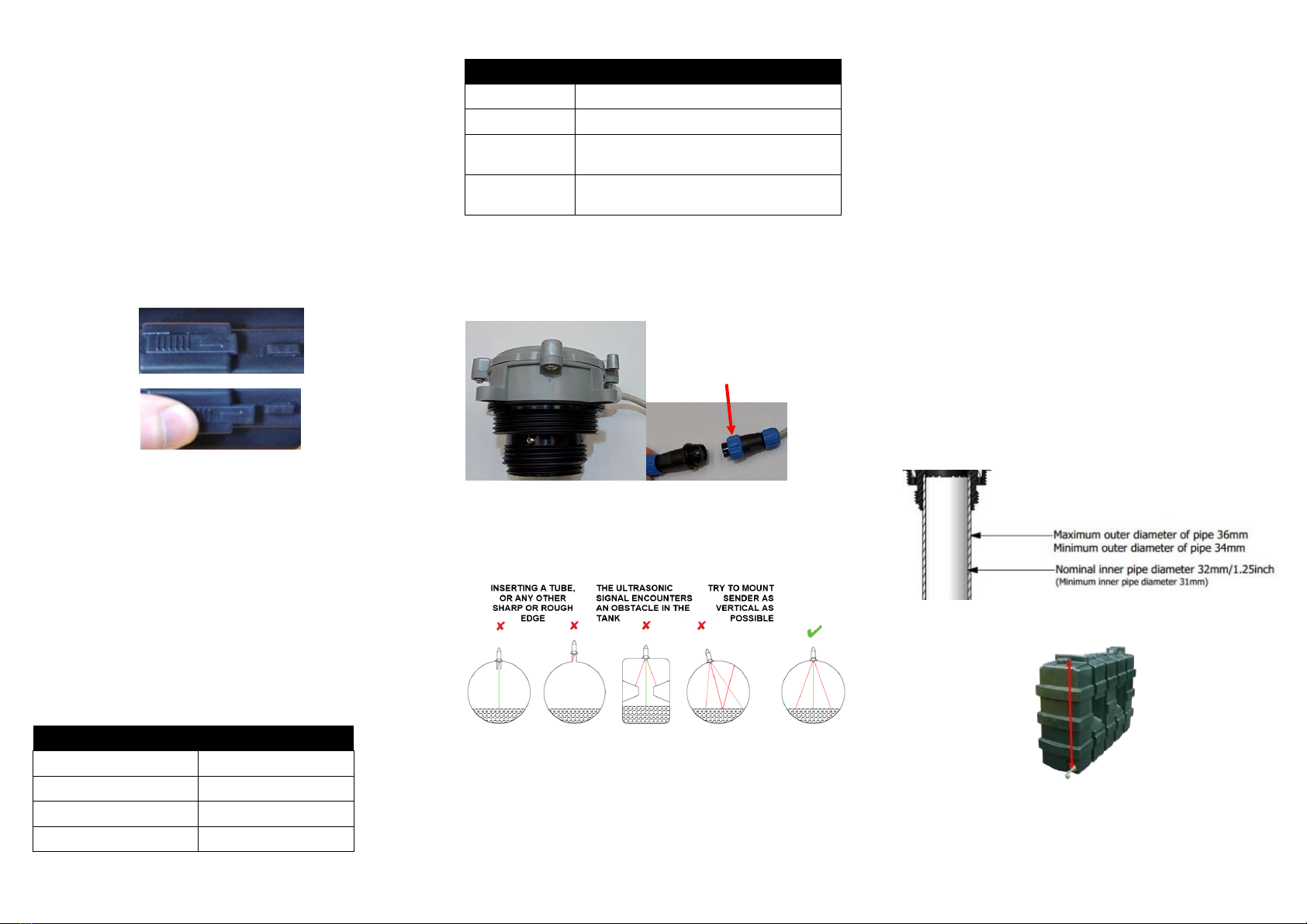
STEP 5: Fitting Ultrasonic gauge
The ATEX Ultrasonic level sensor has as standard a 3m cable with a
detachable connector to allow it to be separated from the data logger
host device and more easily screwed into place. It has a 2” and 1.5”
standard threaded NPT connection options.
The following outlines the Ultrasonic LoRaWAN sensor mounting options.
•The sensor must sit in a vertical position on top of the tank and be
fitted such that the sensor has a clear path to the tank contents.
Position it so that there are no internal obstructions that may
interfere with the ultrasonic signal.
•If obstacles cannot be avoided, then a waveguide may be required.
Please refer to Appendix 2 for further details.
•Locate a suitably positioned threaded opening on the top of the tank
to hold the sensor.
−The sensor will fit directly into threaded 1 ¼”, 1 ½” or 2” BSP (British
Standard Pipe) existing tank connections.
−Ensure that the gasket is placed, and that the sensor is screwed
correctly into the tank.
5
•For tanks that do not contain a suitably positioned threaded opening
on the top of the tank to hold the sensor, please refer to Appendix 1.
Appendix 1: Drilling Procedure
•Choose a flat spot on the top of the tank.
•Use a 45.5mm tapping drill to drill a 1 ½” BSP hole on the surface of
the tank.
•Place the foam gasket over the hole followed by the mounting
adaptor.
•Tighten on to tank with 2 stainless steel self-tapping, counter sunk
screws, supplied. Do not over tighten!
•Screw the sensor into the adaptor. Ensure that the sensor is
vertical on the tank and screwed correctly into the base and that
the threads have not crossed, to give a secure seal
Appendix 2: Waveguide
Note: The default sensor configuration is non-waveguide mode and
the measurements will be inaccurate unless a waveguide configuration
mode is used.
•Source a suitable pipe to act as the waveguide. This pipe should
conform the dimensions in the figure below in order to fit the
sensor. The recommended pipe material is PVC (domestic waste
pipe is often used). Other materials are possible but should be
checked for chemical resistance to fuel oil.
•Cross-section of waveguide pipe assembly:
•The pipe should be cleanly cut to length. The length required should
be measured from the top of the tank (where the sensor is to be
mounted) to that of the fuel outlet point (as shown).
Note: The bottom of the pipe should be a minimum of 5cm from the
base (floor) of the tank to prevent it from touching in the case of
tank dimensional changes due to temperature etc.
6
Locking nut
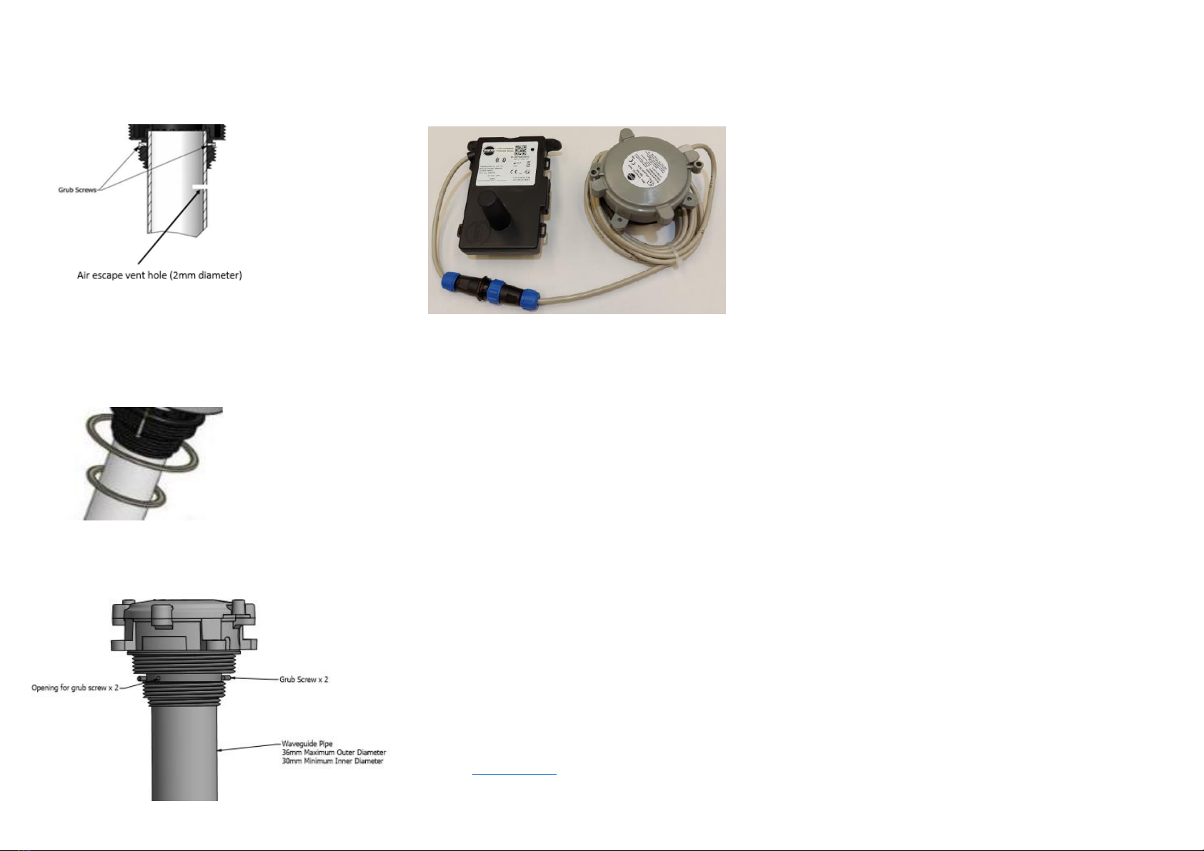
•The waveguide pipe should be securely attached via the two grub
screws and hand tightened with an M1.5 Allen key (Note: over-
tightening the grub screws can damage the plastic). Care should be
taken to keep the sensor and pipe vertically aligned and supported,
while fitting during the installation.
Note: Depending on the weight, length and surface finish of the
pipe, it may be necessary to glue it into position. In this case a hole
should be drilled near the top of the waveguide pipe, just below the
adapter, to ensure that any trapped air can exit.
•Insert the correctly sized rubber seal ring, as required for the
tank opening (supplied), and position it on the face of the
adapter that is screwed onto the top of the tank.
•Insert the whole assembly carefully into the tank, taking care not
to loosen the pipe, and fit into position. Hand tighten the
assembly until the rubber seal locks into position.
7
Addition documentation:
•9-5854 Short Instructional Manual
•9-6091 TEK 790F LoRaWAN ATEX Ultrasonic Head Sensor User Manual
•9-6076 TEK 865 Ultrasonic Head Installation Guide
•9-6078 TEK 865 Ultrasonic Head User Manual
For more information on the Tekelek LoRaWAN sensors please visit our
website www.tekelek.com where a link to our YouTube page can also be
found.
9-6088-02
8
9
Other manuals for LoRaWAN
1
Other TEKELEK Accessories manuals


