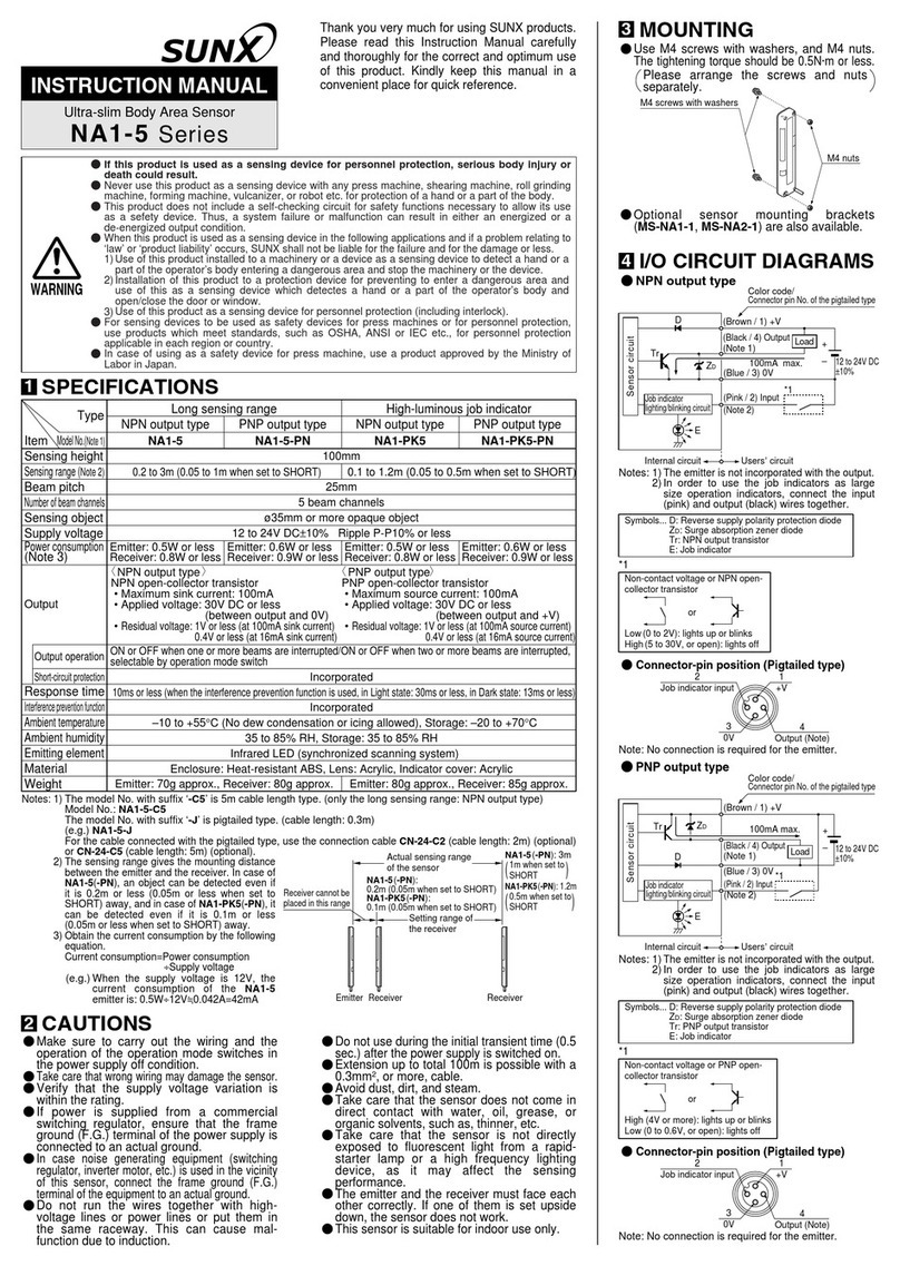
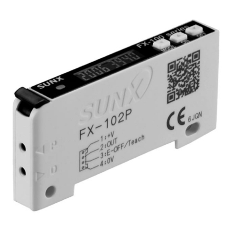
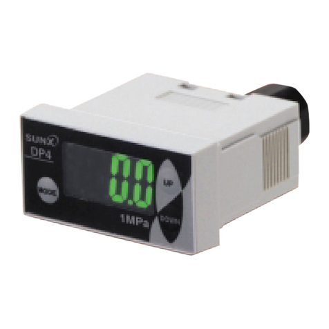
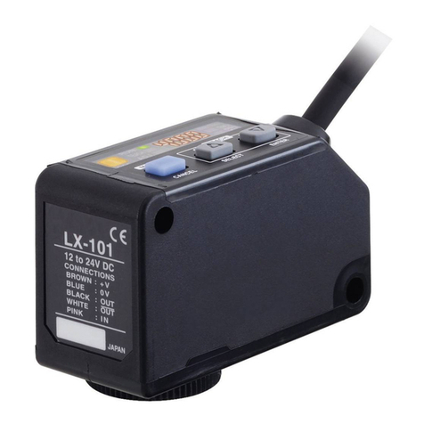
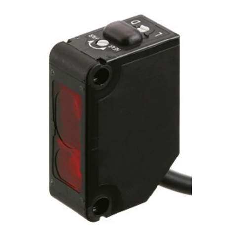
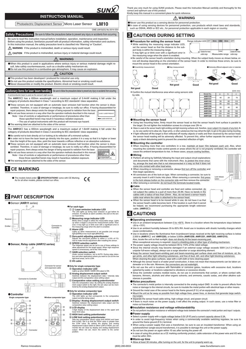
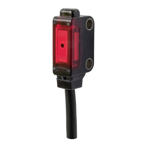
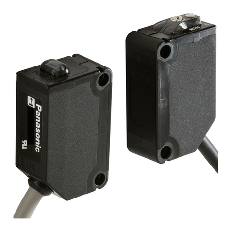
Sunx FX-101 User manual

Thank you very much for using SUNX products. Please read this Instruc-
tion Manual carefully and thoroughly for the correct and optimum use of this
product. Kindly keep this manual in a convenient place for quick reference.
FX-100 Series
INSTRUCTION MANUAL
Digital Fiber Sensor
Photoelectric Sensor
MJE-FX100 No.0007-43V
WARNING
Never use this product as a sensing device for personnel protection.
In case of using sensing devices for personnel protection, use products
which meet laws and standards, such as OSHA, ANSI or IEC etc., for
personnel protection applicable in each region or country.
Ɣ
Ɣ
+RZWRFRQQHFWWKH¿EHUFDEOH
%HVXUHWR¿WWKHDWWDFKPHQWWRWKH¿EHUV¿UVWEHIRUHLQVHUWLQJWKH¿EHUVWRWKH
DPSOL¿HU)RUGHWDLOVUHIHUWRWKH,QVWUXFWLRQ0DQXDOHQFORVHGZLWKWKH¿EHUV
1. Snap the fiber lock lever down, till it stops
completely.
2. Insert the fiber cables slowly into the inlets
until they stop. (Note 1)
5HWXUQWKH¿EHUORFNOHYHUWRWKHRULJLQDOSRVL-
tion, till it stops.
1
3
2
Fiber lock
lever
Fiber
MOUNTING
2
+RZWRPRXQWWKHDPSOL¿HU
)LWWKHUHDUSDUWRIWKHPRXQWLQJVHFWLRQRIWKH
DPSOL¿HURQDPPZLGWK',1UDLO
2. Press down the rear part of the mounting
VHFWLRQRIWKHXQLWRQWKHPPZLGWK',1UDLO
DQG¿WWKHIURQWSDUWRIWKHPRXQWLQJVHFWLRQ
WRWKH',1UDLO
1
2
35mm width DIN rail
:KHQXVLQJD',1UDLO!
+RZWRUHPRYHWKHDPSOL¿HU
3XVKWKHDPSOL¿HUIRUZDUG
/LIWXSWKHIURQWSDUWRIWKHDPSOL¿HUWRUHPRYH
it.
1
2
:KHQXVLQJVFUHZVZLWKZDVKHUV!
Use M3 screws with washers for mounting.
7KHWLJKWHQLQJWRUTXH VKRXOGEH 1ÂPRU
less.
Ɣ
M3 screw
with washer
1RWH 7DNHFDUHWKDWLIWKHIURQWSDUWLVOLIWHGZLWKRXWSXVKLQJWKHDPSOL¿HUIRUZDUGWKH
hook on the rear portion of the mounting section is likely to break.
1RWHV,QFDVHWKH¿EHUFDEOHVDUHQRWLQVHUWHGWRDSRVLWLRQZKHUHWKH\VWRSWKH
VHQVLQJUDQJHUHGXFHV6LQFHDÀH[LEOH¿EHULVHDVLO\EHQWWDNHFDUHZKHQ
it is inserted.
:LWKWKHFRD[LDOUHÀHFWLYHW\SH¿EHUVXFKDV)'* or )')0, insert the
VLQJOHFRUH¿EHUFDEOHLQWRWKHEHDPHPLWWLQJ LQOHW ³3´DQGWKHPXOWLFRUH
¿EHUFDEOHLQWRWKHEHDPUHFHLYLQJLQOHW³'´,IWKH\DUHLQVHUWHGLQUHYHUVH
the sensing performance will deteriorate.
3$57'(6&5,37,21
1
MODE key
ON key /
Set value UP key
Operation indicator
(Orange)
OFF key /
Set value DOWN key
Digital display (Green)
(Threshold value)
Digital display (Red)
(Incident light intensity)
2SHUDWLQJSRUWLRQ!
02'(NH\ ON key /
Set value UP key
2))NH\
6HWYDOXH'2:1NH\
Â6HOHFWLRQRIVHWWLQJLWHPV
Â&RQ¿UPDWLRQRIVHWFRQWHQWV
Â6HOHFWLRQRIVHWWLQJFRQWHQWV
Â6HWWLQJVLQWHDFKLQJPRGH
1RWH &DQFHOODWLRQLV SRVVLEOHZKHQSUHVVLQJ02'(NH\IRU VHFRUPRUHLQSUR-
FHVVRIVHWWLQJVH[FHSWIRU581PRGHWKHQUHWXUQVWR581PRGH
Release
lever
Note: Take care that if the connector is pulled out without
pressing the release lever, cable or connector may
break.
'LVFRQQHFWLRQPHWKRG
Pressing the release lever of the cable with con-
nector, pull out the connector.
Ɣ
&RQQHFWRUSLQDUUDQJHPHQW!
Connector pin No. Terminal name
1+V
2 Output
3([WHUQDOLQSXW
40V
1
2
3
4
Insert the cable with connector &1$&Ƒinto
this product's connector area as shown in the
right figure.
Ɣ
WIRING
3
&RQQHFWLRQPHWKRG
Cable with
connector
CN-14A-CƑ
58102'(
5
7KUHVKROGYDOXH¿QHDGMXVWPHQWIXQFWLRQ
)LQHDGMXVWPHQWRIWKUHVKROGYDOXHFDQEHGRQHZKHQLQ581PRGH
3UHVVWKHVHWYDOXH83NH\RUVHWYDOXH'2:1NH\WRFKDQJHWKUHVKROG
value. (Hold down the key to make the value change faster.)
The threshold value is stored after 3 sec.
Ɣ
Ɣ
Ɣ
<When in RUN mode>
Incident light
intensity
Threshold
value
<When turning ON the power>
Emission
frequency
Product
name
<RUN mode>
Incident light
intensity
Threshold
value
Automatic
When turning ON the power, the product name is indicated on the green
digital display, while the emission frequency is indicated on the red digital
display. Then switches into RUN mode [digital display (green: threshold
value, red: incident light intensity)].
Ɣ
'LJLWDOGLVSOD\!
:KHQVHOHFWLQJHPLVVLRQ KDOWLQ WKHH[WHUQDO LQSXWVHWWLQJPRGHDQGUH-
FHLYLQJWKHVLJQDOH[WHUQDOO\³ ´LVLQGLFDWHGRQWKHUHGGLJLWDOGLVSOD\
:KHQVHOHFWLQJ(&2LQWKHH[WHUQDOLQSXWVHWWLQJPRGHNH\RSHUDWLRQRQ
WKHPDLQERG\LVLQYDOLGGXULQJH[WHUQDOLQSXW
:KHQVHOHFWLQJSRLQWWHDFKLQJLQWKHH[WHUQDOLQSXWVHWWLQJPRGH³ ´
is indicated on the green digital display after inputting the first point.
:KHQ(&2VHWWLQJPRGHLV21WKHGLJLWDOGLVSOD\WXUQVRIILQDSSUR[
sec. In case of lighting up the digital display again, press any key for 2
sec. or more.
)RUWKHVHWWLQJVRIH[WHUQDOLQSXWDQG(&2UHIHUWR³ 35202'(´
Ɣ
Ɣ
Ɣ
Ɣ
Ɣ
,2&,5&8,7',$*5$06
131RXWSXWW\SH!
+
–
8V
*1
Main circuit
Internal circuit Users’ circuit
100mA max.
(Brown) +V
(Black) Output
(Blue) 0V
(White) External input
Color code of cable with connector
12 to 24V DC
±10%
Load
Connector pin No.
313RXWSXWW\SH!
*2
Main circuit
Internal circuit Users’ circuit
100mA max.
(Brown) +V
(Black) Output
(Blue) 0V
(White) External input
Color code of cable with connector
+
–
12 to 24V DC
±10%
Load
Connector pin No.
*1
Non-voltage contact or NPN open-collector transistor
or
+LJK9WR9'&RU2SHQ,QYDOLG
/RZ>WR9'&6RXUFHFXUUHQWP$RUOHVV@9DOLG
*2
Non-voltage contact or PNP open-collector transistor
or
+LJK>9WR9'&6LQNFXUUHQWWRP$RUOHVV@9DOLG
/RZWR9'&RU2SHQ,QYDOLG
'LJLWDO¿EHUVHQVRU);VHULHVKDVEHHQPRGL¿HGVLQFH
SURGXFWLRQLQ 'HFHPEHU+HQFHWKLVLQVWUXFWLRQ
PDQXDOKDVEHHQFKDQJHGWRUHÀHFWWKHPRGL¿FDWLRQV

.H\ORFNIXQFWLRQ
The keylock function prevents key operations so that the conditions set
in each setting mode are not inadvertently changed.
,QWKHNH\ORFNFRQGLWLRQ³ ´LVGLVSOD\HGZKHQSUHVVLQJDQ\NH\
Ɣ
Ɣ
<When in RUN mode>
[Keylock released]
Press for 2 sec. or more
Auto-
matic
Auto-
matic
<When in RUN mode>
[Keylock set]
Press for 2 sec.
Automatic
6(77,1*02'(
6
Emission
frequency 0
Emission
frequency 1
<Setting mode>
<Output operation setting mode>
(Light-ON)(Dark-ON)
<Emission amount setting mode>
<Teaching mode>
For details, refer to “
TEACHING MODE.”
7
<Timer operation setting mode>
<Emission frequency setting mode (Note 2)>
(Without timer)
(Timer delay) (Timer delay)
<Timer delays setting mode>
: Select timer delays from 1ms, 5ms, 10ms, 20ms, 40ms, 50ms,
100ms, 500ms, and 1,000ms.
<Timer delays setting mode>
ON delay
timer
OFF delay
timer
Automatic
<RUN mode>
Press for 2 sec.
<RUN mode>
In case of FX-101ƑIn case of FX-102ƑIn case of FX-101Ƒ
: Select emission frequency from
“” “ ” “ ,” and “”
: Select emission frequency from
“” “” “,” and “”
In case of FX-102Ƒ
(Level 2)(Level 3) (Auto + Level 3)
(Note 1)
(Level 1)
Setting mode appears after SUHVVLQJ 02'(NH\IRU VHF LQ581
PRGH.
581PRGHDSSHDUVDIWHU02'(NH\LVSUHVVHGIRUVHFLQSURFHVVRI
VHWWLQJ+RZHYHUFKDQJHG LWHPVEHIRUH SUHVVLQJ02'(NH\IRUVHF
have been set.
Ɣ
Ɣ
Notes: 1)
:KHQVHOHFWLQJ$XWRGLVSOD\HGZLWK³ ´ SURSHU OLJKW LQWHQVLW\ ´ SURSHU OLJKW LQWHQVLW\ , proper light intensity (³ ´ ³ ´
or ³ ´LV DXWRPDWLFDOO\ GHFLGHG ZKHQ RQO\ WKH OLPLW WHDFKLQJ LV VHW is automatically decided when only the limit teaching is set. ((³ ´LV
indicated at first selecting.)
In Auto, emission amount is automatically set to let the incident light intensity
in proper range (1000 to 3800).
2) The operation indicator and the beam-emitting inlet blink while setting emis-
sion frequency. (When emission frequency 0 is set, they light up.) The blink-
ing cycle depends on each emission frequency.
(PLVVLRQIUHTXHQF\IDVWļ(PLVVLRQIUHTXHQF\VORZ
Setting item
)DFWRU\VHWWLQJ
'HVFULSWLRQ
Teaching
mode
Threshold value can be set in 2-point teaching, limit
teaching or full-auto teaching.
)RUGHWDLOVUHIHUWR³ 7($&+,1*02'(´
Output operation
setting mode
/LJKW21RU'DUN21FDQEHVHW
Timer operation
setting mode
:LWKRXWWLPHU21GHOD\WLPHURU2))GHOD\WLPHUFDQEH
set.
Timer delays
setting mode
:KHQVHWWLQJ21GHOD\WLPHURU 2)) GHOD\WLPHULQWKH
timer operation setting mode, timer delays can be set.
When timer is not set, this mode is not displayed.
,QFDVHRIOLPLWWHDFKLQJ
This is the method of setting the threshold value by teaching only the ob-
MHFWDEVHQWFRQGLWLRQVWDEOHLQFLGHQWOLJKWFRQGLWLRQ7KLVLVXVHGIRUGHWHF-
WLRQLQWKHSUHVHQFHRIDEDFNJURXQGERG\RUIRUGHWHFWLRQRIVPDOOREMHFWV
:KHQVHOHFWLQJ³$XWR´GLVSOD\HGZLWK³ ´LQWKHHPLVVLRQDPRXQWVHW-
WLQJPRGHSURSHUOLJKWLQWHQVLW\FDQEHDXWRPDWLFDOO\VHW)RUWKHVHWWLQJ
PHWKRGUHIHUWR³ 6(77,1*02'(´
Ɣ
Ɣ
<Teaching mode>
or
ƒ3UHVV2))NH\WKHWKUHVKROGYDOXHLVVKLIWHGWRORZHUVLGHWZLFH
ZKHQXVLQJWKUXEHDPW\SHILEHUDQGSUHVV21NH\WKHWKUHVKROG
YDOXHLVVKLIWHGWRKLJKHU
VLGHWZLFHZKHQXVLQJ
UHIOHFWLYHW\SHILEHU
7KUXEHDPW\SH 5HIOHFWLYHW\SH
%DFN
JURXQG
$XWRPDWLF
or
$XWRPDWLF
ƒ
7KHSUHVHQWLQFLGHQWOLJKWLQWHQVLW\EOLQNVLQUHGDWWKHGLJLWDOGLVSOD\
ƒ3UHVV21NH\RU2))NH\ZKLFKLVSUHVVHGLQWKHSUHYLRXVVWHS
)RUH[DPSOHZKHQ21NH\LVSUHVVHGLQWKHSUHYLRXVVWHSSUHVV
21NH\DJDLQIRUWKHVHFRQGWLPH
7KHLQFLGHQWOLJKWLQWHQVLW\DWWKHVHFRQGNH\LQSXWLVQRWUHODWHGWRWKH
WKUHVKROGYDOXH
ƒ7KHVHWWLQJLVGRQH 3UHVV
7KUHVKROG
YDOXH
High
/RZ
7KUHVKROGYDOXH
7KUHVKROGYDOXH
3UHVV
15%
15%
,QFLGHQWOLJKWLQWHQVLW\
ZLWKREMHFWDEVHQW
ƒ7KHVHWWKUHVKROGYDOXHLVLQGLFDWHGRQWKHJUHHQGLJLWDOGLVSOD\
7KHWKUHVKROGYDOXHGHSHQGVRQWKHVKLIWDPRXQW)RUVHWWLQJPHWKRG
RIWKHVKLIWDPRXQWUHIHUWR6KLIWVHWWLQJPRGH!LQ³PRO MODE´
ƒ0DUJLQIRUWKHWKUHVKROGYDOXH
WRWKHLQFLGHQWOLJKWLQWHQVLW\LV
LQGLFDWHGRQWKHUHGGLJLWDO
GLVSOD\:KHQWKHPDUJLQLV
RUPRUH³´LV
GLVSOD\HG
8
ƒ5HIHUHQFHLQFLGHQWOLJKWLQWHQVLW\LVVHWE\WKHILUVWNH\LQSXWDQG
LQGLFDWHGRQWKHJUHHQGLJLWDOGLVSOD\
&DQFHOODWLRQRIWKHVHWWLQJIRUWKHUHIHUHQFHLQFLGHQWOLJKWLQWHQVLW\LV
SRVVLEOHZKHQ02'(NH\LVSUHVVHG
7($&+,1*02'(
7
Make sure that detection may become unstable if less margin is applied in
the use environment when teaching.
,QFDVHRISRLQWWHDFKLQJ
This is the method of setting the threshold value by teaching two points, corresponding
WRREMHFWSUHVHQWDQGREMHFWDEVHQWFRQGLWLRQV1RUPDOO\VHWWLQJLVGRQHE\WKLVPHWKRG
7KHRXWSXWRSHUDWLRQVHWWLQJRI/LJKW21RU'DUN21LVUHÀHFWHGDXWRPDWLFDOO\
Ɣ
Ɣ
[For output ON when in object absent condition]
Automatic
<Teaching mode>
Thru-beam type
Light interrupted
condition
Light received condition
Mark
Reflective type
Base
Automatic
Automatic
<Teaching mode>
[For output ON when in object present condition]
Thru-beam type
Light received condition
Light interrupted condition
Mark
Reflective type
Base
Automatic
ƒ
The setting is done.
ƒ
The threshold value which is set between the first and the second
incident light intensity is indicated on the green digital display.
ƒ0DUJLQIRUWKHWKUHVKROGYDOXHWRWKHILUVWRUWKHVHFRQGLQFLGHQWOLJKW
intensity is indicated on the red digital display.
ƒ3UHVV21NH\LQREMHFW
absent condition.
ƒ
The present incident light
intensity blinks in red at
the digital display.
ƒ3UHVV2))NH\LQREMHFW
present condition.
ƒ
The setting is done.
ƒ3UHVV21NH\LQREMHFW
present condition.
Thru-beam type
Light interrupted
condition
Light received condition
Mark
Reflective type
Base
Thru-beam type
Light received condition
Light interrupted condition
Mark
Reflective type
Base
ƒ
The present incident light
intensity blinks in red at
the digital display.
ƒ3UHVV2))NH\LQREMHFW
absent condition.
ƒ
The threshold value which is set between the first and the second
incident light intensity is indicated on the green digital display.
ƒ
Margin for the threshold value to the first or the second incident light
intensity is indicated on the red digital display. When the margin is
200% or more, “ ” is displayed.
ƒ
The first incident light intensity is set and indicated on the green digital display.
Cancellation of the setting for the first incident light intensity is
SRVVLEOHZKHQ02'(NH\LVSUHVVHG
ƒ
The first incident light intensity is set and indicated on the green digital display.
Cancellation of the setting for the first incident light intensity is
SRVVLEOHZKHQ02'(NH\LVSUHVVHG
Setting item
)DFWRU\VHWWLQJ
'HVFULSWLRQ
Emission
amount set-
ting mode
In case incident light intensity is saturated, emission amount can be reduced.
The reduced intensity state can also be released.
/HYHO³ ´1RUPDOHPLVVLRQDPRXQWOHYHO
Level 2 ³ ´(PLVVLRQDPRXQWOHYHOîDSSUR[
Level 1 ³ ´(PLVVLRQDPRXQWOHYHOîDSSUR[
:KHQVHOHFWLQJ$XWRGLVSOD\HGZLWK³ ´ 2QO\ LQ WKH´2QO\LQWKH
limit teaching, proper light intensity is automatically set.
Emission
frequency
setting
mode
FX-102Ƒ
FX-101Ƒ
:KHQXVLQJWKH¿EHUKHDGVLQSDUDOOHOLQWHUIHUHQFHFDQEH
prevented by setting different emission frequency. How-
ever, when emission frequency 0 is set, interference can-
not be prevented. Response time corresponds to emission
IUHTXHQF\)RUGHWDLOVUHIHUWR³ 63(&,),&$7,216´

,QFDVHRIIXOODXWRWHDFKLQJ
)XOODXWRWHDFKLQJLVXVHGZKHQLWLVGHVLUHGWRVHWWKHWKUHVKROGYDOXHZLWK-
RXWVWRSSLQJWKHDVVHPEO\OLQHZLWKWKHREMHFWLQWKHPRYLQJFRQGLWLRQ
Ɣ
ƒ+ROGGRZQ21NH\RU2))NH\
ƒ7KHVHWWLQJLVGRQH
ƒ³´DSSHDUVLQWKHJUHHQGLJLWDOGLVSOD\DIWHUDSSUR[VHFDQG
VWDUWVVDPSOLQJWKHLQFLGHQWOLJKWLQWHQVLW\IURPWKDWSRLQW
ƒ7KHWKUHVKROGYDOXHLVVHWZKHQ21NH\RU2))NH\LVUHOHDVHG
7HDFKLQJPRGH!
+ROGGRZQ
RU
$XWRPDWLF
$XWRPDWLF
ƒ7KHVHWWKUHVKROGYDOXHLVLQGLFDWHGRQWKHJUHHQGLJLWDOGLVSOD\
ƒ0DUJLQIRUWKHWKUHVKROGYDOXHWRWKHLQFLGHQWOLJKWLQWHQVLW\LV
LQGLFDWHGRQWKHUHGGLJLWDOGLVSOD\
:KHQWKHPDUJLQLVRUPRUH³´LVGLVSOD\HG
35202'(
8
352PRGHDSSHDUVDIWHUSUHVVLQJ02'(NH\IRUVHFLQ581PRGH
581PRGHDSSHDUV DIWHUSUHVVLQJ 02'(NH\ IRUVHFLQSURFHVVRI
VHWWLQJ+RZHYHUFKDQJHG LWHPVEHIRUH SUHVVLQJ02'(NH\IRUVHF
have been set.
Ɣ
Ɣ
(Emission halt)
<External input setting mode>
<Threshold value follow-up cycle setting mode>
(Limit teaching [+]) (Limit teaching [-]) (Full-auto teaching)
(ECO)(2-point teaching)
<Shift setting mode>
(15%)
: Select the shift amount from 0 to 80%
<PRO mode>
<RUN mode>
Press for 4 sec.
(OFF)
(Under 60 sec.)
<Threshold value-storing setting mode>
(OFF) (ON)
(10 to 60 min. or less)(1 to 9 min. or less)
Automatic
<GETA function setting mode>
<Inverting digital display setting mode>
(ON)(OFF)
<ECO setting mode>
(ON)(OFF)
<Threshold value margin setting mode>
(OFF)
(Red blinks)(Green blinks)
<Setting copy mode>
: Select a target value from 0 to 2,000
(100 unit each) to correct the incident
light intensity.
(OFF) (SET)
(2,000)
(Red and Green blink)
(Incident light intensity test)
Threshold value-storing setting mode is not indicated
unless any of “ ,” “ ,” “ ” or “ ” is
set at the external input setting mode.
Alert output of external
input teaching
Alert output of external input teaching does not
operate unless any of “ ,” “ ” or
“ ” is set at the external input setting mode.
Setting item
)DFWRU\VHWWLQJ
'HVFULSWLRQ
Shift setting
mode
6KLIWDPRXQWFDQEHVHOHFWHGIURPWRLQWKHOLPLW
teaching.
6HOHFWZKHQLWLVGHVLUHGWRVHWWKHSUHVHQWLQFLGHQW
light intensity as a threshold value.
([WHUQDOLQSXW
setting mode
([WHUQDOLQSXWFDQEHVHOHFWHGIURPHPLVVLRQKDOWOLPLW
teaching [+], limit teaching [-], full-auto teaching, ECO
(Note 1), 2-point teaching or emission amount test.
:KHQVHWWLQJWKHLQFLGHQWOLJKWLQWHQVLW\ WHVW ³ ´
RXWSXWWXUQV21 2))HYHU\PVZKHQWKHUDWHRI
incident light intensity and threshold value is less than
half of the set shift amount IRUH[DPSOHZKHQWKHUDWH
of incident light intensity and threshold value is within
IRU RI VKLIW DPRXQWIRURIVKLIWDPRXQWDWH[WHUQDOLQSXW
Threshold
value-storing
setting mode
(Note 2)
Threshold value set at the limit teaching, full-auto
teaching or 2-pointWHDFKLQJE\H[WHUQDOLQSXWLVVWRUHG
When selecting Auto in the emission amount setting
mode, the set emission amount level is also stored.
Threshold value
follow-up cycle
setting mode
(Note 3)
:KHQLQFLGHQWOLJKWLQWHQVLW\H[FHHGVWKUHVKROGYDOXH
this mode can change the threshold value with each
set cycle depending on variations of the incident light
intensity. The follow-up shift amount is same as the
one set in the shift setting mode.
However, the threshold value is not stored.
GETA function
setting mode
1RWH
Variations can be reduced by correcting the present in-
FLGHQWOLJKWLQWHQVLW\LQHDFKDPSOL¿HUWRDWDUJHWYDOXH
Target value to offset incident light intensity can be
selected from 0 to 2,000 by 100 unit each.
)RUH[DPSOHLIWKHWDUJHWYDOXHLV VHWWRZKHQ
WKHLQFLGHQWOLJKWLQWHQVLW\LV WKH LQFLGHQWOLJKW
intensity becomes 2,000.
ECO setting
mode
It is possible to light up / turn off the digital display.
When ECO setting mode is ON, the display turns off in
DSSUR[VHFLQ581PRGH7ROLJKWXSWKHGLVSOD\
again, press any key for 2 sec. or more.
Inverting dig-
ital display
setting mode
'LJLWDOGLVSOD\FDQEHLQYHUWHG
Threshold
value mar-
gin setting
mode
Margin for threshold value to the present incident light
intensity can be checked. When there is no margin, it
is possible to make the digital display blink.
³ ´*UHHQEOLQNV
³ ´5HGEOLQNV
³ ´5HGDQG*UHHQEOLQN
³ ´ When conducting limit teaching or 2-point
WHDFKLQJE\H[WHUQDOLQSXWLQFDVHWKH UDWH
of reference incident light intensity and
WKUHVKROGYDOXHDIWHUWHDFKLQJLV RU
more, or in case it is less than half of the
VKLIWDPRXQWRXWSXWWXUQV21 2)) HYHU\
100ms. (Note 6)
Setting copy
mode
7KHVHWWLQJVRIWKHPDVWHUVLGHDPSOL¿HUFDQEHFRSLHG
WRWKHVODYHVLGHDPSOL¿HU
)RUGHWDLOVUHIHUWR³ 6(77,1*&23<)81&7,21´
Reset mode Returns to default settings (factory settings).
1RWHV:KHQ(&2LVVHOHFWHGDWWKHH[WHUQDOLQSXWVHWWLQJPRGHNH\RSHUDWLRQRQ
WKHPDLQERG\LVLQYDOLGGXULQJH[WHUQDOLQSXW
2)
7KLVPRGHLVQRWLQGLFDWHGXQOHVVDQ\RI³ ´³ ´³ ´RU³ ´
LVVHWDWWKHH[WHUQDOLQSXWVHWWLQJPRGH
,IWKHLQFLGHQWOLJKWLQWHQVLW\ EHFRPHV³´RUOHVVWKHIROORZXS RSHUDWLRQ
stops. In that condition, threshold value [digital display (green)] blinks.
7KLVIXQFWLRQFDQEHXVHGZKHQWKUXEHDPW\SHRUUHWURUHÀHFWLYHW\SH¿EHULV
DSSOLHGWRWKLVSURGXFW,IUHÀHFWLYHW\SH¿EHULVDSSOLHGWKHIXQFWLRQFDQQRW
be used depending on use conditions.
,ISUHVVLQJ02'(NH\LQ581PRGHZKHQ*(7$IXQFWLRQLVXVHGWKHLQFL-
dent light intensity before setting GETA function is displayed on the red digi-
WDOGLVSOD\IRUDSSUR[VHF
:KHQ*(7$IXQFWLRQLVXVHGLQVDWXUDWLRQRILQFLGHQWOLJKWLQWHQVLW\RU
PRUH³ ´LVLQGLFDWHGRQWKHUHGGLJLWDOGLVSOD\&RUUHFWLRQYDOXHLVXS
to 4,000.
6)
7KLVPRGHGRHVQRWRSHUDWHXQOHVVDQ\RI³ ´³ ´RU³ ´LVVHW
DWWKHH[WHUQDOLQSXWVHWWLQJPRGH
<Threshold value margin setting mode>
<RUN mode>
(YES)(NO)
<Reset mode>
(YES)(NO)
<Setting copy mode>
(READY)
: Cancellation is possible when
pressed for 2 sec. or more.
Turn the power off when copying the settings.
48,&.6(77,1*)81&7,21
11
7DEOHRITXLFNVHWWLQJQXPEHUV!
Simply by selecting a setting number, output operation, emission
amount, timer, and emission frequency can be set.
)RUWKHVHWWLQJQXPEHUVUHIHUWR7DEOHRITXLFNVHWWLQJQXPEHUV!.
Ɣ
Ɣ
<When in RUN mode>
Press for 2 sec.
(Note 1)
: Select a quick setting number
(Quick setting)
: Select emission frequency
(Emission frequency setting)
(Note 1)
Automatic
Notes: 1) &DQFHOODWLRQLVSRVVLEOHZKHQSUHVVLQJ02'(NH\IRUVHFRUPRUHEHIRUH
¿QDOL]LQJWKHQUHWXUQVWR581PRGH.
2)
When the present setting is out of the quick setting range, ³ ´ is shown.
When ³
´
is selected, the set content is not changed.
No. Output
operation
Emission amount
setting
Timer
-00- '21 2)) non
-01- '21 ON non
-02- '21 2)) ofd 10ms
-03- '21 ON ofd 10ms
-04- '21 2)) ofd 40ms
'21 ON ofd 40ms
-06- '21 2)) ond 10ms
'21 ON ond 10ms
-08- '21 2)) ond 40ms
-09- '21 ON ond 40ms
No. Output
operation
Emission amount
setting
Timer
-10- L-ON ON ond 40ms
-11- L-ON 2)) ond 40ms
-12- L-ON ON ond 10ms
-13- L-ON 2)) ond 10ms
-14- L-ON ON ofd 40ms
L-ON 2)) ofd 40ms
-16- L-ON ON ofd 10ms
L-ON 2)) ofd 10ms
-18- L-ON ON non
-19- L-ON 2)) non
6(77,1*&23<)81&7,21
7KLVFDQFRS\WKHVHWWLQJVRIWKHPDVWHUVLGHDPSOL¿HUWRWKHVODYHVLGH
DPSOL¿HU
Ɣ
Be sure to use the setting copy function between the identical models.
This function cannot be used between different models.
Only one sensor can be connected on slave side with a master side
sensor for the setting copy function.
Threshold value, output operation setting, timer operation setting, timer
VHWWLQJHPLVVLRQDPRXQW VHWWLQJVKLIW VHWWLQJH[WHUQDO LQSXWVHWWLQJ
threshold value-storing setting, ECO setting, inverting digital display set-
ting, and threshold value margin setting can be copied.
Ɣ
Ɣ
Ɣ
6HWWLQJSURFHGXUHV!
Master side amplifier
Slave side amplifier
(Brown) V
(Brown) V
(Blue) 0V
(Blue) 0V
(White) External input
(Black) Input
(Black) Input
Color code of cable with connector
Power supply
7RFDQFHOWKHVHWWLQJFRS\PRGHRIWKHPDVWHUVLGHDPSOL¿HU!
:KLOHWKHVODYHVLGHDPSOL¿HULVGLVFRQQHFWHGWXUQRQWKHSRZHURIWKH
PDVWHUVLGHDPSOL¿HU
3UHVV02'(NH\IRUDSSUR[VHF
4. Turn on the master side amplifier and the slave side amplifier at the
same time. (Note)
³ ´LVVKRZQRQWKHJUHHQGLJLWDOGLVSOD\RIWKHPDVWHUVLGHDPSOL¿HU
and 4-digit code is shown on the red digital display of it, then the copying
starts.
:KHQWKHFRS\LQJLV FRPSOHWHG³ ´LV VKRZQRQWKHJUHHQGLJLWDO
GLVSOD\RIWKHVODYHVLGHDPSOL¿HUZKLOHWKHGLJLWFRGHWKHVDPHFRGH
DVWKHPDVWHUVLGHDPSOL¿HULVVKRZQRQWKHUHGGLJLWDOGLVSOD\RILW
7XUQRIIWKHSRZHURIWKHPDVWHUVLGHDPSOL¿HUDQGWKHVODYHVLGHDPSOL-
¿HUDQGGLVFRQQHFWWKHZLUH
,IFRS\LQJWKHVHWWLQJVWRDQRWKHUDPSOL¿HUUHSHDWHGO\IROORZWKHVWHSV
WR
Note: Take care that if the power is not turned on at the same time, the setting con-
tents may not be copied.
6HWWKHVHWWLQJFRS\PRGHRIWKHPDVWHUVLGHDPSOL¿HUWR³&RS\VHQGLQJ
21´DQGSUHVV02'(NH\VRWKDW³ ´LVVKRZQRQWKHGLJLWDO
GLVSOD\DQGWKH VHQVRULV LQFRS\ UHDG\VWDWH)RUWKHVHWWLQJPHWKRG
UHIHUWR6HWWLQJFRS\PRGH!LQ³ 35202'(´
7XUQRIIWKHPDVWHUVLGHDPSOL¿HU
&RQQHFWWKHPDVWHUVLGHDPSOL¿HUZLWKWKHVODYHVLGHDPSOL¿HUDVVKRZQ
below.
(;7(51$/,13876(77,1*
9
Emisson halt
(Note 1)
External input signal
Limit
teaching
2-level
teaching
Full-auto
teaching
(Note 4)
ECO mode
High
Low
Emission halt
Teaching in progress
Normal operation
Normal operation
Normal operation
ECO in progress
Emission
Teaching in progress
20ms
25ms or more
20ms or more
20ms 20ms
20ms 20ms
20ms 20ms 20ms
20ms 20ms 20ms
(Note 3)
20ms
20ms 20ms
NPN output
type: Low
NPN output
type: High
Teaching in progress
Normal operation
20ms 20ms
First point
Second point
Sampling in
progress
(Note 2)
(Note 5)
(Note 2)
1RWHV2XWSXWPD\WXUQ212))ZKHQHPLVVLRQLVKDOWHGRULVUHOHDVHGGHSHQGLQJ
on setting of threshold value.
2) When emission starts, output operation will be undetermined only during the
response time.
If the output signal is received by something such as a PLC, set the timer to
DYDOXHRIPVDPSOL¿HUUHVSRQVHWLPHRUJUHDWHU
([DPSOH )RUWKH);ƑZLWKHPLVVLRQIUHTXHQF\UHVSRQVHWLPHV
or less)
7LPHUSHULRGPVPVV PV
3) After teaching is complete, output operation will be undetermined only during
the response time. If the output signal is received by something such as a
3/&VHWWKHWLPHUWRWKHDPSOL¿HUUHVSRQVHWLPHRUJUHDWHU
The threshold value will be set based on the incident light intensity at the in-
VWDQWZKHQWHDFKLQJLVYHUL¿HG
0RYHWKHVHQVLQJ REMHFW SDVWRQFHGXULQJWKHWLPH WKDW WKHH[WHUQDOLQSXW
signal is being input.
$IWHUWHDFKLQJLVFRPSOHWHRXWSXWRSHUDWLRQZLOOEHXQGHWHUPLQHGRQO\GXULQJ
the response time. If the output signal is received by something such as a
3/&VHWWKHWLPHUWRWKHDPSOL¿HUUHVSRQVHWLPHRUJUHDWHU
$OHUWRXWSXWRIH[WHUQDOLQSXWWHDFKLQJ!
:KHQFRQGXFWLQJOLPLWWHDFKLQJRUSRLQWWHDFKLQJE\H[WHUQDOLQSXWLI
WKHDOHUWRXWSXWRIH[WHUQDOLQSXWWHDFKLQJ³ ´LVVHWLQWKHWKUHVK-
ROGYDOXHPDUJLQVHWWLQJPRGHRXWSXWWXUQV212))HYHU\PVLQ
case the rate of reference incident light intensity and threshold value
DIWHUWHDFKLQJLVRUPRUHRULQFDVHLWLVOHVVWKDQKDOIRIWKHVKLIW
amount.
)RUWKHVHWWLQJPHWKRGUHIHU WR7KUHVKROGYDOXHPDUJLQVHWWLQJ
PRGH! under ³35202'(´
Ɣ
Output operation
when selecting
alert output of
external input
teaching
“ ”
Output operation
when selecting
alert output of
external input
teaching
“ ”
External
input signal
Limit
teaching
Teaching in progress
Normal operation
ON
OFF
20ms
(Note 1) (Note 1)
(Note 2)
20ms
NPN output
type: Low
High
Low NPN output
type: High
100ms
2-level
teaching
Teaching in progress
ON
OFF
Normal operation
20ms 20ms
First point
Second point
25ms or more
20ms or more
䧎
100ms 100ms
䧎
100ms
100ms
䧎
100ms
1RWHV,Q FDVHWKHPDUJLQLVQR JRRG RXWSXWWXUQV212))HYHU\ PVGXULQJ
WKHWLPHWKDWWKHH[WHUQDOLQSXWVLJQDOLVEHLQJLQSXWDIWHUWHDFKLQJ
2)
,QFDVHWKHPDUJLQLVQRJRRGRXWSXWWXUQV212))HYHU\PVGXULQJWKH
WLPHWKDWWKHH[WHUQDOLQSXWVLJQDOLVEHLQJLQSXWDIWHUWKHVHFRQGWHDFKLQJ
:KHQVHOHFWLQJHPLVVLRQ KDOWLQ WKHH[WHUQDO LQSXWVHWWLQJPRGHDQGUH-
FHLYLQJWKHVLJQDOH[WHUQDOO\³ ´LVLQGLFDWHGRQWKHUHGGLJLWDOGLVSOD\
:KHQVHOHFWLQJ(&2LQWKHH[WHUQDOLQSXWVHWWLQJPRGHNH\RSHUDWLRQRQ
WKHPDLQERG\LVLQYDOLGGXULQJH[WHUQDOLQSXW
:KHQVHOHFWLQJSRLQWWHDFKLQJLQWKHH[WHUQDOLQSXWVHWWLQJPRGH³ ´
is indicated on the green digital display after inputting the first point.
)RUWKHVHWWLQJRIH[WHUQDOLQSXWUHIHUWR³ 35202'(´
Ɣ
Ɣ
Ɣ
Ɣ
7LPHFKDUWZKHQVHWWLQJH[WHUQDOLQSXW!

SUNX Limited
Notes: 1) Cable with connector &1$& is not enclosed with models that have no
VXI¿[³&&´ZLWKWKHPRGHO1RV
Make sure to use the optional cable with connector &1$&ƑRUDFRQQHFWRUFRQ-
WDFW63+'73KRXVLQJ3$396PDQXIDFWXUHGE\-670IJ&R/WG
2) When using the products in parallel, the ambient temperature is as follows.
WRXQLWVWRÛ&WRXQLWVWRÛ&
63(&,),&$7,216
15
Type Standard Long sensing range
NPN output
); );&& ); );&&
Item
PNP output
);3
);3&&
);3
);3&&
Supply voltage
WR9'&5LSSOH33RUOHVVZLWKLQWKHUDWHGUDQJH
Power consumption
Normal operation:P:RUOHVV
(Current consumption 30mA or less at 24V supply voltage)
ECO mode: 600mW or less
&XUUHQWFRQVXPSWLRQP$RUOHVVDW9VXSSO\YROWDJH
Output
131RXWSXWW\SH!
NPN open-collector transistor
Â0D[LPXPVLQNFXUUHQWP$
Â
$SSOLHGYROWDJH9'&RUOHVV
(between output and 0V)
Â
5HVLGXDOYROWDJH9RUOHVV
(at 100mA sink current)
313RXWSXWW\SH!
PNP open-collector transisto
r
Â
0D[LPXPVRXUFHFXUUHQWP$
Â
$SSOLHGYROWDJH9'&RUOHVV
(between output and +V)
Â
5HVLGXDOYROWDJH9RUOHVV
(at 100mA source current)
Output operation /LJKW21RU'DUN21VHOHFWDEOH
Short-circuit protection
Incorporated
([WHUQDOLQSXW
131RXWSXWW\SH!
NPN non-contact input
Â6LJQDOFRQGLWLRQ
High: +
9WR9'&RU2SHQ
/RZWR9'&
6RXUFHFXUUHQWP$or less)
Â
,QSXWLPSHGDQFH$SSUR[Nȍ
313RXWSXWW\SH!
PNP non-contact input
Â6LJQDOFRQGLWLRQ
High: +4
V
WR9'&
6LQNFXUUHQWWRP$RUOHVV
Low:
WR9'&RU2SHQ
Â
,QSXWLPSHGDQFH$SSUR[Nȍ
Response time
(PLVVLRQIUHTXHQF\ȝVRUOHVV
(PLVVLRQIUHTXHQF\PVRUOHVV
Emission frequency 2: 2.8ms or less
Emission frequency 3: 3.2ms or less
(PLVVLRQIUHTXHQF\PVRUOHVV
Ambient temperature WRÛ&1RGHZFRQGHQVDWLRQRULFLQJDOORZHG1RWH
6WRUDJHWRÛ&
Ambient humidity WR5+6WRUDJHWR5+
Emitting element 5HG/('(SHDNZDYHOHQJWK QP
Material (QFORVXUH3RO\FDUERQDWH)LEHUORFNOHYHU3%7
Weight $SSUR[J0DLQERG\RQO\
Accessory
&1$&(Cable with connector, 2m long) (&& type only)
Model
No.
(Note 1)
This product has been developed / produced for industrial use only.
Make sure that the power supply is off while wiring.
7DNHFDUHWKDWLIDYROWDJHH[FHHGLQJWKHUDWHGUDQJHLVDSSOLHGRULIDQ$&
power supply is directly connected, the product may get burnt or damaged.
Take care that short-circuit of the load or wrong wiring may burn or damage the product.
'RQRWUXQWKHZLUHVWRJHWKHUZLWKKLJKYROWDJHOLQHVRUSRZHUOLQHVRUSXW
them in the same raceway. This can cause malfunction due to induction.
Verify that the supply voltage variation is within the rating.
If power is supplied from a commercial switching regulator, ensure that the frame
JURXQG)*WHUPLQDORIWKHSRZHUVXSSO\LVFRQQHFWHGWRDQDFWXDOJURXQG
In case noise generating equipment (switching regulator, inverter mo-
tor, etc.) is used in the vicinity of this product, connect the frame ground
)*WHUPLQDORIWKHHTXLSPHQWWRDQDFWXDOJURXQG
'RQRWXVH GXULQJWKH LQLWLDOWUDQVLHQW WLPHVHFDIWHUWKHSRZHU
supply is switched on.
([WHQVLRQXSWR WRWDOP LVSRVVLEOH ZLWKPP2, or more, cable.
However, in order to reduce noise, make the wiring as short as possible.
0DNHVXUHWKDWVWUHVVE\IRUFLEOHEHQGRUSXOOLQJLVQRWDSSOLHGWRWKHVHQVRUFDEOHMRLQW
7DNHFDUHWKDWWKH SURGXFWLV QRWGLUHFWO\ H[SRVHGWRÀXRUHVFHQWODPS
from a rapid-starter lamp, a high frequency lighting device or sunlight
etc., as it may affect the sensing performance.
This product is suitable for indoor use only.
Avoid dust, dirt, and steam.
Take care that the product does not come in contact with oil, grease,
organic solvents, such as thinner, etc., strong acid or alkaline.
7KLVSURGXFWFDQQRWEHXVHGLQDQHQYLURQPHQWFRQWDLQLQJLQÀDPPDEOHRUH[SORVLYHJDVHV
Never disassemble or modify the product.
EEPROM is adopted to this product. It is not possible to conduct teach-
ing 100 thousand times or more, because of the EEPROM's lifetime.
Ɣ
Ɣ
Ɣ
Ɣ
Ɣ
Ɣ
Ɣ
Ɣ
Ɣ
Ɣ
Ɣ
Ɣ
Ɣ
Ɣ
Ɣ
Ɣ
Ɣ
Ɣ
&$87,216
16
,17(1'('352'8&76)25&(0$5.,1*
16
7KHPRGHOVOLVWHGXQGHU³
15
63(&,),&$7,216´FRPHZLWK&(
Marking.
$VIRUDOORWKHUPRGHOVSOHDVHFRQWDFWRXURI¿FH
Ɣ
<When in RUN mode>
Press for 4 sec.
(Note 1)
: Select codes
: After finalizing,
the digit shifts
(Code setting) (Note 2) (Note 3)
(Note 4)
Automatic
1 432
By selecting codes arbitrarily, output operation, timer, emission amount,
HPLVVLRQIUHTXHQF\(&2H[WHUQDOLQSXWDQGVKLIWDPRXQWFDQEHVHW
)RUWKHFRGHVUHIHUWR&RGHWDEOH!.
Ɣ
Ɣ
Notes: 1) Although the quick setting function appears 2 sec. after the set value UP key
DQGVHWYDOXH'2:1NH\DUHSUHVVHGNHHSSUHVVLQJWKHNH\
2) &DQFHOODWLRQLVSRVVLEOHZKHQ02'(NH\LVSUHVVHGIRUVHFRUPRUHEH-
fore the digit blinks, then returns to RUN mode.
3)&DQFHOODWLRQRIVHWYDOXHLVSRVVLEOHZKHQ02'(NH\LVSUHVVHGIRUVHFRU
more while the digit is blinking.
:KHQWKHIRXUWKGLJLWLVGHWHUPLQHGWKHVHWWLQJVDUHUHÀHFWHG
Code
1st digit 2nd digit 3rd digit 4th digit
Output
operation
Timer
1RWH
Emission
amount
setting
Emission
frequency
ECO
([WHUQDOLQSXW Shift
1RWH
);Ƒ);Ƒ
0
'RQ
non
Level 3
01
2))
Emission halt
1
ond 10ms
1 2 Limit teaching [+]
2
ond 40ms
2 3 Limit teaching [-]
3
ofd 10ms
34
)XOODXWRWHDFKLQJ
4
ofd 40ms
Level 2
0 1 ECO
L-on
non 1 2
ON
Emission halt
6
ond 10ms
2 3 Limit teaching [+]
ond 40ms
3 4 Limit teaching [-]
8
ond 10ms
Level 1
01
)XOODXWRWHDFKLQJ
9
ofd 40ms
1 2 ECO
A23
2)) 2-level teaching
b34
Incident light intensity test
c
Auto
01
ON 2-level teaching
d12
Incident light intensity test
E23
)34
&RGHWDEOH!
1RWHV :KHQWKHSUHVHQW VHWWLQJLVRXWRIWKHFRGHVHWWLQJ UDQJH³±´LVVKRZQ
:KHQ³±´LVVHOHFWHGWKHVHWFRQWHQWRIWKHGLJLWLVQRWFKDQJHG
7KHIDFWRU\VHWWLQJLV³ ´
&2'(6(77,1*)81&7,21
12
'LVSOD\ Error description Measures
EEPROM writing error &RQWDFWRXURI¿FH
The load has short-circuited
DQGH[FHVVFXUUHQWLVÀRZLQJ
Turn off the power, then check the load.
Communication error
'LVFRQQHFWLRQFRQQHFWLRQ
failure, etc.
Check the wiring before using the setting
copy function.
(5525,1',&$7,21
13
In case of errors, attempt the following measures.Ɣ
$',))(5(1&(%(7:((17+(02',),('9(56,21
81,7$1'7+(&219(17,21$/9(56,2181,7
³3´PDUNLVLQFXVHGQHDUWKHEHDPHPLWWLQJLQOHWRIWKHPRGL¿HGYHUVLRQ
unit.
7KHFRQYHQWLRQDOYHUVLRQXQLWKDVQR³3´PDUN
Ɣ
<Modified version unit>
<Conventional version unit>
Beam emitting inlet
“P” mark
This manual suits for next models
7
Other Sunx Accessories manuals
Popular Accessories manuals by other brands

Nuvo
Nuvo Music Port NV-MP installation guide

PCB Piezotronics
PCB Piezotronics 357B03 Installation and operating manual

gtm
gtm KTN-ZD Series operating manual

Kanvus
Kanvus KuPen Air user manual

head rush technologies
head rush technologies QuickFlight QF150-12A Operator's manual

Takex
Takex PXB-50HF-KH instruction manual

Becker
Becker Centronic SensorControl SC431 -II Assembly and operating instructions

Vixen
Vixen PF-L II instruction manual

SmartDHOME
SmartDHOME 01335-2025-00 user manual

bitmore
bitmore E-FUEL 10K user guide

Steinberg
Steinberg UR44 Operation manual

Smiths
Smiths Silmat Test Socket Assembly & Maintenance Instructions