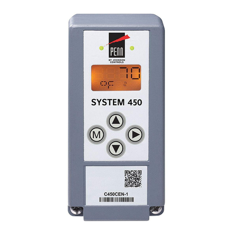
Teknic EF-785 User manual

E
F-785
P
OWER
D
ISTRIBUTION AND
S
AFETY
C
ONTROL
C
ENTER
V
ERSION
1.42
/
A
UGUST
26,
2005
I
NSTALLATION
G
UIDE
T
EKNIC
,
I
NC
F
AX
(585)784-7460
V
OICE
(585)784-7454

T
HIS PAGE INTENTIONALLY LEFT BLANK

E
F-785
O
VERVIEW
......................................................3
eF-785 Benefits.............................................................................. 6
EF-785 Safety Features ..................................................................7
Segmented Machine Support.............................................7
Guard-lock Control ............................................................7
Automatic Safety System Checkout ...................................7
Controlled Stopping Function (ControlPoint™ Only) ..... 8
Integration Steps at a Glance........................................................ 8
I
NTEGRATION
S
TEPS
................................................10
Step 1: Complete a risk assessment and select guard-locks or
interlocks for guarded areas.........................................................10
EN1050 risk assessment ..................................................10
Select Guard-locks or Interlocks (for each guarded
Hazard) ..................................................................................10
Step 2: Select eF-785 configuration options................................ 11
Definitions........................................................................ 11
Step 3: Mount the eF-785 ............................................................21
Important Mounting Dimensions....................................21
Mounting Orientation ..................................................... 22
Cooling............................................................................. 22
Rack Slides ...................................................................... 23
Step 4: Set up the 24VDC Power Distribution............................ 24
Selecting the Power Supplies .......................................... 24
Connecting 24VDC Power supplies (J5)......................... 24
Connecting 24VDC loads (P9-P11) ..................................27
Step 5: Set up DC Motor Power Distribution 48-90VDC .......... 30
Selecting the Power Supplies .......................................... 30
Connecting DC Motor Power Supplies (P6) ................... 30
Connecting the Loads (DC Motor Drives) (P7A, P7B, J8A,
J8B)........................................................................................31
Step 6: Connect AC Powered Motor Drives (P3, J4) .................. 36
Wiring Configurations..................................................................37
Step 7: Connecting other miscellaneous AC loads (J2).............. 38
Step 8: Connect Incoming AC Power.......................................... 39
Incoming Power (P2) ...................................................... 39
Add a Power Disconnect Switch (if required)................. 39
Step 9: Connect the embedded control computer .......................41
CPU, Display and Peripheral Power (JA, JB)..................41
Host Control Connections................................................41
Step 10: Mount and connect the Power/Enable Switch(es)....... 43
Power/Enable Circuits (P14) .......................................... 43
Step 11: Mount and connect the safety control components...... 45
Selecting External Safety Devices ................................... 45
Safety harness for non-segmented machine (P12) ......... 48
Safety harness for segmented machine (P12)................. 49
Auxiliary Safety Connector (p13).................................... 50
Step 12: Optional: Connect ControlPoint™ Components.......... 52
Where does ControlPoint™ technology fit in? ............... 52
R
UNNING A
M
ACHINE WITH THE E
F-785 ..................53
Powering up......................................................................53
T
EKNIC
,
I
NC
F
AX
(585)784-7460
V
OICE
(585)784-7454

Safety alarm check ...........................................................53
Recovering after an E-Stop event ....................................53
Shutting down..................................................................53
Finding and replacing a blown fuse.............................................55
DC Power Over-current Alarm ........................................ 55
AC Control Power Circuit Protection .............................. 55
E
XTENDING THE
S
YSTEM
.........................................57
Controlling External Hazardous Energy ..................................... 57
Example: 3-Phase Power Control................................................ 57
A
PPENDIX
A:
M
EETING THE
EU
M
ACHINERY
D
IRECTIVE FOR
CE
COMPLIANCE
............................58
What is the Machinery Directive (And why is it important even
outside of the EU) ........................................................................58
A
PPENDIX
B:
S
PECIFICATIONS
.................................63
A
PPENDIX
C:
C
ABLE
D
IAGRAMS
...............................64
48–90VDC Load Area to SSt (J8A, J8B) ....................................64
48–90VDC Main Area to SSt (P7A, P7B) ....................................65
48–90VDC Load Area to ISC (J8A, J8B)....................................66
48–90 VDC Main Area to ISC / SSt-ISC (P7A, P7B) ..................67
AC Servo Power Cable, Load Area (J4) .......................................68
AC Servo Power Cable, Main Area (P3).......................................69
SSt-6000, 3000 DC Power Jumper Cable ..................................70
SSt-6000, 3000 AC Input Cable ................................................. 71
Single 24VDC Supply Cable (J5) .................................................72
Dual 24VDC Supply Cable (J5)....................................................73
70 – 90VDC Supply Cable – SSt-EMF75 (P6) ............................74
24VDC Dist. Cable/IOC-APC (P9-P11)...................................... 75
40VDC Power Tap Distribution Cable (P18)...............................76
Front Panel Harness power/enable circuits (P14) ...................... 77
Integration & Testing Cheater Plug safety control ckts (P12).....78
Extension Cheater Plug (P13)......................................................79
Input Power Cable (J2)............................................................... 80
A
PPENDIX
D:
F
IELD
M
ODIFIABLE
O
PTIONS
..............81
Changing the Jumper Settings .................................................... 81
A
PPENDIX
E:
24VDC
S
UPPLY
W
IRING
.....................83
A
PPENDIX
F:
S
AFETY
S
TANDARDS
R
EFERENCE
.....85
Safety standards Referenced in this manual...................85
Miscellaneous safety standards .......................................85
A
PPENDIX
G:
C
ONNECTOR
R
EFERENCE
.................87
Cable Stock.................................................................................. 88
2
V
ERSION
1.42
/
A
UGUST
26,
2005

E
F-785
O
VERVIEW
The eF-785 is Teknic’s patented power distribution and safety control
center, for use in OEM automated machinery. The “eF” designation
stands for “Electrical Foundation”, an appropriate description as the eF-
785 consolidates nearly all of the required safety, power management
and distribution functions required in an automated machine into one
easy-to-integrate box.
F6
24
VDC
Ckt. 3
10A Max. 40
VDC
ControlPoint
TM
24
VDC
Safety
F7 F8 F10F9
DC Servo Main
15A Max.
DC Servo Option
15A Max.
CB2 CB3
Status
24
VDC
Ckt. 2
10A Max.
24
VDC
Ckt. 1
10A Max.
SAFETY ALARM
Do not operate or service
machine if sounding
eFoundation- Power Distribution & Safety Control Center
CB1, UL489 Rated Input Breaker
10,000A Interrupting
When installed according to the
accompanying instructions this unit meets:
- UL 61010-1 2nd Edition
- EN 61010
- EN 60204
- EN 954-1 (Class 2)
- Semi S2
- EN 61326
Teknic, Inc.
F
e
785
CUS
CM
I
N
T
E
R
T
E
K
L
I
S
T
E
D
20
20
eF-785 Power Distribution and Safety Center (front panel pictured)
Experienced machine designers know that successfully complying
with the myriad of complicated, often ambiguous compliance standards,
means spending laborious hours working on the electrical distribution,
control, and safety circuits before compliance testing can even begin.
Purchase the eF-785, and most of that work is already done. The eF-785
provides all of the critical “foundation” functions you need in a pre-
tested, value priced, off-the-shelf assembly. Though these functions do
not, typically, provide the OEM with a huge differential advantage, the
eF-785, properly implemented, will reduce your engineering burden,
assure that safety and compliance standards are met with a minimum of
hassle, and speed your product to market.
Time after time our field engineers have come back to report a
product rollout hampered or delayed by oversights and last minute
testing and rework of these critical circuits. As a direct result of these
observations, Teknic set out to build a better solution for our OEM
customers. The eF-785 is that solution. It’s the all-in-one answer to your
machine’s power distribution, safety and control requirements. It’s
economical, easy to integrate, and can greatly improve your machine
production time. Why reinvent the wheel when you can join a growing
number of customers who call the eF-785 Compliance in a Box™.
eF-785
I
NSTALLATION
M
ANUAL
3
T
EKNIC
,
I
NC
F
AX
(585)784-7460
V
OICE
(585)784-7454

4
V
ERSION
1.42
/
A
UGUST
26,
2005
F6
24
VDC
Ckt. 3
10A Max. 40
VDC
ControlPoint
TM
24
VDC
Safety
F7 F8 F10F9
DC Servo Main
15A Max.
DC Servo Option
15A Max.
CB2 CB3
Status
24
VDC
Ckt. 2
10A Max.
24
VDC
Ckt. 1
10A Max.
SAFETY ALARM
Do not operate or service
machine if sounding
eFoundation- Power Distribution & Safety Control Center
CB1, UL489 Rated Input Breaker
10,000A Interrupting
When installed according to the
accompanying instructions this unit meets:
- UL 508
- EN 61010
- EN 60204
- EN 954-1 (Class 2)
- Semi S2
- EN 50081-2
- EN 50082-2
Teknic, Inc.
F
e
785
2020
Control Computer
Door Interlocks
(with or without locks)
Controlled / Protected Power Distribution
On/Off
Reset
Disconnect
Switch
EMO
Switch
24VDC Dist.
(6 Circuits)
Hazardous AC
AC Servo Dist.
(2 Circuits)
DC Servo Dist.
(4 Circuits)
Power
Supplies
AC
ACControl
DC
eF-785 Simplified Context Diagram
As shown in the context diagram above, the eF-785 manages a number of
critical functions in your machine including:
•
•
•
•
•
•
•
Power control
Power sequencing
Safety disconnect
Over-current protection
Safety guard lock control/interlocks
Regenerated power dissipation
Conducted EMI filtering
In fact, creating a complete machine power system based on the eF-
785 requires only a comparatively small amount of work. And, if you
follow the installation instructions in this manual, your machine’s power
control system will meet US, European and world standards for electrical
and machine safety, including EN 954-1, EN 60204, EN 61010 and
Semiconductor safety standards SEMI S8 and S2.
The eF-785 can easily manage the power control requirements of a
“two-area” (segmented) machine. This type of machine features a Main
Area and an operator accessible Load/Unload Area, each under separate
control. The eF-785 allows a machine operator to safely disable
hazardous power to the Load/Unload Area while the Main Area of the
machine continues core processing operations. Your customers will
appreciate the greater machine throughput this affords them.
The eF-785’s power-disconnect and safety control is fully compliant
with EN-954-1 (required for compliance with the CE Machinery
Directive). This hazardous power-disconnect is fully single fault tolerant
to component and machine wiring faults and is monitored to detect any

single fault. You won’t need any additional safety control components
(safety relays or controllers) when using the eF-785.
JA
Host Power
JB
Host Power
P3
Main AC
Motor Power Load AC
Motor Power
J4
F1, F2
Host Pwr. 8A Max
P14
P13
P12
Safety Harness Safety Control Ext.
IEEE-1284 Host Port
J17
P18
40V Net Out Net In
RED BLK
100-125/200-240
VAC~ 20A, 50-60Hz
P2
P9 A,B
24VDC
Ckt. 1
P10 A,B
24VDC
Ckt. 2
J8A J8B
Option DC Motor Pwr.
90VDC Max.
Main DC Motor Pwr.
90VDC Max.
P7A P7B
DC Servo
Supply
24VDC
Supply
Hazardous
AC Out
J2 J5 P6
P11 A,B
24VDC
Ckt. 3
SA
USB
P15 P16
115V
DC
AC
48-90VDC
Power Supply
(2 max)
DC
AC
24VDC
Power Supply
(2 max)
DC Motor Drives (4 circuits total)
24VDC Devices (6 circuits total)
Guardlocks
AC Motor Drives
Load Area
Main Area
Main Area
Load Area
Interlocks or Guardlocks
AC power
to Control PC
AC power
to Control PC
E-Stop
AC Power
to miscellaneous
(hazardous) devices
Power/Enable
AC Power Source
Control PC
Main Area
(2 circuits)
Load Area
(2 circuits)
Hooking up the eF-785
eF-785
I
NSTALLATION
M
ANUAL
5
T
EKNIC
,
I
NC
F
AX
(585)784-7460
V
OICE
(585)784-7454

6
V
ERSION
1.42
/
A
UGUST
26,
2005
...Plus, if you need to control more than 4KVA of power, use 3-
phase power, or if your machine has other hazards you’d like the eF-785
to manage, you can extend the system’s capabilities by utilizing the eF-
785’s safety control and feedback signals. These signals are readily
available on the rear panel connector, P13. Learn how to do this in the
Extending the System section of the manual.
Another handy feature, the Soft Shutdown, allows the operator to
power up the control computer from the machine’s front panel On/Off
switch and automatically shut off power to the machine after the control
computer has completed its shutdown process.
24 VDC
Fault-Tolerant
Hazardous Power
Control
Control Computer
Disconnect
Feedback
Contactor
Control
Command
& Monitoring
Control
Data
Control System
Power
Safety
Control
Power
AC Power to
Hazardous Loads
24VDC Power to
Non-Hazardous
Sensors,
Actuators, Valves
Lamps, etc.
48-90VDC Power
to Hazardous
Loads
Main
Breaker
Regeneration and
Power Dump Loads
Front Panel
Power Control
Over-current
Annunciation
Safety Fault
Alarm
Servo or Stepper Motors
Connected to Mechanical
Hazards
eF-785
Power Hub &
Safety Manager
Optional
ControlPoint
Network Hub
E-Stop
Switch(es)
Guard Interlock
Switch(es)
Guard Solenoid
Lock{s)
AC Power
Distribution Hub
24 VDC
On-Off Control
&
Safety Supply
Safety Control
Expansion Signals
EMI
FiItering
Hazardous Power
Disconnect and Clamp
Motor
Drive
Motor
Drive
External Power
Supplies
Motor
Drive
Preemptive
E-stop signal
48-90 VDC
AC Power
DC Power
Control Signals
Optional ControlPoint Network
Control
INT
P
Power
Sequencing &
Monitoring
Main
Disconnect
DC Power
Distribution Hub with
Over-current
Protection
Safety and Compliance highlights in the eF-785
E
F-785
B
ENEFITS
zSignificantly reduces electrical system design, integration and
debug effort, reducing time to market
zEases wiring requirements, lowering total machine costs
zIntegrates numerous functions in one compact enclosure,
supporting a smaller machine footprint
zSpeeds compliance inspection and testing of a machine for:
oEMC (electromagnetic compatibility),
oMachine Safety (mechanical hazards)
oElectrical Safety (shock and fire hazards)

zSignificantly reduces the risk of failure during machine testing,
making your product launch more predictable
zFeatures a monitoring function to help pinpoint wiring errors in
the safety control system during integration and assembly
zAllows for controlled motor stopping during an Emergency Stop,
minimizing wear and tear on the machine
zVirtually eliminates intermittent connections within e-stop
switches and contactors via proprietary wiring
EF-785
S
AFETY
F
EATURES
S
EGMENTED
M
ACHINE
S
UPPORT
The eF-785 can be configured so that AC power to mechanical hazards is
controlled independently in two different functional areas of a machine.
This means that an operator can easily power down the mechanical
hazards in one part of a machine (Load Area) while the Main Area of the
machine continues to process material, samples, etc, allowing an
operator to feed and retrieve material from the machine while it
continues to do useful work. This can result in a significant,
demonstrable throughput advantage on many automated machines.
G
UARD
-
LOCK
C
ONTROL
The eF-785 has specific outputs that control any installed guard-locks
that open guard doors when hazardous power is removed from a given
machine area. These guard-locks are controlled by user software and
electromagnetic logic control. To open guardlocks, two things must
occur: 1) the user software must issue an “open guardlock” request and 2)
removal of hazardous power must be confirmed by the electromagnetic
logic control.
A
UTOMATIC
S
AFETY
S
YSTEM
C
HECKOUT
The monitoring systems within the eF-785 perform several functions:
they monitor the e-stop and interlock switches (and wiring) for faults,
continuously check the contactors for the proper electromagnetic status
of the hazardous power and guard-lock power. In the event that the
monitoring system detects any errors during operation, it reinforces the
removal of power (which is enforced by the electromagnetic logic control)
and reports the errors to the host computer.
The eF-785 has two important safety diagnostic functions. One
function forces the user to perform a safety test of the e-stop and
interlock switches at each power-up cycle. Periodic checking of these
switches is required by EN 954-1 and this mechanism makes the
procedure automatic. This function removes the requirement for writing
and enforcing periodic inspection procedures and attaching placards or
writing custom software to instruct operators. This function can be
disabled during machine development.
The eF-785 firmware also maintains data on the complete state of the
safety control system just before and after a fault is detected. This
information can help pinpoint the fault to a few possible failures,
speeding up root cause identification.
eF-785
I
NSTALLATION
M
ANUAL
7
T
EKNIC
,
I
NC
F
AX
(585)784-7460
V
OICE
(585)784-7454

C
ONTROLLED
S
TOPPING
F
UNCTION
(C
ONTROL
P
OINT
™
O
NLY
)
The eF-785 can act as a network hub for connecting Teknic’s open
ControlPoint™ networked motion and I/O control nodes. These nodes
can control servomotor or stepper motor axes. When using the eF-785
with ControlPoint™ components in charge of the motion control,
controlled stopping of the motion axes within a machine can be
automatically initiated by the eF-785 when a safety shutdown occurs.
This, combined with the eF-785 ’s hazardous power disconnect delay
function, forces the axes to a smooth controlled stop (in the fraction of
the second before power removal) during an E-Stop, interlock open and
most other safety shutdown events. This typically saves the material in
process, reduces wear and tear on the machine, and generally increases
the perceived quality of the machine by the customer.
I
NTEGRATION
S
TEPS AT A
G
LANCE
Create a complete power & safety system for your machine
using the eF-785 by following these simple steps:
1. Complete a risk assessment of your machine hazards, and then
select guard-locks or interlocks for guarded areas.
2. Select the eF-785 configuration options that fit your machine
requirements.
3. Mount the eF-785.
4. Select and connect the external 24VDC power supplies and devices
to the eF-785. Example cables are shown in Appendix C of this
manual.
5. Select and connect the external DC motor power supplies and DC
motors to the eF-785. Example cables are shown in Appendix C of
this manual.
6. Connect AC powered servo drives. Example cables are shown in
Appendix C of this manual.
7. Connect any other AC loads.
8. Connect incoming AC power, and if required, an incoming power
disconnect switch.
9. Connect the embedded control computer to the eF-785 using off-
the-shelf cables (modular power cord, USB cable, IEEE-1284
cable).
10. Mount the machine’s on-off switch(es) and connect them to the eF-
785. An example cable including recommended switches is shown
in Appendix C of this manual.
11. Mount the safety system components (e-stop switches, interlock
switches and/or guard locks) and connect them to the eF-785. You
will find recommended devices for all of these components in this
manual.
12. Optional: Connect Teknic ControlPoint™ motion and I/O
components via standard Category 5 patch cables.
This manual contains all of the instructions you’ll need to complete each
of these tasks quickly with a minimum of research, while meeting all of
the required safety standards.
8
V
ERSION
1.42
/
A
UGUST
26,
2005

Within the manual you’ll find many detailed drawings, illustrations
and schematics created with you, the OEM Machine Manufacturer, in
mind. Our objective is to provide you with all of the information you need
to successfully visualize, integrate and install the eF-785 in your
machine. To that end we’ve included a complete set of cable drawings,
each with a comprehensive bill of materials. Additionally, we’ve
researched, tested and recommended a number of critical components
including switches, interlocks and guard-locks.
eF-785
I
NSTALLATION
M
ANUAL
9
T
EKNIC
,
I
NC
F
AX
(585)784-7460
V
OICE
(585)784-7454

I
NTEGRATION
S
TEPS
S
TEP
1:
C
OMPLETE A RISK ASSESSMENT AND SELECT GUARD
-
LOCKS OR INTERLOCKS FOR GUARDED AREAS
EN1050
RISK ASSESSMENT
For each risk in your machine you must perform a risk assessment
according to the EN 1050 standard. Naturally, you should acquire a copy
of the EN 1050 standard and follow it to accomplish this. The results of
this risk assessment will help you determine the appropriate level of
safety control system required per EN 954-1 (levels B, 1, 2, 3 or 4) for
each hazard. The eF-785 can meet levels B,1,2, and 3. Therefore, in order
to use the eF-785 as a “stand-alone” safety control center, none of the
hazards in your machine can exceed EN 954-1 level 3 requirements.1
S
ELECT
G
UARD
-
LOCKS OR
I
NTERLOCKS
(
FOR EACH GUARDED
H
AZARD
)
IMPORTANT: You should read Appendix A of this manual:
“Meeting the EU Machinery Directive for CE Compliance” to
ensure your machine meets certain requirements. If your machine meets
the assumptions described in Appendix A, you can follow the rules below
for selecting between interlock switches (which simply indicate the
open/closed state of a guard) and guard-lock switches (which are
interlock switches with physical solenoid-driven locking devices):
You can use interlock switches (without locks) on guards in the Main
area of your machine when:
a. The hazards are such that the EN 954-1 assessment concludes that
they require a level B, 1, or 2 safety control system,
or
b. when the guards are clearly marked as containing hazards behind
them and the guard can only be opened with a tool or key.
Guard-locks must be used if the hazards are such that the EN 954-1
assessment concludes that they require a level 3 safety control system.
Guard-locks may be required in some areas while only interlocks may be
required in others. See Appendix A for more details.
In the Load area of your machine, guard-locks (interlock switches
with power-off locks) must always be used, regardless of the types of
hazards.
If you are unsure where to use guard-locks vs. interlocks you can
safely elect to use guard-locks in all positions as they offer superior safety
qualities. This will provide you with an additional method of control over
user access, often advantageous for other operational reasons.
1It’s usually possible to extend the eF-785 with external components to meet EN-954
level 4 compliance but that topic is beyond the scope of this manual. It’s often easier to
reduce the hazards in the machine to lower the required level of the safety control
system, by eliminating pinch points, having mechanical interlocks with guards, etc.
10
V
ERSION
1.42
/
A
UGUST
26,
2005

S
TEP
2:
S
ELECT E
F-785
CONFIGURATION OPTIONS
Now it’s time to specify your eF-785. For this task you should know a few
things:
1. Your machine’s operational and power requirements
2. The definitions of a few key terms used in this section
3. The available options from which to choose
4. How to “build” a valid eF-785 part number
Assuming that your machine requirements are known, we will
proceed into an explanation of the definitions, available options, and how
those options are expressed as a part number. The objective here is to
give you the information necessary to understand, specify, and order the
eF-785 that will best meet your project requirements.
D
EFINITIONS
Please read the following definitions before proceeding:
Segmented Machine A machine that has more than one work
processing area. A segmented machine is one
that is designed to allow an operator to safely
load or unload raw or finished product in one
(Load) area while main processing activities
continue undisturbed in another (Main) area
under separate power and safety control.
Main Area The main functional area of an automated
machine. The Main Area is typically where the
core processing work of the machine is
performed. All machines have a Main Area;
whereas, segmented machines may have both a
Main and a Load area.
Load Area A specific section of a segmented machine,
separate from the Main Area. The Load Area is
typically a secondary area of a segmented
machine such as an operator Load/unload
access area. It is often advantageous from both
a machine throughput and safety standpoint to
operate the Load Area under separate power
and safety control from the Main Area. The eF-
785 is designed to support this.
eF-785
I
NSTALLATION
M
ANUAL
11
T
EKNIC
,
I
NC
F
AX
(585)784-7460
V
OICE
(585)784-7454

12
V
ERSION
1.42
/
A
UGUST
26,
2005
P
OWER
C
ONTROL
O
PTIONS
The eF-785 offers you several options as to how you distribute power to
AC and DC servo or stepper motor drives in your automated machine.
Not only can you power multiple AC and/or DC motor drives
simultaneously through the eF-785, but you can control the flow of power
to these drives in two separate areas of your machine (Main and Load
Area) under separate safety and power control. This flexibility provides
you with an easy way to create a segmented machine (defined on the
previous page) that offers several advantages in terms of safety and
throughput to your end user.
In this section we will describe the available power control options for
the eF-785, illustrating each with a small schematic diagram. Below is a
brief table summarizing the available options and the appropriate code to
use when ordering.
Main Area Load Area Option Code
DC powered drives None DN
AC or [AC and DC]
powered drives None AN
DC powered drives DC powered drives DD
AC or [AC and DC]
powered drives DC powered drives AD
AC or [AC and DC]
powered drives
AC or [AC and DC]
powered drives AA
Single-area MachineSegmented Machine
eF-785 Motor Drive Power Options

AA- This is the most versatile of the 5 power control options. The AA
model leaves all of your design options open. It supports both AC and DC
powered motor drives in the Main Area, and both AC and DC powered
motor drives in the Load Area. Example part number:
EF-785-AAxx-xxx-x
J2
P3
P7B
P7A
J8B
J8A
J4
P6
Main Load
Safety Control
48-90VDC
Supply
CB1
P2
Interlock
switches
E-Stop
switches
To general hazardous
loads
To Main Area
AC Motor Drives
To Load Area
AC Motor Drives
To Main Area
DC Motor Drives
To Load Area
DC Motor Drives
AC
DC
AA Configuration
Door locks
Simplified power flow schematic-AA
AD- The AD model supports AC and DC powered motor drives in the
Main Area, and DC powered motor drives in the Load Area. Example part
number: EF-785-ADxx-xxx-x.
J2
P3
P7B
P7A
J8B
J8A
P6
Main Load
Safety Control
48-90VDC
Supply
CB1
P2
Interlock
switches
E-Stop
switches
To general hazardous
loads
To Main Area
AC Motor Drives
To Main Area
DC Motor Drives
To Load Area
DC Motor Drives
AC
DC
AD Configuration
Door locks
Simplified power flow schematic-AD
eF-785
I
NSTALLATION
M
ANUAL
13
T
EKNIC
,
I
NC
F
AX
(585)784-7460
V
OICE
(585)784-7454

14
V
ERSION
1.42
/
A
UGUST
26,
2005
AN- The AN configuration supports AC and DC powered motor drives
in the Main Area, but no Load Area drives. In the AN configuration, the
J8 circuits, normally reserved for Load Area functionality, may be used
as additional Main Area circuits. Example part number:
EF-785-ANxx-xxx-x.
J2
P3
P7B
P7A
J8B*
J8A*
P6
Main Load
Safety Control
48-90VDC
Supply
CB1
P2
Interlock
switches
E-Stop
switches
To general hazardous
loads
To Main Area
AC Motor Drives
To Main Area
DC Motor Drives
AC
DC
AN Configuration
Door locks
*see text
Simplified power flow schematic-AN
DD- The DD configuration supports DC powered motor drives in the
Main area and DC powered motor drives in the Load area. Example part
number EF-785-DDxx-xxx-x.
J2
P7B
P7A
J8B
J8A
P6
Main Load
Safety Control
48-90VDC
Supply
CB1
P2
Interlock
switches
E-Stop
switches
To general hazardous
loads
To Main Area
DC Motor Drives
To Load Area
DC Motor Drives
AC
DC
DD Configuration
Door locks
Simplified power flow schematic-DD

DN- The DN configuration supports DC powered motor drives in the
Main Area only, but no Load Area. In the DN configuration, the J8
circuits, normally reserved for Load area functionality, may be used as
additional Main Area circuits. Example part number:
EF-785-DNxx-xxx-x.
J2
P7B
P7A
J8B*
J8A*
P6
Main Load
Safety Control
48-90VDC
Supply
CB1
P2
Interlock
switches
E-Stop
switches
To general hazardous
loads
To Main Area
DC Motor Drives
AC
DC
DN Configuration
Door locks
* see text
Simplified power flow schematic-DN
PURCHASING A UNIT FOR DEVELOPMENT
For the purposes of machine design and development, Teknic
recommends that you initially order the AA configuration. This leaves
your design options open (the AA configuration can do the work of any
of the other four power configurations). Once your machine design is
stable, order only the options you need.
EMI
FILTERING
O
PTIONS
The eF-785 offers two available EMI filtering options, two-stage (D) and
four-stage (Q).
T
WO
-S
TAGE
(D
UAL
)
F
ILTERING
The basic level of EMI filtering offered for the eF-785 is two-stage (Dual)
filtering indicated by the letter Din the position shown above. The 2-
stage option is standard in configurations where only DC powered motor
drives are present in the machine (i.e. power control configurations DD
or DN). This (lesser) magnitude of filtering is usually sufficient for
machines in which there are no AC powered motor drives present.
F
OUR
-S
TAGE
(Q
UAD
)
F
ILTERING
Quad or four-stage filtering is specified by the letter Q. Four-stage
filtering comes standard on all eF-785s configured for AC powered motor
drives (i.e. power configurations AA, AD, and AN). With this level of
filtering, your machine can meet EN 50081-2 and EN 50082-2 for
emissions and susceptibility without individual line filters for each servo
drive (typically a notable cost savings).
eF-785
I
NSTALLATION
M
ANUAL
15
T
EKNIC
,
I
NC
F
AX
(585)784-7460
V
OICE
(585)784-7454

16
V
ERSION
1.42
/
A
UGUST
26,
2005
Optionally, 4-stage filtering may be added as an upgrade to DC motor
drive configurations if additional EMI filtering is required.
CP
N
ETWORK
H
UB
O
PTIONS
Using ControlPoint™ components can greatly simplify wiring
complexity, reduce integration effort, and decrease the number of
assemblies in your machine. Ultimately this will save money and help
reduce errors in design and implementation. ControlPoint™ also
provides a controlled shutdown function for all connected motor drives
when an E-Stop is detected or door interlocks are opened. This works
seamlessly with the optional eF-785 Power-Off Delay to provide very
controlled machine shutdowns.
This position of the eF-785 part number indicates the presence (C) or
absence (X) of the optional Teknic ControlPoint™ network hub and
integrated 40V network power supply. If you are currently using Teknic’s
ControlPoint™ components, you’ll quickly realize the benefits of
incorporating the CP network hub and 40V network power supply into
your eF-785.
If your design does not include the ControlPoint™ hub with 40VDC
network power supply, order your eF-785 with an Xin the indicated
position. With or without ControlPoint™ options, the eF-785 provides
excellent power distribution and safety control functionality.
P
OWER
-
OFF DELAY
O
PTIONS
(M
AIN
)
The eF-785 offers you some options as to how quickly hazardous power is
removed from the Main Area of your machine. Q: When can this option
be valuable? A: In cases where the sudden removal of power from a
motor axis could cause significant (read expensive) damage to the
machine, its payload, or both.
The safety guidelines outlined by EN 954-1 allow for a power-off delay
as long as certain criteria are met, and the eF-785 meets these guidelines.
The delay should be selected to allow for a controlled stop of the relevant
motor axes in the event of an E-stop event. The delay can also be
independently configured for the Load/Unload Area, if the machine is
segmented. Available options and codes are listed below.
NNo Delay Required
FFast Delay (150mS) - For smaller axes or axes where high rates of
deceleration are tolerable.
SSlow Delay (450mS) - For larger axes or axes where more time is
required to complete a controlled removal of power.

P
OWER
-
OFF
-
DELAY
O
PTIONS
(L
OAD
)
The power-off-delay in the Load Area is configured in the same way as
described in the Main Area. If there is no Load Area select code X in the
F-785 part number where indicated.
NNo delay required
FFast delay (150 mS) - For smaller axes or axes where high rates of
deceleration are tolerable.
SSlow Delay (450mS) - For larger axes or axes where more testtime is
required.
XNot applicable. No Load Area designated.
S
UPPLEMENTARY
O
PTIONS
C
ONFIGURING
S
UPPLEMENTARY
O
PTIONS
The Soft Shutdown and Post E-Stop Enable features comprise the eF-785
Supplementary Options. Each of these two options is factory
preconfigured to your specification, but can be reconfigured by
repositioning one or two hardware jumpers. Below is a list of the 4
possible Supplementary Option configurations available with the eF-785.
BHost Soft Shutdown disabled; Post E-Stop Enable bypassed
CHost Soft Shutdown enabled; Post E-Stop Enable bypassed
DHost Soft Shutdown disabled; Post E-Stop Enable required
EHost Soft Shutdown enabled; Post E-Stop Enable required
S
OFT
S
HUTDOWN
F
EATURE
The soft shutdown feature allows you to power off your machine by
shutting down the host computer. This feature is user configurable by
installing (or removing) an internal hardware jumper. See the appendix
for details.
Example scenario of a system with Soft Shutdown enabled:
Power up with Soft Shutdown enabled - An operator initiates the
machine power-up cycle by pressing the machine’s front panel “on”
button (which is wired into the eF-785). The machine powers up and the
eF-785 sends AC power to the host computer which then powers up as
well. Immediately, the PC sends a signal, via USB connection, to the
eF-785, creating a feedback loop. And, as long as the USB signal is
present at the eF-785’s USB port, the system remains powered. Note: to
use this feature, the BIOS on the control PC must be configured to power
up the PC when AC power is detected.
eF-785
I
NSTALLATION
M
ANUAL
17
T
EKNIC
,
I
NC
F
AX
(585)784-7460
V
OICE
(585)784-7454

Power down with Soft Shutdown enabled – When the operator
powers down the host PC, the USB signal to the eF-785 turns off. When
the eF-785 no longer detects the USB signal, it shuts down the entire
machine.
Note: When Soft Shutdown is enabled, pulling the USB cord out of the
eF-785 will have the same effect as turning the eF-785 off via the power
switch.
Follow these steps to provide Soft Shutdown functionality in
your machine
1) Select one of the two options that feature host Soft Shutdown
enabled (see the Configuring Supplementary Options section
below).
2) Configure the host PC BIOS to power up the PC when AC power is
present.
3) Connect the PC to the eF-785 with a standard USB cable.
P
OST
E-S
TOP
E
NABLE FUNCTION
The Post E-Stop Enable function is an extra layer of protection that
serves to provide independent confirmation from the operator that it is
safe to resume normal machine operation after an Emergency Stop (E-
Stop) has occurred.
Consider a typical machine that has several E-Stop buttons on it.
When the machine operator observes that a dangerous condition exists,
he would actuate (i.e. “hit”) the nearest E-Stop button on the machine,
terminating machine operations as a result. When the Post E-Stop
Enable function in the eF-785 is functional, the operator must reset the
E-Stop button to its normal ‘run’ position, and then press the machine’s
On/Enable button in order for the machine to resume normal operations.
Note: The operator should always follow safe machine operating
procedures and return to a safe operating position prior to any machine
restart. If operation were to immediately resume after an E-Stop button
was restored to the ‘run’ position, an undesirable, potentially dangerous
operational condition could occur. Always know and follow your
machine’s safe operation guidelines.
Having the Post E-Stop Enable feature enabled is especially important
in cases where it is possible for an operator (or parts of an operator) to be
inside a machine while the interlocks are closed.
For general safety and compliance requirements, Teknic recommends
that you configure your eF-785 with the Post E-Stop Enable feature
activated (options Dand E).
The Post E-Stop Enable feature satisfies the ‘Manual Reset’ step
required by EN 954-1. As previously stated, the machine safety design
engineer should perform a complete safety assessment prior to selling
machines with this function disabled. Read EN 954-1 carefully to
decide if your machine can operate with the Post E-Stop
Enable function bypassed.
During the engineering design and development phases, the Post E-
stop Enable function can be inconvenient. By disabling the Post E-Stop
Enable function, machine operation can resume immediately after an
actuated E-Stop button has been restored to its normal “Run” position,
assuming that the system software is configured to allow this and the
18
V
ERSION
1.42
/
A
UGUST
26,
2005
Table of contents
