ZETRON 4000 Sereis User manual

Series 4000 Communication Control
System Operation
Version 5.6
025-9535L

©Zetron, Inc. All rights reserved. This publication is protected by copyright; information in this document is subject to
change without notice. Zetron and the Zetron logo are registered trademarks of Zetron, Inc. Other company names and
product names may be the trademarks or registered trademarks of their respective owners. This publication may not be
reproduced, translated, or altered, in whole or in part, without prior written consent from Zetron, Inc.
Software License
The Zetron software described in this manual is subject to the terms and conditions of Zetron's Software License Agreement,
a copy of which is contained on the product distribution media or otherwise provided or presented to buyer. Installation and/
or use of the Zetron software constitutes acceptance of Zetron's Software License Agreement.
Limited Warranty
Buyer assumes responsibility for the selection of the Products to achieve buyer's or its customer's intended results obtained
from the Products. If buyer has provided Zetron with any requirements, specifications or drawings, or if Zetron provides
buyer with such materials, such materials are provided solely for buyer's convenience and shall not be binding on Zetron
unless agreed in writing by the President of Zetron. ZETRON DOES NOT WARRANT THAT THE PRODUCTS OR ITS
CUSTOMER'S REQUIREMENTS OR SPECIFICATIONS OR THAT OPERATION OF THE PRODUCTS WILL BE
UNINTERRUPTED OR ERROR FREE. SUBJECT TO THE LIMITATIONS SET FORTH BELOW, Zetron warrants that all
Zetron Products and Zetron Accessories will be free from material defects in material and workmanship for one year from
date of shipment (except where indicated otherwise in the Zetron Price Book). For buyer's convenience, Zetron may purchase
and supply additional items manufactured by others. In these cases, although Zetron's warranty does not apply, buyer shall be
the beneficiary of any applicable third party manufacturer's warranties, subject to the limitations therein. Zetron's warranty
covers parts and Zetron factory labor. Buyer must provide written notice to Zetron within the warranty period of any defect. If
the defect is not the result of improper or excessive use, or improper service, maintenance or installation, and if the Zetron
Products or Zetron Accessories have not been otherwise damaged or modified after shipment, AS ZETRON'S SOLE AND
EXCLUSIVE LIABILITY AND BUYER'S SOLE AND EXCLUSIVE REMEDY, Zetron shall either replace or repair the
defective parts, replace the Zetron Products or Zetron Accessories or refund the purchase price, at Zetron's option, after return
of such items by buyer to Zetron. Shipment shall be paid for by the buyer. No credit shall be allowed for work performed by
the buyer. Zetron Products or Zetron Accessories which are not defective shall be returned at buyer's expense, and testing and
handling expense shall be borne by buyer. Out-of-warranty repairs will be invoiced at the then - current Zetron hourly rate
plus the cost of needed components. THE FOREGOING WARRANTY AND THE THIRD PARTY MANUFACTURER'S
WARRANTIES, IF ANY, ARE IN LIEU OF ANY AND ALL OTHER WARRANTIES EXPRESSED, IMPLIED OR
ARISING UNDER LAW, INCLUDING, BUT NOT LIMITED TO, THE IMPLIED WARRANTIES OF
MERCHANTABILITY, NON-INFRINGEMENT AND FITNESS FOR A PARTICULAR PURPOSE.
Limitation of Liability
Zetron makes no representation with respect to the contents of this document and/or the contents, performance, and function
of any accompanying software.
ZETRON SHALL NOT UNDER ANY CIRCUMSTANCES BE LIABLE TO BUYER OR ANY THIRD PARTY FOR ANY
INCIDENTAL, SPECIAL, CONSEQUENTIAL OR INDIRECT LOSS OR DAMAGE ARISING OUT OF OR
CONNECTED WITH BUYER'S PURCHASE OR USE OF PRODUCTS OR SERVICES, INCLUDING WITHOUT
LIMITATION, LOSS OF USE, LOSS OR ALTERATION OF DATA, DELAYS, LOST PROFITS OR SAVINGS, EVEN IF
ZETRON HAS BEEN ADVISED OF THE POSSIBILITY OF SUCH DAMAGES AND EVEN IF THE LIMITED
REMEDY ABOVE IS FOUND TO FAIL OF ITS ESSENTIAL PURPOSE. IN NO EVENT SHALL ZETRON'S
LIABILITY (WHETHER FOR NEGLIGENCE OR OTHER TORT, IN CONTRACT OR OTHERWISE) EXCEED THE
PRICE PAID TO ZETRON FOR THE PRODUCTS.
IP networks by their nature are subject to a number of limitations, such as security, reliability, and performance. Anyone using
non-dedicated IP networks, such as shared WANs or the Internet, to connect to any Zetron Products or systems should
consider and is responsible for these limitations.

3
Regulatory Compliance
FCC Class A User Information
This equipment has been tested and found to comply with the limits for a Class A digital device, pursuant to Part 15 of the
FCC Rules. These limits are designed to provide reasonable protection against harmful interference when the equipment is
operated in a commercial environment. This equipment generates, uses, and can radiate radio frequency energy and, if not
installed and used in accordance with the instruction manual, may cause harmful interference to radio communications.
Operation of this equipment in a residential area is likely to cause harmful interference in which case the user will be required
to correct the interference at his own expense.
Regulatory Compliance Markings
When required these products are provided with the following Product Certification Markings:
• FCC markings
• FCC Part 68 (USA)
• CS-03(Canada)
EMC Compliance
• FCC Part 15 - Radiated & Conducted Emissions (USA)
• ICES-003 - Radiated & Conducted Emissions (Canada)
Telecommunications Compliance
• FCC Part 68 (USA)
• CS-03 (Canada)
Products and batteries with the symbol (crossed-out
wheeled bin) cannot be disposed as household
waste. Old electrical and electronic equipment and
batteries should be recycled at a facility capable of
handling these items and their waste byproducts.
Contact your local authority for details in locating a
recycle facility nearest to you.
Proper recycling and waste disposal will help
conserve resources whilst preventing detrimental
effects on our health and the environment.
Notice: The sign “Pb” below the symbol for
batteries indicates that this battery contains lead.
Information on Disposal of Old Electrical and Electronic Equipment and
Batteries (applicable for EU countries that have adopted separate waste
collection systems)

4025-9535L
Safety Summary
• Follow all warnings and instructions marked on the equipment or included in documentation.
• Only technically qualified service personnel are permitted to install or service the equipment.
• Be aware of and avoid contact with areas subject to high voltage or amperage. Because some components
can store dangerous charges even after power is disconnected, always discharge components before
touching.
• Never insert objects of any kind through openings in the equipment. Conductive foreign objects could
produce a short circuit that could cause fire, electrical shock, or equipment damage.
• Remove rings, watches, and other metallic objects from your body before opening equipment. These
could be electrical shock or burn hazards.
• Ensure that a proper electrostatic discharge device is used, to prevent damage to electronic components.
• Do not attempt internal service of equipment unless another person, capable of rendering aid and
resuscitation, is present.
• Do not work near rotating fans unless absolutely necessary. Exercise caution to prevent fans from taking
in foreign objects, including hair, clothing, and loose objects.
• Use care when moving equipment, especially rack-mounted modules, which could become unstable.
Certain items may be heavy. Use proper care when lifting.
Added for Rev K, 6 March 2013
•UpdatedSeries 4000 System Manuals on page 15 for SDC.
•UpdatedReceiving a Call on page 95 to reorganize screen shots.
•AddedSprint Direct Connect (SDC) Functions on page 100.
•AddedSprint Direct Connect (SDC) Operation on page 105.
•UpdatedGeneral Glossary on page 150 for SDC.
Added for Rev K.1, 15 April 2013
•AddedEnding the Call on page 100 and 109.
Change List for Rev L, December 2015
• Removed references to the obsolete Quad Patch Card option from the description of the
Channel Status Regions, specifically the Channel Patch Status on page 56 and Performing a
Group Patch (Patch Groups) on page 64
Warning! For your safety and the protection of the equipment, observe these
precautions when installing or servicing Zetron equipment:
STOP

Contents
5
Contents
Introduction. . . . . . . . . . . . . . . . . . . . . . . . . . . . . . . . . . . . . . . . . . . . . . . . . . . . . . . 9
Button-Based Consoles . . . . . . . . . . . . . . . . . . . . . . . . . . . . . . . . . . . . . . . . . . . . . . . . . . . . . . . . . 9
IntegratorRD Workstations . . . . . . . . . . . . . . . . . . . . . . . . . . . . . . . . . . . . . . . . . . . . . . . . . . . . . 13
Manuals . . . . . . . . . . . . . . . . . . . . . . . . . . . . . . . . . . . . . . . . . . . . . . . . . . . . . . . . . . . . . . . . . . . . 15
Operating Button-Based Consoles. . . . . . . . . . . . . . . . . . . . . . . . . . . . . . . . . . . 17
Console Panel Overview . . . . . . . . . . . . . . . . . . . . . . . . . . . . . . . . . . . . . . . . . . . . . . . . . . . . . . . 17
Model 4018 Desktop Console . . . . . . . . . . . . . . . . . . . . . . . . . . . . . . . . . . . . . . . . . . . . . . . . 17
Model 4118 Dispatch Console . . . . . . . . . . . . . . . . . . . . . . . . . . . . . . . . . . . . . . . . . . . . . . . . 18
Model 4115 Console Expander . . . . . . . . . . . . . . . . . . . . . . . . . . . . . . . . . . . . . . . . . . . . . . . 19
Console Features . . . . . . . . . . . . . . . . . . . . . . . . . . . . . . . . . . . . . . . . . . . . . . . . . . . . . . . . . . . . 20
Select/Unselect Speakers . . . . . . . . . . . . . . . . . . . . . . . . . . . . . . . . . . . . . . . . . . . . . . . . . . . 20
Microphone . . . . . . . . . . . . . . . . . . . . . . . . . . . . . . . . . . . . . . . . . . . . . . . . . . . . . . . . . . . . . . 20
Time/Message Display. . . . . . . . . . . . . . . . . . . . . . . . . . . . . . . . . . . . . . . . . . . . . . . . . . . . . . 20
Level Meter . . . . . . . . . . . . . . . . . . . . . . . . . . . . . . . . . . . . . . . . . . . . . . . . . . . . . . . . . . . . . . 20
Button Functions . . . . . . . . . . . . . . . . . . . . . . . . . . . . . . . . . . . . . . . . . . . . . . . . . . . . . . . . . . . . . 21
System Control Functions . . . . . . . . . . . . . . . . . . . . . . . . . . . . . . . . . . . . . . . . . . . . . . . . . . . 21
EDACS System Functions . . . . . . . . . . . . . . . . . . . . . . . . . . . . . . . . . . . . . . . . . . . . . . . . . . . 25
Channel Control Functions. . . . . . . . . . . . . . . . . . . . . . . . . . . . . . . . . . . . . . . . . . . . . . . . . . . 26
EDACS Channel Functions . . . . . . . . . . . . . . . . . . . . . . . . . . . . . . . . . . . . . . . . . . . . . . . . . . 28
Miscellaneous Functions . . . . . . . . . . . . . . . . . . . . . . . . . . . . . . . . . . . . . . . . . . . . . . . . . . . . 29
Paging Functions . . . . . . . . . . . . . . . . . . . . . . . . . . . . . . . . . . . . . . . . . . . . . . . . . . . . . . . . . . 31
Channel IRR Functions (Models 4018 & 4118 Only) . . . . . . . . . . . . . . . . . . . . . . . . . . . . . . . 33
Operation . . . . . . . . . . . . . . . . . . . . . . . . . . . . . . . . . . . . . . . . . . . . . . . . . . . . . . . . . . . . . . . . . . . 36
Receive Operation . . . . . . . . . . . . . . . . . . . . . . . . . . . . . . . . . . . . . . . . . . . . . . . . . . . . . . . . . 36
Transmit Operation. . . . . . . . . . . . . . . . . . . . . . . . . . . . . . . . . . . . . . . . . . . . . . . . . . . . . . . . . 36
Patching Operation . . . . . . . . . . . . . . . . . . . . . . . . . . . . . . . . . . . . . . . . . . . . . . . . . . . . . . . . 37
Intercom Operation . . . . . . . . . . . . . . . . . . . . . . . . . . . . . . . . . . . . . . . . . . . . . . . . . . . . . . . . 38
Paging Operation . . . . . . . . . . . . . . . . . . . . . . . . . . . . . . . . . . . . . . . . . . . . . . . . . . . . . . . . . . 39
Channel IRR Operation . . . . . . . . . . . . . . . . . . . . . . . . . . . . . . . . . . . . . . . . . . . . . . . . . . . . . 41
Telephone Line Operation . . . . . . . . . . . . . . . . . . . . . . . . . . . . . . . . . . . . . . . . . . . . . . . . . . . 42
Enhanced Telephone Line Operation. . . . . . . . . . . . . . . . . . . . . . . . . . . . . . . . . . . . . . . . . . . 43
ANI Operation . . . . . . . . . . . . . . . . . . . . . . . . . . . . . . . . . . . . . . . . . . . . . . . . . . . . . . . . . . . . 46
Clock/Calendar Setting . . . . . . . . . . . . . . . . . . . . . . . . . . . . . . . . . . . . . . . . . . . . . . . . . . . . . 48
Operational Messages . . . . . . . . . . . . . . . . . . . . . . . . . . . . . . . . . . . . . . . . . . . . . . . . . . . . . . 49
Diagnostics Messages . . . . . . . . . . . . . . . . . . . . . . . . . . . . . . . . . . . . . . . . . . . . . . . . . . . . . . 49

Contents
6025-9535L
Operating IntegratorRD Workstations . . . . . . . . . . . . . . . . . . . . . . . . . . . . . . . . . 51
Control Components . . . . . . . . . . . . . . . . . . . . . . . . . . . . . . . . . . . . . . . . . . . . . . . . . . . . . . . . . 51
Audio Panel . . . . . . . . . . . . . . . . . . . . . . . . . . . . . . . . . . . . . . . . . . . . . . . . . . . . . . . . . . . . . 51
Console Audio Interface . . . . . . . . . . . . . . . . . . . . . . . . . . . . . . . . . . . . . . . . . . . . . . . . . . . . 52
Video Monitor Display. . . . . . . . . . . . . . . . . . . . . . . . . . . . . . . . . . . . . . . . . . . . . . . . . . . . . . 52
Mouse/Trackball . . . . . . . . . . . . . . . . . . . . . . . . . . . . . . . . . . . . . . . . . . . . . . . . . . . . . . . . . . 57
Keypad . . . . . . . . . . . . . . . . . . . . . . . . . . . . . . . . . . . . . . . . . . . . . . . . . . . . . . . . . . . . . . . . . 58
Operation . . . . . . . . . . . . . . . . . . . . . . . . . . . . . . . . . . . . . . . . . . . . . . . . . . . . . . . . . . . . . . . . . . 59
Logging On and Off . . . . . . . . . . . . . . . . . . . . . . . . . . . . . . . . . . . . . . . . . . . . . . . . . . . . . . . 59
Button Functions. . . . . . . . . . . . . . . . . . . . . . . . . . . . . . . . . . . . . . . . . . . . . . . . . . . . . . . . . . 60
Positioning and Sizing the Display Window . . . . . . . . . . . . . . . . . . . . . . . . . . . . . . . . . . . . . 61
System Menus . . . . . . . . . . . . . . . . . . . . . . . . . . . . . . . . . . . . . . . . . . . . . . . . . . . . . . . . . . . 62
Channel Control Functions . . . . . . . . . . . . . . . . . . . . . . . . . . . . . . . . . . . . . . . . . . . . . . . . . . 65
Paging Functions . . . . . . . . . . . . . . . . . . . . . . . . . . . . . . . . . . . . . . . . . . . . . . . . . . . . . . . . . 73
Auxiliary I/O Functions . . . . . . . . . . . . . . . . . . . . . . . . . . . . . . . . . . . . . . . . . . . . . . . . . . . . . 77
Spare Outputs. . . . . . . . . . . . . . . . . . . . . . . . . . . . . . . . . . . . . . . . . . . . . . . . . . . . . . . . . . . . 78
Alarm Functions . . . . . . . . . . . . . . . . . . . . . . . . . . . . . . . . . . . . . . . . . . . . . . . . . . . . . . . . . . 79
Using a Telephone Channel . . . . . . . . . . . . . . . . . . . . . . . . . . . . . . . . . . . . . . . . . . . . . . . . . 79
EDACS Functions. . . . . . . . . . . . . . . . . . . . . . . . . . . . . . . . . . . . . . . . . . . . . . . . . . . . . . . . . 81
Channel Check Recall Recorder Functions . . . . . . . . . . . . . . . . . . . . . . . . . . . . . . . . . . . . . 84
Subscriber List Window . . . . . . . . . . . . . . . . . . . . . . . . . . . . . . . . . . . . . . . . . . . . . . . . . . . . 85
Call History Window . . . . . . . . . . . . . . . . . . . . . . . . . . . . . . . . . . . . . . . . . . . . . . . . . . . . . . . 85
iDEN Functions. . . . . . . . . . . . . . . . . . . . . . . . . . . . . . . . . . . . . . . . . . . . . . . . . . . . . . . . . . . 87
iDEN Control Operations . . . . . . . . . . . . . . . . . . . . . . . . . . . . . . . . . . . . . . . . . . . . . . . . . . . 95
Sprint Direct Connect (SDC) Functions . . . . . . . . . . . . . . . . . . . . . . . . . . . . . . . . . . . . . . . 100
Sprint Direct Connect (SDC) Operation . . . . . . . . . . . . . . . . . . . . . . . . . . . . . . . . . . . . . . . 105
MAP27 Functions . . . . . . . . . . . . . . . . . . . . . . . . . . . . . . . . . . . . . . . . . . . . . . . . . . . . . . . . 109
MAP27 Controls Operation. . . . . . . . . . . . . . . . . . . . . . . . . . . . . . . . . . . . . . . . . . . . . . . . . . 115
MAP27 Operation From The Audio Panel . . . . . . . . . . . . . . . . . . . . . . . . . . . . . . . . . . . . . 124
MAP27 Dispatcher (427) Functions . . . . . . . . . . . . . . . . . . . . . . . . . . . . . . . . . . . . . . . . . . 125
M427 Dispatcher Controls Operation . . . . . . . . . . . . . . . . . . . . . . . . . . . . . . . . . . . . . . . . . 126
MDC-1200 Functions . . . . . . . . . . . . . . . . . . . . . . . . . . . . . . . . . . . . . . . . . . . . . . . . . . . . . 130
MDC-1200 Operation . . . . . . . . . . . . . . . . . . . . . . . . . . . . . . . . . . . . . . . . . . . . . . . . . . . . . 136
Zetron iRIM Type A and B Operation . . . . . . . . . . . . . . . . . . . . . . . . . . . . . . . . . . . . . . . . . 141
Global Call Management . . . . . . . . . . . . . . . . . . . . . . . . . . . . . . . . . . . . . . . . . . . . . . . . . . 141
Console Messages . . . . . . . . . . . . . . . . . . . . . . . . . . . . . . . . . . . . . . . . . . . . . . . . . . . . . . . . . . 143
Operational Messages . . . . . . . . . . . . . . . . . . . . . . . . . . . . . . . . . . . . . . . . . . . . . . . . . . . . 143
Diagnostic Messages . . . . . . . . . . . . . . . . . . . . . . . . . . . . . . . . . . . . . . . . . . . . . . . . . . . . . 144
Updating the Console Configuration . . . . . . . . . . . . . . . . . . . . . . . . . . . . . . . . . . . . . . . . . . . . 144
Move Channel . . . . . . . . . . . . . . . . . . . . . . . . . . . . . . . . . . . . . . . . . . . . . . . . . . . . . . . . . . 145
Saving the Channel Display Configuration . . . . . . . . . . . . . . . . . . . . . . . . . . . . . . . . . . . . . 145
Show/Hide Call Window . . . . . . . . . . . . . . . . . . . . . . . . . . . . . . . . . . . . . . . . . . . . . . . . . . . 146
Define Select Groups . . . . . . . . . . . . . . . . . . . . . . . . . . . . . . . . . . . . . . . . . . . . . . . . . . . . . 146
Start/Stop Log . . . . . . . . . . . . . . . . . . . . . . . . . . . . . . . . . . . . . . . . . . . . . . . . . . . . . . . . . . . 146
Define Xmit Groups . . . . . . . . . . . . . . . . . . . . . . . . . . . . . . . . . . . . . . . . . . . . . . . . . . . . . . 146
Define Patch Groups . . . . . . . . . . . . . . . . . . . . . . . . . . . . . . . . . . . . . . . . . . . . . . . . . . . . . 147
Copy Files. . . . . . . . . . . . . . . . . . . . . . . . . . . . . . . . . . . . . . . . . . . . . . . . . . . . . . . . . . . . . . 147
Set Console Config (Number) . . . . . . . . . . . . . . . . . . . . . . . . . . . . . . . . . . . . . . . . . . . . . . 147
Cancel . . . . . . . . . . . . . . . . . . . . . . . . . . . . . . . . . . . . . . . . . . . . . . . . . . . . . . . . . . . . . . . . 148

7
Contents
Appendix A: Glossary . . . . . . . . . . . . . . . . . . . . . . . . . . . . . . . . . . . . . . . . . . . . 149
Paging Glossary . . . . . . . . . . . . . . . . . . . . . . . . . . . . . . . . . . . . . . . . . . . . . . . . . . . . . . . . . . . . 149
General Glossary . . . . . . . . . . . . . . . . . . . . . . . . . . . . . . . . . . . . . . . . . . . . . . . . . . . . . . . . . . . . 150
Index . . . . . . . . . . . . . . . . . . . . . . . . . . . . . . . . . . . . . . . . . . . . . . . . . . . . . . . . . . 153

Button-Based Consoles
9
Introduction
This manual divides operation into two main chapters: one for button-based consoles
(such as the Model 4018 or 4118) and one for IntegratorRD consoles.
Button-Based Consoles
The Series 4000 Communication Control System provides a means for one or more
dispatchers to efficiently control a radio system composed of up to 24 radio channels. It is
suitable for use in public safety applications, such as police and fire communications, as
well as public service applications, such as utility and industrial communications. Its
unique features allow it to be tailor-fit for any of these broad-ranging requirements.
Common Control Equipment
The Model 4048 and Model 4020 Common Control Equipment (CCE) are part of the
Series 4000 Communication Control System. They enable one or more dispatchers to
control a multi-channel radio system efficiently.
The CCE is the central interface that routes signals between radio channels and dispatch
consoles. The Model 4048 contains up to 48 modular circuit cards. It handles up to 48
radio channels and up to 16 dispatch console positions. The Model 4048 is typically
installed near the radio base station and telephone line terminations.

Introduction
10 025-9535L
Figure 1: Model 4048 Common Control Equipment
The Model 4020 Common Control Equipment provides the same functionality as the
Model 4048, but is configured for smaller systems. A Model 4020 system contains up to
19 modular circuit cards. It handles a maximum of twenty radio channels and six dispatch
console positions.
The CCE resides in a standard open-frame or fully enclosed 19-inch EIA equipment rack
(not included as part of the system) and is typically located in a back room away from
traffic and dust. The choice of an open or enclosed rack depends on the location and
whether or not additional air filtration is required. The CCE consists of a set of modular
19-inch rack mounted components. Depending on configuration, the Model 4048 CCE
requires between 36.75 and 56 inches of vertical rack space. The Model 4020 CCE
requires a minimum of 17.5 inches of vertical rack space.

11
Button-Based Consoles
Figure 2: Model 4020 Common Control Equipment
Consoles
Figure 3: Desktop Model 4018 Dispatch Console
The Model 4018 Desktop Console contains select and unselect speakers, system control
switches, numeric keypad for paging, and a 60-button panel for channel control.

Introduction
12 025-9535L
Figure 4: Model 4118 Dispatch Console with IntegratorRD
Each Model 4118 Dispatch Console has connections for headsets, gooseneck
microphones, foot switches, and recorders. Each Model 4118 requires at least one Model
4115 Console Expander and supports up to three Console Expanders. The Model 4118
also has a numeric keypad for paging and system control switches.
Operation
See Operating Button-Based Consoles on page 17.

13
IntegratorRD Workstations
The IntegratorRD Workstation is the most sophisticated dispatch operator position in the
Series 4000 family. It utilizes the Integrator Radio Dispatch Software and provides a
flexible CRT-based approach to integrating radio control, paging, alarm monitoring, and
other functions into one easy-to-use console position.
The IntegratorRD Workstation (see Figure 4) supports up to 20 channels if used in
conjunction with the Model 4020 CCE, or 48 channels if used with the Model 4048 CCE.
The IntegratorRD Workstation provides a compact, uncluttered means of displaying and
controlling system status and activity. Use of a touch screen, mouse/trackball, and
keyboard allow for maximum flexibility of operation. IntegratorRD uses a high resolution
color display to present status clearly. This display is configurable, which allows for
custom arrangements of information.
Feature Summary (with Model 4020/4048)
• Supports up to 48 channels – combined radio and telephone (20 channels – Model
4020).
• Up to 16 operator positions – allows a combination of conventional button consoles
(tabletop or rack mounted) with IntegratorRD positions (6 positions, Model 4020).
• Intuitive display – provides compact, clear, and concise identification of control
information.
• Large easy-to-use screen buttons – screen buttons “respond” to touch or mouse
activation in 3-D fashion; the buttons appear to depress when touched. Color and
the 3-D effects indicate function status.
• Screen organization allows control of up to 36 channels at all times – even when
performing auxiliary I/O, paging, or setup functions. Menu functions do not restrict
channel operation, such as transmit, select, frequency select, or mute.
• Supports touch screen and/or mouse operation with panel keypad for encoder entry
and special functions. In addition to the standard Audio Panel keypad, an optional
Model 4115 Expansion Panel can be included for systems with substantial auxiliary
I/O or Instant Call paging requirements.
• Compatible with standard, serial bus touch screen monitors.
• Flexible audio panel options allow for remote or rack mounted speakers, an encoder
and function keypad, a speaker volume control, a large 24-hour clock, and VU
meter.
• Advanced, one-touch, channel group operation for multiple selects, transmits, and
patches. Groups are defined by the operator.
• Patching capacity of up to 24 simultaneous cross-channel patches.
• One-touch paging operation, using named buttons instead of pager codes.
Hierarchical menu allows pages to be logically organized for quick access.
• ANI (with alias translation). Translates the caller’s ID into a configurable name and
displays it on the receiving channel.

Introduction
14 025-9535L
• Near “turn-key” operation. No complicated utilities requiring special skills. Simply
define the common control equipment using the included Radio Dispatch
Programming Software.
• Supports centralized configuration file management when on a network.
Operation
See Operating IntegratorRD Workstations on page 51.
Figure 5: Model 4217B Audio Panel
Figure 6: Model 4219 Console Audio Interface

15
Manuals
Manuals
Due to the broad scope of the Series 4000 Communication Control System, there are
several manuals that describe the different aspects of the system. Table 1 lists the primary
system manuals.
Table 1: Series 4000 System Manuals
Primary Manuals
Title Part # Description
Series 4000 Communication Control
System Installation and Configuration
025-9533 Describes how to configure and install the Model
4048 and Model 4020 Common Control Equipment,
IntegratorRD, Model 4018 and 4118 consoles,
accessories, and related software such as the Radio
System Management Program.
Series 4000 Communication Control
System Operation
(this manual)
025-9535 Describes how to operate the Series 4000
Communication Control System, and IntegratorRD.
Series 4000 Interconnect Diagram 024-0334 Shows a detailed diagram of a typical Series 4000
system and its interconnects.
Options
Title Part # Description
Series 4000 VoIP Console Gateway
Product Manual
025-9572 Describes how to install and configure the Series 4000
VoIP Console Gateway.
Modem Option for Series 4000
Communications Control System
Technical Manual
025-9161 Contains installation procedures, parts lists, and
schematics for the Modem Option for Series 4000.
Series 4000 Intercom Interface
Installation and Service Manual
025-9331 Describes how to install the intercom interface and
contains schematic and parts lists.
Telephone Radio Headset Interface
Product Manual
025-9553 Provides instructions for TRHI installation and
configuration.
Intelligent Radio Interface Module for
Kenwood Radios Product Manual
025-9520 Provides instructions for installation, configuration,
and operation for Kenwood iRIM.
Intelligent Radio Interface Module for
EFJohnson RS-5300 Series Radios
Product Manual
025-9542 Provides instructions for installation, configuration,
and operation for 5300 iRIM.
Series 4000 iDEN Interface Option
Installation
025-9566 Provides instructions for installation and configuration
of iDEN radios for Series 4000.
Series 4000 SDC Interface Option
Installation
025-9667 Provides instructions for installation and configuration
of Sprint Direct Connect radios for Series 4000.

Console Panel Overview
17
Operating Button-Based Consoles
This chapter presents an overview of the Series 4000 console panels, a description of each
button function, and a detailed operational description of the Series 4000 button-based
consoles.
For similar information about IntegratorRD, see Operating IntegratorRD Workstations on
page 51.
In this chapter:
•Console Panel Overview on page 17
•Console Features on page 20
•Button Functions on page 21
•Operation on page 36
Console Panel Overview
Model 4018 Desktop Console
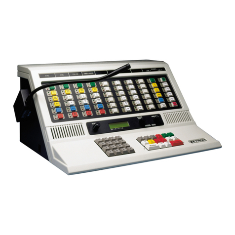
The Model 4018 Desktop Console is a single position console. It contains select and
unselect speakers and their volume controls, channel volume control, 24-hour time display
(or message display), and level meter.
As shown in Figure 7, the field of 16 keys on the lower, right hand side of the Desktop
Console is the system control section. The layout and function of the keys in the system
control section are tailored to your specific system by using the Series 4000 Console
Programming System. See System Control Functions on page 21 for a list of commonly
used system control keys. The functions of these keys usually apply to either the selected
channel or to all channels in general.

Operating Button-Based Consoles
18 025-9535L
Figure 7: Model 4018 Desktop Console
The 16 keys on the lower left hand side are a numeric keypad used for paging.
The field of 60 keys across the upper portion of the Desktop Console is the channel control
section. The layout and function of the keys in the channel control section are also tailored
to your specific system by using the Series 4000 Console Programming System. Usually
the channel legend above a column of keys indicates that those keys are used to control
that channel. See Channel Control Functions on page 26 for a list of commonly used
channel control keys.
Model 4118 Dispatch Console
The Model 4118 Dispatch Console is a single position rackmount console. It contains
select and unselect speakers and their volume controls, channel volume control, 24-hour
time display (or message display), and level meter.
As shown in Figure 8, the field of 16 keys on the right hand side of the console is the
system control section. The layout and function of the keys in the system control section
are tailored to your specific system by using the Series 4000 Console Programming
System. See System Control Functions on page 21 for a list of commonly used system
control keys. The functions of these keys usually apply to either the selected channel or to
all channels in general.
The 16 keys on the left hand side are a numeric keypad used for paging.
The console may be expanded by adding a maximum of three Model 4115 Console
Expanders, which contain a field of 60 programmable, push button switches that are
usually used for system and channel control.
Channel
Control Keys
System
Control Keys
Numeric
Keypad
Audio
Control

19
Console Panel Overview
Figure 8: Model 4118 Dispatch Console
Model 4115 Console Expander
The optional Console Expander (see Figure 9) contains a field of push buttons switches
that are usually used to provide system and channel control buttons for the Model 4118
Dispatch Console.
The layout and function of the system and channel control buttons are tailored to your
specific system. The functions of the system control buttons usually apply to either the
selected channel or to all channels in general. The functions of the channel control buttons
apply only to the designated channel usually indicated by the legend plaque above the
button column.
Figure 9: Model 4115 Console Expander

Operating Button-Based Consoles
20 025-9535L
Console Features
Select/Unselect Speakers
The speaker and volume control on the left are for select audio. The speaker and volume
control on the right are for unselect audio.
Microphone
The Dispatch Console may be equipped with a handset, headset, desktop microphone, or
gooseneck microphone. Lifting the handset from its cradle or plugging the headset into its
jackbox usually causes the Select audio to be routed to the earpiece rather than the Select
speaker. Optionally, a SPEAKER/H-SET button may be used to reroute the audio. The
jackbox has a volume control for the headset earpiece.
The handset and desk top microphone options have a built-in PTT (push to talk) button,
which when pressed, transmits on the Selected channel. Usually, the headset and
gooseneck mount microphone require the use of a foot-operated PTT or the TRANSMIT
button on the console in order to transmit on the Selected channel.
Time/Message Display
The display on the Dispatch Console is normally used to show time in either a 12-hour or
a 24-hour format. The time shown is synchronized with any other consoles in the system.
In systems equipped with the ANI (Automatic Number Identification) option, the display
is also used to show the number of the calling unit. In the event of system changes (such as
a failure), the display may also show diagnostic messages.
If desired, the display can be programmed to show dashes only. For example, when a
facility master clock is used for time reference, this would be appropriate. Refer to the
Series 4000 Communication Control System Installation and Configuration Manual (P/N
025-9533) for programming information.
Level Meter
During transmit and intercom operation, the level meter (under the time display) shows
the level of your voice. During receive operation, the meter shows the level of the audio on
the Selected channel.
This manual suits for next models
3
Table of contents
Other ZETRON Control System manuals
Popular Control System manuals by other brands

AUMA
AUMA SIMA 2 manual

Powrmatic
Powrmatic Vision Maxi Installation & servicing manual

Honeywell
Honeywell LYNX Touch L7000 Series Quick installation guide

hoxter
hoxter ABRA 6.1 Installation and operating instruction

Svarog
Svarog 105 PLASMA CNC operating manual

Woodward
Woodward AtlasSC 8273-040 Installation and operation manual

Woodward
Woodward ECM3 product manual

Pilz
Pilz PNOZ m ES Profinet operating manual

ZH
ZH ZH-EBOX-300 manual

Phason
Phason AutoSort Connect Installation and getting started guide

OBSIDIAN CONTROL SYSTEMS
OBSIDIAN CONTROL SYSTEMS NETRON EN12 installation guide

Mitsubishi Electric
Mitsubishi Electric MELDAS C6 Maintenance manual