manuals.online logo
Brands
  1. Home
  2. •
  3. Brands
  4. •
  5. Teknik
  6. •
  7. Outdoor Cart
  8. •
  9. Teknik Craft 5417047 User manual

Teknik Craft 5417047 User manual

Popular Outdoor Cart manuals by other brands

Costway TH10057 manual

Costway

Costway TH10057 manual

Vivo CART-PC02S instruction manual

Vivo

Vivo CART-PC02S instruction manual

Ergotron STYLEVIEW SV42-3162-1 quick reference

Ergotron

Ergotron STYLEVIEW SV42-3162-1 quick reference

VEVOR SC01 quick start guide

VEVOR

VEVOR SC01 quick start guide

Carts Vermont 20 manual

Carts Vermont

Carts Vermont 20 manual

Vivo CART-PC01 instruction manual

Vivo

Vivo CART-PC01 instruction manual

Costway TL0400 user manual

Costway

Costway TL0400 user manual

XPOtool 30261 user manual

XPOtool

XPOtool 30261 user manual

Branick 130 Installation, Operation & Repair Parts Information

Branick

Branick 130 Installation, Operation & Repair Parts Information

Anthro PrinterCart Assembly instructions

Anthro

Anthro PrinterCart Assembly instructions

Westward 2CZY4 Operating instructions and parts manual

Westward

Westward 2CZY4 Operating instructions and parts manual

Hupfer TTW/V operating instructions

Hupfer

Hupfer TTW/V operating instructions

Gorilla Carts GCR-10P quick start guide

Gorilla Carts

Gorilla Carts GCR-10P quick start guide

Numatic EcoMatic EM-5 Assembly

Numatic

Numatic EcoMatic EM-5 Assembly

Bosch XL-Cart Operating/safety instructions

Bosch

Bosch XL-Cart Operating/safety instructions

Tennsco Modular Cart Top Component Assembly Assembly Instructions/Parts Manual

Tennsco

Tennsco Modular Cart Top Component Assembly Assembly Instructions/Parts Manual

Makita DCU601 instruction manual

Makita

Makita DCU601 instruction manual

Clam POLAR TRAILER HD MAX manual

Clam

Clam POLAR TRAILER HD MAX manual

manuals.online logo
manuals.online logoBrands
  • About & Mission
  • Contact us
  • Privacy Policy
  • Terms and Conditions

Copyright 2025 Manuals.Online. All Rights Reserved.

Craft Cart
Craft Collection | Model 5417047
NOTE: THIS INSTRUCTION
BOOKLET CONTAINS IMPORTANT
SAFETY INFORMATION.
PLEASE READ AND KEEP FOR
FUTURE REFERENCE.
Get your ear a
mobile home.
Teknik
www.teknikoffice.co.uk
Table of Contents Assembly Tools Required
Part Identification
Hardware Identification
Assembly Steps
Français
Español
Safety
Warranty
No. 2 Phillips Screwdriver
Tip Shown Actual Size
Skip the power trip.
This time.
3
4
5-29
30-33
34-37
38
39
Pae 2
Short Screwdriver
Part Identification
åWhile not all parts are labeled, some of the parts will have a label or an inked letter on the ede
to help distinuish similar parts from each other. Use this part identification to help identify similar parts.
Now you know
our ABCs.
A TRAY BOTTOM (1)
B LEFT END (1)
C RIGHT END (1)
D BOTTOM (1)
E BACK (1)
F SHELF (1)
G LOWER BACK RAIL (1)
H UPPER BACK RAIL (2)
J TRAY BACK (1)
K TRAY FRONT (1)
L LEFT TRAY UPRIGHT (1)
M RIGHT TRAY UPRIGHT (1)
N TRAY DIVIDER (1)
O SLIDING TOP (2)
P ADJUSTABLE SHELF FRONT (2)
Q ADJUSTABLE SHELF (2)
R SMALL DRAWER FRONT (1)
S SMALL LEFT DRAWER SIDE (1)
T SMALL RIGHT DRAWER SIDE (1)
U SMALL DRAWER BACK (1)
V LARGE DRAWER FRONT (1)
W LARGE LEFT DRAWER SIDE (1)
X LARGE RIGHT DRAWER SIDE (1)
Y LARGE DRAWER BACK (1)
Z DRAWER BRACE (2)
AA DRAWER BOTTOM (2)
BB ROD CAP (2)
CC ROD (1)
DD BACK DIVIDER (2)
A
B
C
D
E
F
G
H
H
J
K
L
M
N
O
O
P
P
Q
Q
R
S
T
U
V
W
X
Y
Z
Z
AA
AA
DD
CC
BB BB
Pae 3
Hardware Identification
åScrews are shown actual size. You may receive extra hardware with your unit.
CAM SCREW - 35
6
HIDDEN
CAM -35
5WOOD
DOWEL - 40
7
15 SILVER 1-3/16" FLAT HEAD SCREW - 30
SILVER 1/2" FLAT HEAD SCREW - 32
18
SILVER 1/2" PAN HEAD SCREW - 16
17
SMALL SILVER 1/2"
PAN HEAD SCREW - 8
19
METAL PIN - 8
8
(EXTENSION SET SHOWN SEPARATED)
1EXTENSION RAIL - 4 2EXTENSION SLIDE - 4 3LEFT DRAWER SLIDE - 2
4RIGHT DRAWER SLIDE - 2
CLAMP - 4
9LOCKING CASTER - 2
12
CASTER - 2
11
L-WRENCH - 1
13
APPLIQUE CARD - 5
10
WIRE TRAY - 2
14
SILVER 13/16" HEX HEAD SCREW - 2
16
Pae 4
Step 1
å Assemble your unit on a carpeted floor or on the empty
carton to avoid scratchin your unit or the floor.
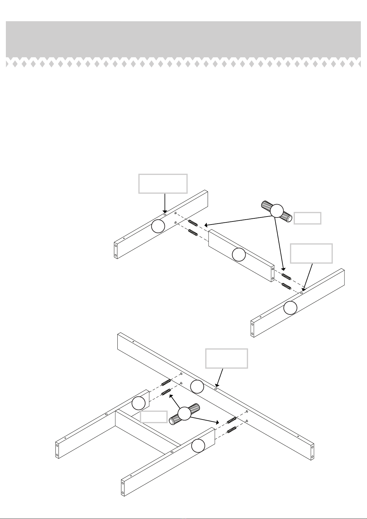
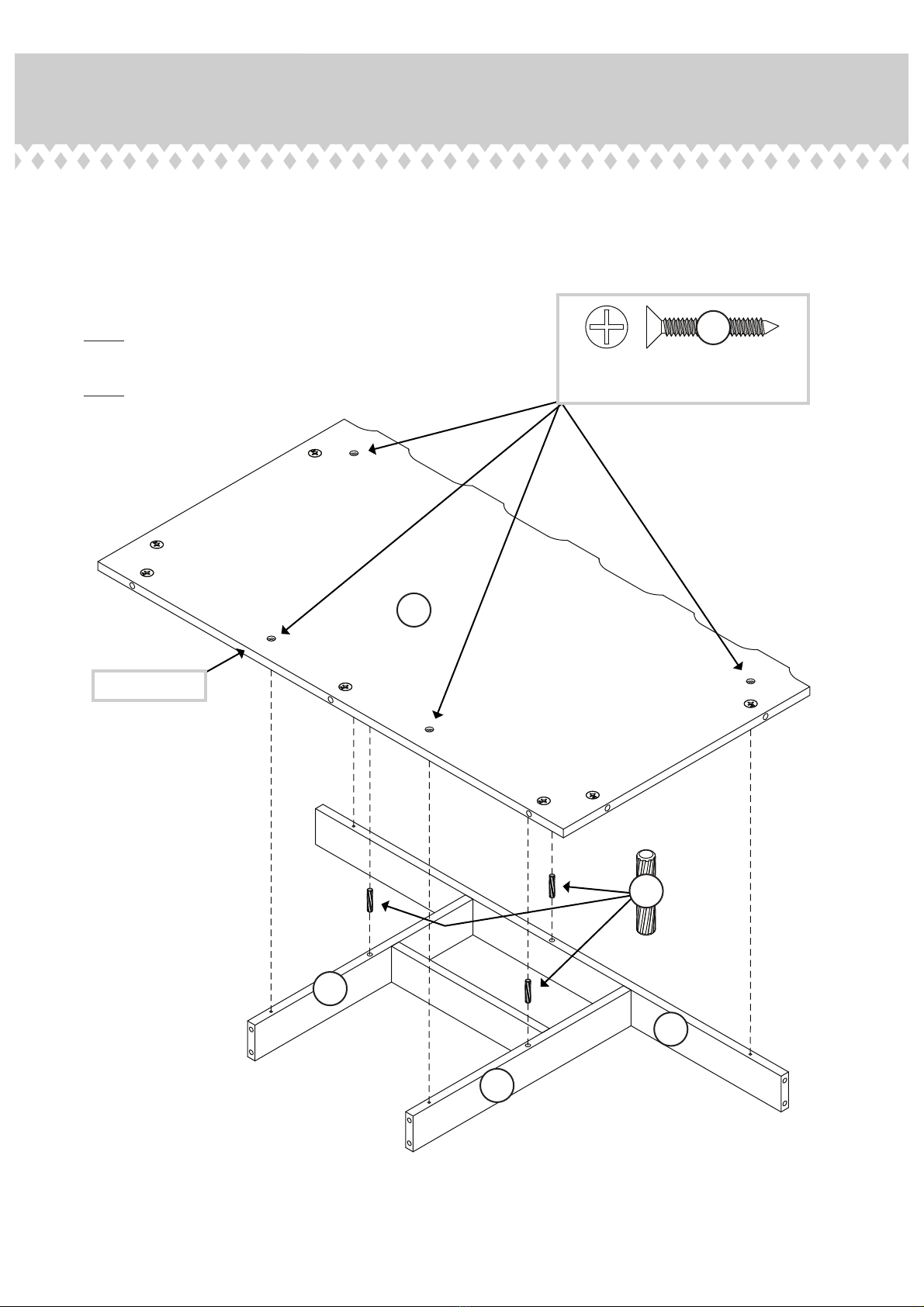
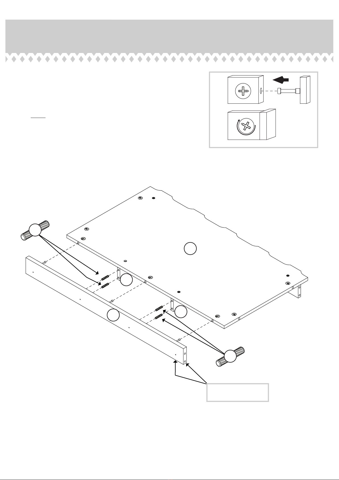
å Push thirty-five HIDDEN CAMS (5) into the TRAY
BOTTOM (A), BACK (E), SHELF (F), UPPER BACK
RAILS (H), ADJUSTABLE SHELVES (Q), DRAWER SIDES
(S, T, W, and X), DRAWER BRACES (Z), and BACK
DIVIDERS (DD).
Arrow
5
Hx 2
Qx 2
Zx 2
DD x 2
Arrow
5
Arrow
The arrow in the HIDDEN
CAM must point toward the
hole in the ede of the board.
Hole
Arrow
5
(35 used)
X
W
T
S
A
E
F
Pae 5
Step 2
6
å Turn thirty-five CAM SCREWS (6) into the ENDS (B and C),
UPPER BACK RAILS (H), TRAY FRONT (K), ADJUSTABLE
SHELF FRONT (P), SMALL DRAWER FRONT (R), and
LARGE DRAWER FRONT (V).
å NOTE: Use the exact holes shown.
P
P
H
H
R
V
C
B
K
Pae 6
(35 used)
å Fasten the LEFT DRAWER SLIDES (3) to the LEFT END (B)
and the RIGHT DRAWER SLIDES (4) to the RIGHT END (C).
Use eiht SILVER 1/2" FLAT HEAD SCREWS (18).
å NOTE: For each DRAWER SLIDE, turn a SCREW into the
hole shown in the enlared diaram. Then, slide the inner
cartride of the DRAWER SLIDE in to find the other hole
that lines up with the hole in the END. Turn a SCREW into
this hole.
å NOTE: The tabs should be oriented as shown.
Step 3
SILVER 1/2" FLAT HEAD SCREW
(8 used for the SLIDES)
18
B
3
4
4
3
C
Use the fourth
hole from the end.
Pae 7www.sauder.com417047
Some assembly
(and snacks) required.
Open end
Open end
tab
tab
å Insert four WOOD DOWELS (7) into the short edes of
the TRAY DIVIDER (N) as shown in the upper diaram.
å Push the TRAY UPRIGHTS (L and M) onto the WOOD
DOWELS in the TRAY DIVIDER.
å Insert four WOOD DOWELS (7) into the short edes of
the TRAY UPRIGHTS (L and M) as shown in the lower
diaram.
å Push the TRAY BACK (J) onto the WOOD DOWELS in the
TRAY UPRIGHTS (L and M).
Step 4
M
L
L
M
N
7
7
The lare hole
must be here.
The lare hole
must be here.
The lare hole
must be here.
J
Pae 8
(4 used)
(4 used)
å Insert three WOOD DOWELS (7) into the top edes of the
TRAY BACK (J) and TRAY UPRIGHTS (L and M).
å Fasten the TRAY BOTTOM (A) to the TRAY BACK (J)
and TRAY UPRIGHTS (L and M). Use four SILVER 1-3/16"
FLAT HEAD SCREWS (15).
å NOTE: Be sure the WOOD DOWELS in the TRAY BACK
and TRAY UPRIGHTS insert into the TRAY BOTTOM.
å NOTE: Start each screw a few turns before tihtenin any
of the them.
Step 5
L
M
7
J
SILVER 1-3/16" FLAT HEAD SCREW
(4 used for the TRAY BOTTOM)
15
Surface with HIDDEN CAMS
Ede with holes
A
Pae 9
å Insert four WOOD DOWELS (7) into the short edes of
the TRAY UPRIGHTS (L and M).
å Fasten the TRAY FRONT (K) to the TRAY BOTTOM (A).
Tihten three HIDDEN CAMS.
å NOTE: Be sure the WOOD DOWELS in the TRAY
UPRIGHTS insert into the holes in the TRAY FRONT.
Step 6
KL
M
1
2
These holes must closer
to the this ede.
7
7
A
Pae 10 www.sauder.com 417047