Teknotel Maestro TSI User manual

2016
Maestro TSI User
Manual

Teknotel Elektronik Ltd. Şti. Mimar Sinan Cad. No: 6 Yenisahra 34746 İstanbul
www.teknotel.com.tr
1
Contents
Contents ............................................................................................................................1
1. INTRODUCTION ...................................................................................................3
2. HOME SCREEN .....................................................................................................3
2.1. First Part of Home Screen......................................................................................3
2.2. Second Part of Home Screen .................................................................................4
2.3. Third Part of Home Screen...............................................................................5
3. MENU......................................................................................................................6
3.1. Signal Plan.............................................................................................................6
3.2. Device Log.............................................................................................................7
3.3. Connection Log......................................................................................................7
3.4. Test.........................................................................................................................9
3.5. Inputs .....................................................................................................................9
3.6. Settings.................................................................................................................11
3.6.1 Date/ Time Setting.........................................................................................11
3.6.2 Menu Language .............................................................................................11
3.6.3 GPS Setting....................................................................................................12
3.6.4 Connection Settings.......................................................................................13
3.6.5 Heater Settings...............................................................................................13
3.6.6 Lamp DIM. Setting........................................................................................14
3.6.7 PSM Calibration ............................................................................................14
3.6.8 User Account Settings (Change Password) ...................................................15
3.6.9 Config Lock...................................................................................................15
3.6.10 External Battery...........................................................................................16
3.6.11 Firmware Upgrade.......................................................................................16


Teknotel Elektronik Ltd. Şti. Mimar Sinan Cad. No: 6 Yenisahra 34746 İstanbul
www.teknotel.com.tr
3
1. INTRODUCTION
In order to provide users with more comprehensive information in a clearer way on the
Maestro device, the existing 4 lines have been replaced with a full colored graphical 320x240x3
dot LCD. The name of the new interface is “Touch Screen Interface - TSI”. TSI communicates
with “Central Processing Module -CPM” while ensuring the interaction between machine and
the user. When maestro cabinet door is opened TSI turns on. TSI sleeps after five minutes if
there is no action. The sleeping function extends the life of display. While TSI is in sleeping
mode it turns on via touching on the screen and goes into home screen.
Figure 1: Touch Screen Interface - TSI
2. HOME SCREEN
2.1. First Part of Home Screen
Figure 2: First part of home screen
Time: It shows, hours, minutes and seconds. (In the format of HHMMSS)
Date: It shows day, month and year. (In the format of DDMMYY)
Sequence: Information of total sequences and operating sequences.
SEQ: It shows total sequence number of the program operating on the device and
also the current running sequence.

Teknotel Elektronik Ltd. Şti. Mimar Sinan Cad. No: 6 Yenisahra 34746 İstanbul
www.teknotel.com.tr
4
DURATION: Total duration of operating sequence and time consumed.
STEP: Total number of step in a running sequence and the current step.
DURATION: Total duration of current step and time consumed.
GPS Status: It shows the status of the GPS. Red color is the state of being passive, and
green color is the state of being active.
Figure 3: GPS Status
GPRS Status: It shows the status of GPRS. If GPRS caption turns red, it means it is not
active. While GPRS being activated, the caption turns into orange and yellow depending on the
connection status. When the connection is secured, the color turns to green.
Figure 4: GPRS Status
Phase: It shows operating phase and the minimum and maximum duration of that phase.
Figure 5: Phase description
Software Version: Display the software version of the CP card.
2.2. Second Part of Home Screen
Figure 6: Second Part of home screen

Teknotel Elektronik Ltd. Şti. Mimar Sinan Cad. No: 6 Yenisahra 34746 İstanbul
www.teknotel.com.tr
5
Vgrid: It shows mains voltage of the device.
Button: It shows the number of pedestrian button.
Loop: It shows the input number of vehicle detector.
Last Usage: It shows the time when the device was used for the last time.
2.3.Third Part of Home Screen
Figure 7: Third Part of Home Screen
Set all groups to red signal: When you press on the red light icon on the left bottom
screen, it cancels all plans that device is operating, and makes all groups to flash in red.
Figure 8: Set all groups to red signal
Set all groups to blank signal: When you press on the no light icon on the central bottom
screen, it cancels all plans that device is operating and makes all groups to dark.
Figure 9: Set all groups to blank signal
Teknotel Elektronik Ltd. Şti. Mimar Sinan Cad. No: 6 Yenisahra 34746 İstanbul
www.teknotel.com.tr
6
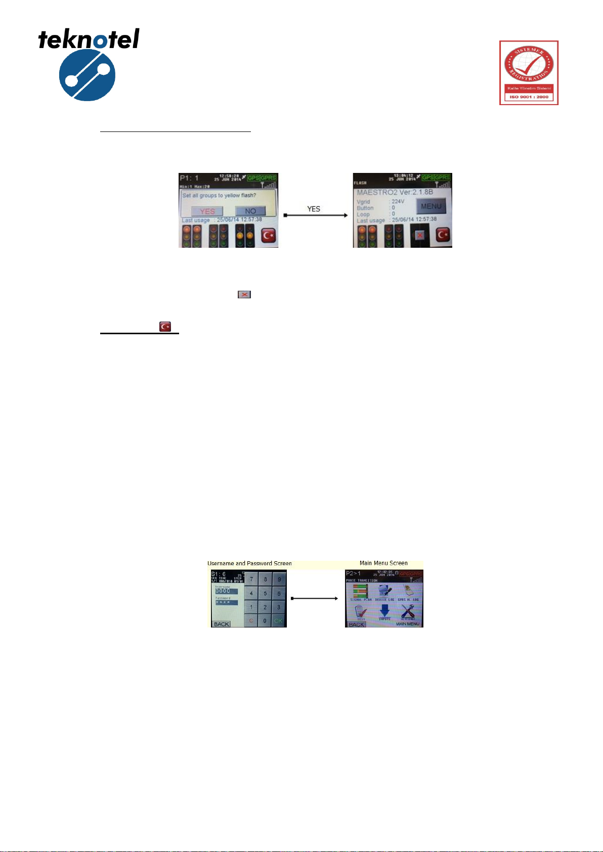
Set all groups to yellow flash: When you press on the yellow light icon on the central
bottom screen, it cancels all plans that device is operating and makes all groups to yellow flash.
Figure 10: Set all groups to yellow flash
In all three cases, press on ( ) sign to return the device back to former status.
Language ( ): It is used to change the language of the device. When the language is
Turkish, the flag of England appears on the screen. If you touch the flag, language changes to
Turkish and a Turkish flag appears on the screen now.
3. MENU
At the home screen, by pressing MENU button the user access to user name and password
screen. On the user name and password screen, 4-digit password and 4-digit username
consisting of a combination of numbers are entered. To go back to home screen, press BACK
button. To delete what you write, press C button. If the username and password are valid,
Pressing OK button will take you to home screen.
Figure 11: Menu
3.1. Signal Plan
It is used for displaying signal plan in the screen. All progressing groups of signal plan
shown in the screen.

Teknotel Elektronik Ltd. Şti. Mimar Sinan Cad. No: 6 Yenisahra 34746 İstanbul
www.teknotel.com.tr
7
Figure 12: Signal Plan
3.2. Device Log
It is used to access to events and malfunction records taking place during the operation of
the device. The records are chronologically ordered. When Log lines are touched on, the
detailed explanation screen of the log opens. Touching the screen again will close this screen.
Figure 13: Device Log
3.3. Connection Log
It shows IMEI number and the connection status of GPRS modem and other devices to
Maestro controller device.
UBLOX MODEM:
"COMMAND MODE" : Commanding on GPRS modem.
"MODEM RESET" : Resetting GPRS modem.
"AT COMMAND" : Sending an "AT" command to the device for checking
the availability.
"ECHO CLOSE" : Closing GPRS Echo command.
"IMEI REQUEST" : Retrieving IMEI number.
"APN SETUP" : Setting up APN.

Teknotel Elektronik Ltd. Şti. Mimar Sinan Cad. No: 6 Yenisahra 34746 İstanbul
www.teknotel.com.tr
8
"DYNAMIC IP ASSIGN." : Assigning a dynamic IP, if it fails, APN is
incorrect.
"GPRS ACTIVATION" : Activating GPRS modem.
"DOMAIN IP REQUEST" : Requesting Domain IP.
"CREATE SOCKET" : Starting TCP (Transmission Control Protocol).
"CONNECT SOCKET" : Central system connecting to created socket
"DIRECT LINK MODE" : GPRS modem is connected to central system.
Figure 14: UBLOX Modem Commands
TELIT MODEM:
"COMMAND MODE" : Commanding on GPRS modem.
"MODEM RESET" : Resetting GPRS modem.
"ECHO CLOSE" : Closing GPRS Echo command.
"IMEI REQUEST" : Retrieving IMEI number.
"APN SETUP" : Setting up APN.
"GPRS ACTIVATION" : Activating GPRS modem.
"CONNECT SOCKET" : Creating socket and central system connecting
to created socket.
Figure 15: TELIT Modem Commands
Teknotel Elektronik Ltd. Şti. Mimar Sinan Cad. No: 6 Yenisahra 34746 İstanbul
www.teknotel.com.tr
9
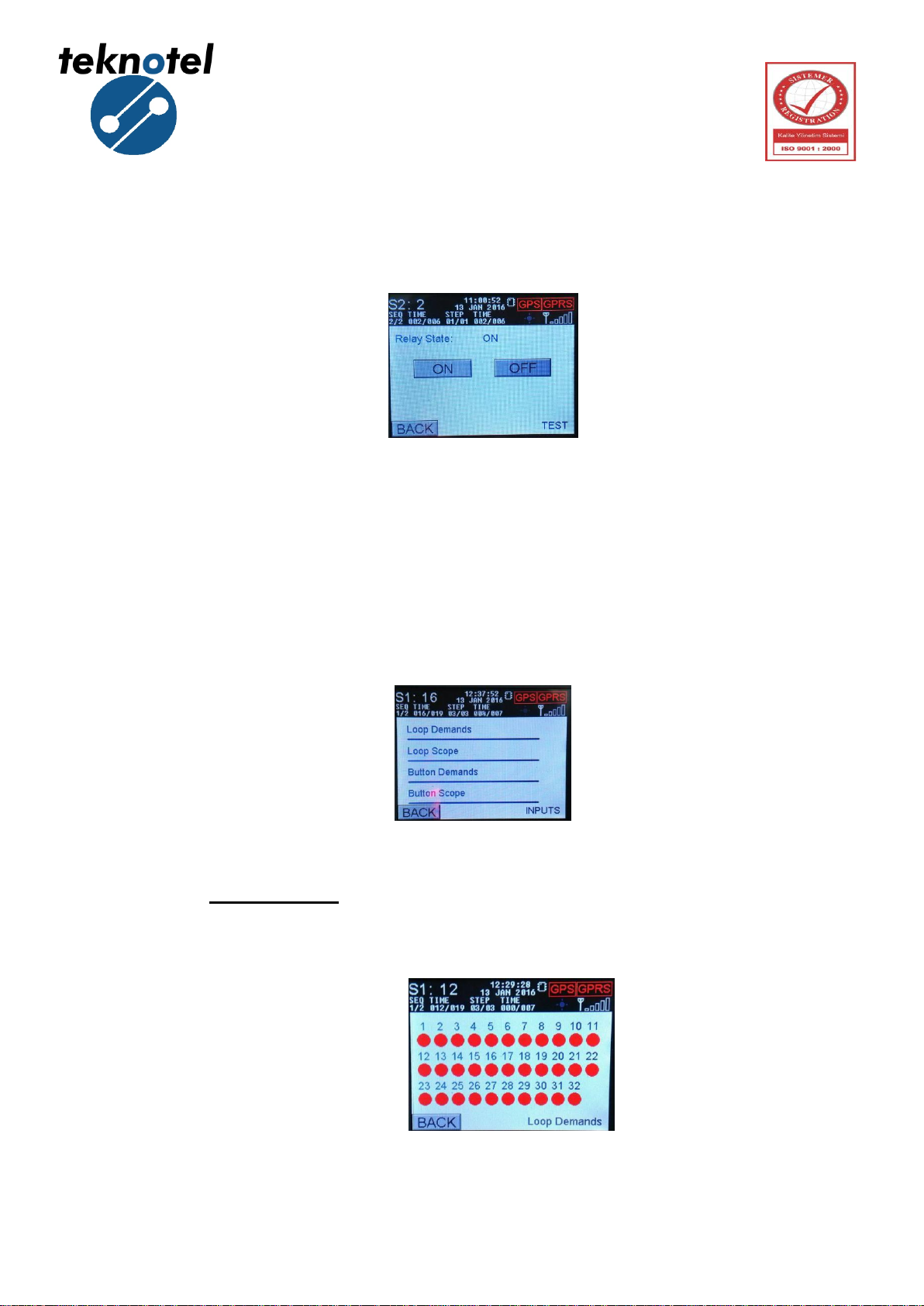
3.4. Test
It is used to change the status of relay. The user may choose ON or OFF.
Figure 16: Relay State
3.5. Inputs
It shows the requests from pedestrian button and detectors. There are two types of input
on the inputs screen; Loop and Button. The request from any type of input can be monitored as
shown below:
Figure 17: Inputs Screen
Loop Demands: It is used to observe the requests coming from loop entries.
According to the request coming from loop detector, the color of the number of
related entry changes.
Figure 18: Loop Demands Screen

Teknotel Elektronik Ltd. Şti. Mimar Sinan Cad. No: 6 Yenisahra 34746 İstanbul
www.teknotel.com.tr
10
Loop Scope: The requests coming from the loop detectors could be seen on the
loop scope (Loop Tracking) screen depending on the time.
Figure 19: Loop Scope Screen
Button Demands: It is used to monitor the requests coming from the pedestrian buttons
on the field. According to the requests, the colour of related entry changes.
Figure 20: Button Demands Screen
Button Scope: The request coming from pedestrian buttons can be monitored on
buttons scope (Button Tracking) screen depending on the time.
Figure 21: Button Scope Screen
Teknotel Elektronik Ltd. Şti. Mimar Sinan Cad. No: 6 Yenisahra 34746 İstanbul
www.teknotel.com.tr
11
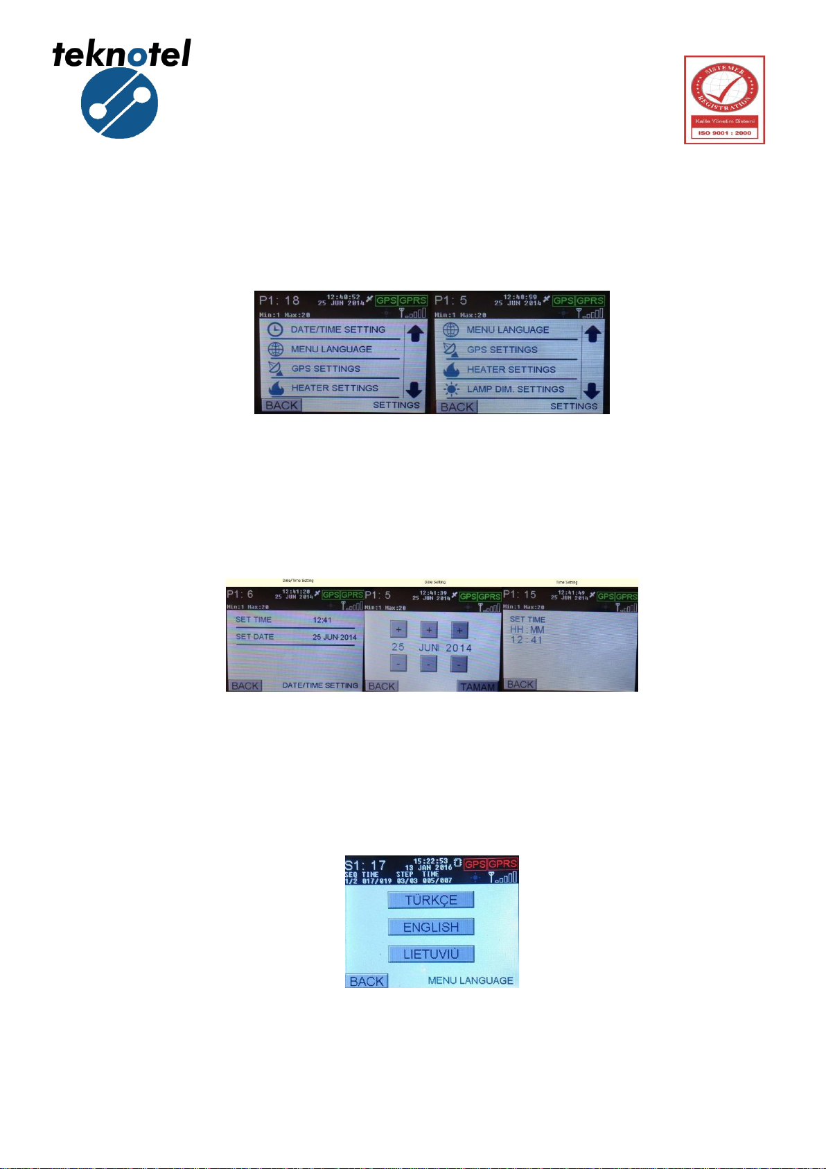
3.6. Settings
By pressing SETTINGS icon on home screen, you can go to settings screen. On this
screen, the user can make following changes:
Figure 22: Settings Screen
3.6.1 Date/ Time Setting
In this menu, date and clock settings can be edited.
Figure 23: Date and Time Settings Screen
3.6.2 Menu Language
In this menu language can be selected as Turkish, English or Lithuanian.
Figure 24: Menu Language Screen
Teknotel Elektronik Ltd. Şti. Mimar Sinan Cad. No: 6 Yenisahra 34746 İstanbul
www.teknotel.com.tr
12
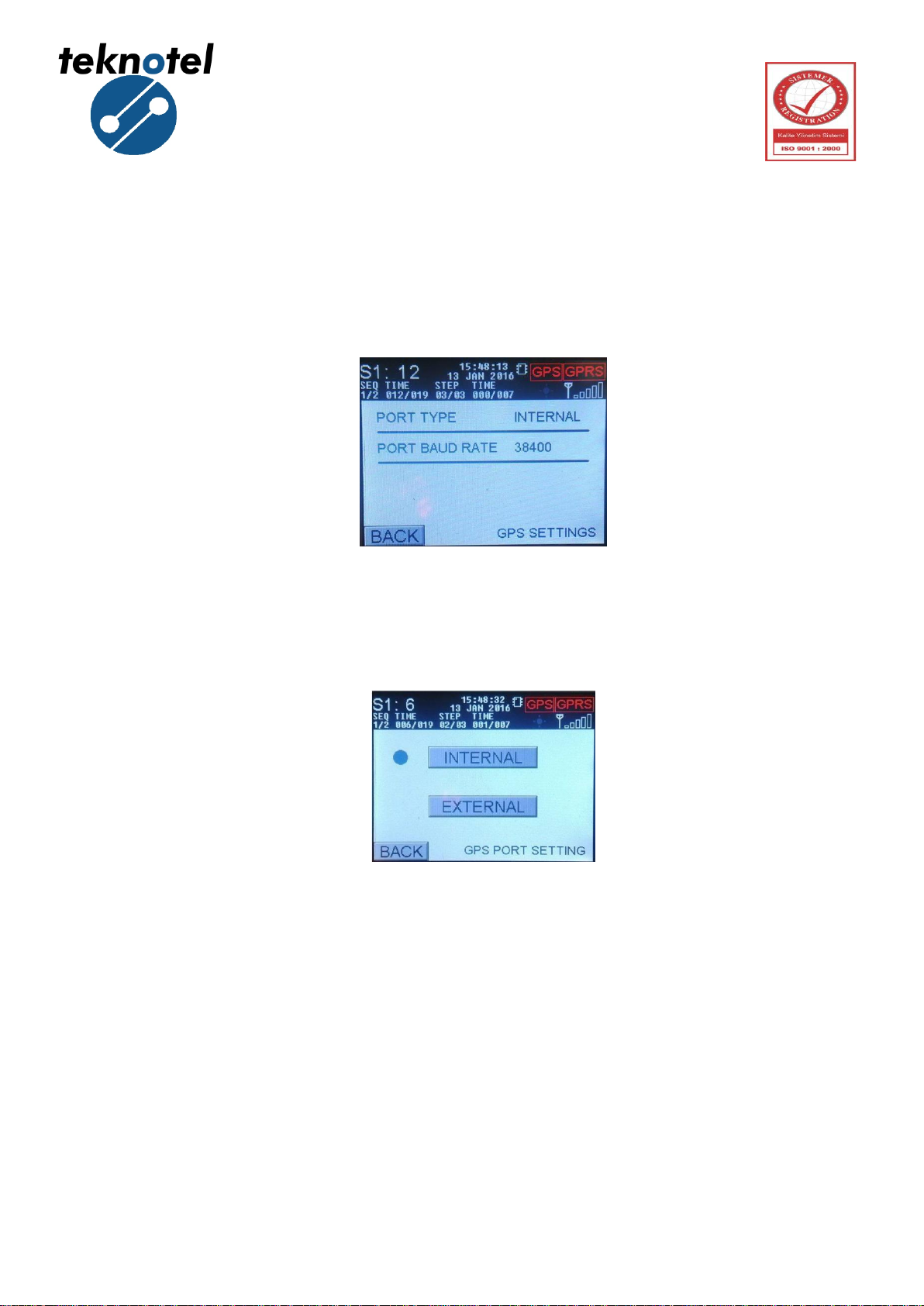
3.6.3 GPS Setting
Maestro intersection controller device may use the RMC messages that come from GPS
for updating clock/date. Maestro capable of reading message sent 2400, 4800, 9600, 19200,
28800, 38400, 57600, 76800 and 115200 baud rate.
Figure 25: GPS Setting Screen
In this menu user should select port type, maestro intersection controller includes two
type of GPS module:
Figure 26: GPS Type Selection Screen
After selecting type of GPS module, the device restart itself. Else, the device returns the
settings menu.

Teknotel Elektronik Ltd. Şti. Mimar Sinan Cad. No: 6 Yenisahra 34746 İstanbul
www.teknotel.com.tr
13
By clicking port baud rate, user can select the baud rate of GPS module.
Figure 27: Baud Rate Selection Screen
3.6.4 Connection Settings
Maestro intersection controller in order to connect with MCTS web user interface use
GPRS module or Ethernet. In this menu connection type can be selected by user.
Figure 28: Connection Type Selection Screen
3.6.5 Heater Settings
Heater setting is active for maestro software version 2.1.8 or under. For versions above
2.1.8 heater setting is not active.
Figure 29: Heater Settings Screen

Teknotel Elektronik Ltd. Şti. Mimar Sinan Cad. No: 6 Yenisahra 34746 İstanbul
www.teknotel.com.tr
14
3.6.6 Lamp DIM. Setting
Lamp DIM. Setting is active for maestro software version 2.1.8 or under. For versions
above 2.1.8 lamp DIM. Setting is not active.
Figure 30: Lamp DIM. Settings Screen
3.6.7 PSM Calibration
If there is a difference between measured mains voltage and the value on the screen, a
calibration to PSM module is necessary. Measured mains voltage is on the top line and
calibrated value appears on the bottom line.
Figure 31: PSM Calibration Screen

Teknotel Elektronik Ltd. Şti. Mimar Sinan Cad. No: 6 Yenisahra 34746 İstanbul
www.teknotel.com.tr
15
3.6.8 User Account Settings (Change Password)
In this menu user can change the password.
Figure 32: User Account Screen
Enter four digit new password and click OK.
Figure 33: User Account Screen
3.6.9 Config Lock
In this menu user can change the configuration status of Maestro intersection controller.
The status can be changed to “Enable” and “locked”. When the status is enable controller can
be programed using Maestro Config Tool program.
Figure 34: Configuration Status Screen

Teknotel Elektronik Ltd. Şti. Mimar Sinan Cad. No: 6 Yenisahra 34746 İstanbul
www.teknotel.com.tr
16
3.6.10 External Battery
In this menu user can change the External Battery status of Maestro intersection
controller. The status can be changed to “Active” and “Disabled”.
Figure 35: External Battery Usage Screen
3.6.11 Firmware Upgrade
In this menu user can change the state of IAP mode in Maestro Controller device.
Figure 36: Firmware Upgrade Screen
3.6.12 Default Settings (Return Factory Settings)
In this menu, the device’s EEPROM is cleaned completely and return to factory settings
configuration. All programs, including saved signal programs and signal plans are deleted.
Device is restarted and intersection controller outputs are disabled. (No signal is sent to signal
outputs).

Teknotel Elektronik Ltd. Şti. Mimar Sinan Cad. No: 6 Yenisahra 34746 İstanbul
www.teknotel.com.tr
17
Figure 37: Return Factory Settings Screen
Table of contents

 instruction manual")


