teko Astra-Z-8845 User manual

Astra-Z-8845 Ver. B
Wireless Repeater / Router
Operation Manual
Revision 8845-bv1_5_en
This operation manual is intended for studying the operating
principles, proper use, storage, and maintenance of the
Wireless Repeater/Router Astra-Z-8845 version B
(hereinafter referred to as router) (Figure 1).
The manufacturer reserves the right to make alteration regarding
refinement of the product without prior notification. All
improvements are included in new revision of the operation
manual.
List of Abbreviations:
Astra-Zitadel System: Astra-Zitadel on-site Wireless Intrusion
/ Fire Detection and Alarming System;
Astra-Zitadel System Control Panel: Astra-Z-812M, Astra-Z-
8945 ver.A, Astra-8945 Pro, Astra-712 Pro or Astra-812 Pro
Control Panel (with connected WE-2.4 Wireless Extender);
AL: Alarm Loop;
LT: Astra-942 Laser Tester;
FW: Firmware;
MSS Astra-Z: Astra-Z Monitoring Software Suite;
MSS Astra Pro: Astra Pro Monitoring Software Suite;
1 Function
1.1 The router is designed for operation
within the Astra-Zitadel system.
1.2 The router is intended:
- for retransmitting messages (notifications,
control commands, responses, handshakes,
etc.) from wireless devices within the Astra-
Zitadel system through all retransmission
levels to the control panel;
- for automatically routing messages from
wireless devices if the current data transfer route is lost;
- for controlling external devices (sirens, lighted signs) via its
outputs.
1.3 The router ensures operation directly with 30 detectors
(plus two mobile devices).
1.4 The router ensures TM identifier code transmitting to
control panel via radio.
1.5 The router ensures control of passive detectors and other
devices with «dry contact»-type outputs through the Zone-
GND input with current control.
1.6 Power is supplied to the router from an external
redundant 10-27 V power supply unit (e.g. Astra-712/0).
2 Specification
Technical Parameters of Radio Channel
Operating frequency range, MHz .....................2 400 to 2 483, 5
Number of operating channels at 5 MHz intervals...................16
Channel width, MHz ..................................................................2
Wireless coverage range, line-of-sight, m, min....................1000
AL Technical Parameters
Zone-GND terminal voltage
in standby mode, V.......................................................2,7 to 5,0
Zone-GND terminal
active ripple voltage, mV, max.................................................50
AL resistance*, kΩ, in status:
- «Normal»,..................................................................3,0 to 5,0
- «Violation»............................................................<3,0 or >5,0
Relay Output Technical Parameters
- Relay 1:
Loading voltage, V, max........................................................100
Loading current, mA, max .....................................................150
- Relay 2:
Loading voltage, V, max........................................................250
Loading current, A, max ............................................................5
General technical parameters
Power supply voltage, V.................................................10 to 27
Current consumption
(at power supply voltage 10 V), mA, max:
- in transmitting mode, relay opened, registered
in wireless network ................................................................122
- in transmitting mode, relay closed, registered
in wireless network ................................................................160
Technical readiness time, s, max.............................................20
Overall dimensions, mm, max ...................................1016332
Weight, kg, max....................................................................0,07
Operating Conditions
Temperature range, °C.................................. from -30 up to +50
Relative air humidity, %....................................up to 95 at 35 °C
without condensation of moisture
__________________________________
* The permissible parameter spread for resistance is not more than 10%.
3 Delivery Set
Astra-Z-8845 version B........................................................1pcs
Screw 2.9×25......................................................................4 pcs
Dowel 5х25.........................................................................4 pcs
Operation Manual.............................................................1 copy
4 Structure
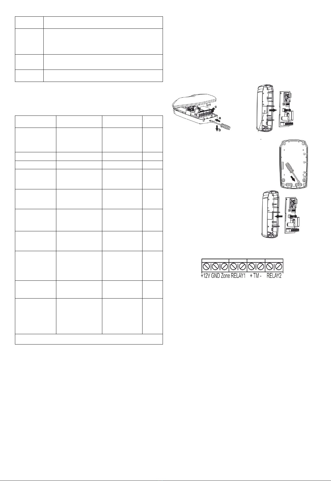
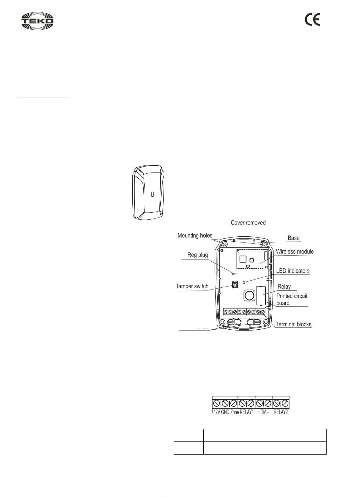
4.1 Structurally the router is designed as a block consisting of a
base and removable cover. Mounted inside the block is a printed
circuit board (PCB) with radio elements (Figure 2).
Figure 2
4.2 Mounted on PCB are red and white LEDs for router’s
functional status and the wireless network status supervision
respectively.
4.3 Mounted on PCB is a tamper switch, which results in the
«Tampering» notification when the cover is removed.
4.4 Mounted on PCB is a terminal block. For terminal function
see Table 1.
Table 1: Terminals
Terminal
Name
Terminal function and characteristics
+12V,
GND
Input for power supply connection
Figure 1
Wire
Insertion
hole

Revision 8845-bv1_5_en
2
Terminal
Name
Terminal function and characteristics
GND,
Zone
AL Input with current control for external devices
with «dry contact»outputs connecting.
Wire length must be not greater than 10 m.
RELAY1
RELAY2
Outputs for slave devices connecting
+ТМ -
TM reader connection input
5 Notification types
Table 2: Notifications processed by LEDs and Control Panel (or
MSS interface)
Notification
Type
Red
LED
White
LED
Control
Panel
Standby
mode start
Lights up one
time for 1 to 20
seconds after
powering up
Not lit
-
Normal
Not lit
Not lit
+
AL normal
Not lit
Not lit
+
Violation
Lights up one
time for 0.2
seconds
Not lit
+
AL recovery
Lights up one
time for 0.2
seconds
Not lit
-
Main power
supply failure
Triple blink
every 25
seconds
Not lit
+
Tampering/
Tamper
recovery
Lights up one
time for 0.2
seconds
Not lit
+
Network
search
Not lit
Blinks with
frequency of 5
Hz for 1 to 60
seconds
-
No network
Not lit
Double blink
every 25
seconds
-
Command
received from
LT
Lights up one
time for 2
seconds upon
receipt of
command from
any LT button
-
-
+: notification issued; –: notification not issued
6 Operating Modes
6.1 The router operating modes are defined via radio upon a
command from the control panel in accordance with an
appropriate Astra-Zitadel Quick Start Guide* or MSS
interface**:
1) switching AL supervision ON/OFF;
2) switching TM input (from MSS Astra-Pro only);
3) setting RELAY1 and RELAY2 output operating modes;
4) FW upgrade.
6.2 Operating modes initiated by the Astra-942 laser tester
buttons:
1) test (upper button);
2) wireless network optimization (middle button);
3) router registration in wireless network (lower button).
7 Pre-starting procedure
7.1 After transportation in conditions differing from those of
operation, the router must be kept unpacked for 4 hours in the
expected operating conditions.
7.2 Running Router
Step-1
Push the cover catch out
of the base groove.
Remove the cover.
Step-2
Unbend the latch on the base.
Remove PCB.
Step-3
Push the blank out of the wire insertion hole
in the base.
Lead the wires from the power supply unit
through the hole.
Step-4
Reinstall PCB.
Step-5
Connect wires to the terminals in accordance with Table 1.
Supply power from an external source.
7.3 Registering the Router in the Wireless Network
Router registration is required for router identification in the
wireless network in which it is supposed to operate.
Step-1 According to Astra-Zitadel System Control Panel`s
Operating Manual * perform the following procedure:
1) Install Software ** (MSS Astra-Z, Pconf-Z or MSS Astra
Pro) intended for configuring Control Panel.
2) Create wireless network
Step-2 Perform p.7.2.
Step-3
Switch the control panel to Wireless component
registration mode by the method described in an appropriate
Astra-Zitadel system operation manual* or Quick Start
Guide*.
The mode switches for 60 s.
Latch

Revision 8845-bv1_5_en
3
Step-4
The router can be registered by one of 2 methods:
a) by command from the LT (step 5);
b) using the Reg plug and the tamper switch (step 6).
WARNING!
Avoid initiating registration procedure on several
detectors simultaneously.
Step-5
Initiating Router Registration Procedure Using LT (can
be conducted with router assembled):
1) Press the lower button on the LT and hold until a beam
appears.
2) Direct the laser beam at the router and irradiate LED for
at least 1 second.
The router’s red LED lights up for 2 seconds, and then the
white LED blinks with a frequency of 5 Hz for not more
than 60 seconds («Network search»).
Step-6
Initiating Router Registration
Procedure Using the Reg Plug and
Tamper Switch:
1) Shortly (for 0.5-2.5 seconds)
close the Reg plug with a screwdriver.
The router switches to registration in
wireless network mode for 60
seconds.
2) Within 60 seconds, shortly press the tamper switch on
the router. The router switches to wireless network search
mode, at that white LED blinks at a frequency of 5 Hz.
Step-7
Verify registration by the control panel indication:
If registration procedure
completed successfully, the
abbreviated name of router
«RTR»appears on the screen or
«RTRxxx registered» notification
appears on the control panel`s
screen.
Assemble the router.
If registration procedure failed, the control panel screen
displays «Registration time expired»notification. In this
case, repeat the registration procedure, i.e. execute steps 3
and 5 or 3 and 6.
Step-8
Attention!
Do not switch off the router before the end of
registration and setting of all wireless devices in the
system.
After successful registration of the router, for long term
storage before its installation, it is allowed to switch the
router OFF.
When power is supplied, there is no need to re-register the
router in the same wireless network if it was not intentionally
removed from the network through Astra-Z-812M control panel.
7.4 Deleting Router from Wireless Network
Deletion the router from wireless network is performed
using Software ** or through Control Panel`s menu.
When deleting detector from wireless network, Control Panel
transmits notification about deletion to detector within two
periods of RF supervision time. After receiving the
notification detector issues "No network" notification.
To speed up the deletion procedure:
- remove detector`s cover
- shortly close Reg plug
- press and hold down tamper switch for 8-10 sec.
The router issues "No network" notification to LED and is
available for registration.
8 Installation
8.1 Installation Procedure
Step-1
Push the cover catch out of
the base groove. Remove
the cover.
Step-2
Unbend back the latch on the
base. Remove PCB.
Step-3
Push the blank out of the wire insertion
and mounting holes in the base.
Lead the wires from the power supply
unit and AL through the hole.
Step-4
Mark the selected
installation site for the
applied base.
Fasten the detector base.
Step-5
Reinstall PCB.
Step-6
Carry out wiring to the
router terminals in
accordance with Table 1.
Step-7
Replace the router cover
(press until it clicks).
Step-8
Set the router input and output operating modes from the
control panel (or MSS interface) in accordance with an
appropriate Astra-Zitadel system Quick Start Guide*.
Step-9
Verify Router Operability:
1) Verify the router status on the control panel or MSS
(«Normal» status should appear);
2) Initiate a test mode in accordance with an appropriate
Astra-Zitadel system Quick Start Guide*.
Latch
Mounting holes

Revision 8845-bv1_5_en
4
8.2 To ensure the alarm system reliable operation, testing
and maintenance of the router is recommended as follows:
- Inspect the integrity and secure fastening of the router
housing, external wires status and reliability of connection at
least once a month;
- Verify router operability by the method described in p.8.1 step
9at least once a month;
- Clean contaminants from the router at least once in three
months.
9 Labeling
The following information is marked on the label attached to the router
housing:
- manufacturer trademark;
- abbreviated router designation;
- firmware version;
- month and year of manufacture;
- conformity mark (if an appropriate certificate is available)
- bar-code that duplicates textual information.
10 EC conformity declarations
This product is in conformity with the provisions of:
R&TTE Directive 1999/5/EC, Article 10.5;
EN 60950: 2001 Safety of information technology equipment;
EN 50371 Generic standard to demonstrate the compliance of low-
power electronic and electrical apparatuses with the basic restrictions
related to human exposure to electromagnetic fields (10 MHz - 300
GHz) –General public;
EN 301489-17 V1.1.1 (09-2000) Electromagnetic Compatibility and
radio spectrum Matters (ERM); Electromagnetic Compatibility (EMC)
standard for radio equipment and services; Part 17: Specific condi-
tions for wideband data Hiperlan equipment;
EN 300220-1 V1.3.1 (2000-09) Electromagnetic compatibility and
Radio spectrum Matters (ERM); Short range devices; Technical char-
acteristics and test methods for radio equipment to be used in the 25
MHz to 1 000 MHz frequency range with power levels ranging up to
500 mW; Part 1: Parameters intended for regulatory purposes.
Construction of the detector provides for protection class IP41.
11 Recycling
The router poses no threat to human life, health or to the environment;
after its service life is over, it can be recycled without any special
environmental protection measures.
12 Warranty terms
12.1 Quality Management System meets provisions of ISO 9001-2011.
12.2 The manufacturer guarantees the compliance of the router to
specifications on condition that user observes required conditions of
transportation, storage, installation and operation.
12.3 The storage warranty period is 5 years and 6 months from the
date of manufacture.
12.4 The operating warranty period is 5 years from the startup date,
but not more than 5 years and 6 months from the date of manufacture.
12.5 The manufacturer guarantees replacement or repair of the
product during the warranty period.
12.6 The warranty doesn’t come into effect in the following cases:
-not adherence to the operating manual;
-mechanical damage to the router;
-repair of the router by any third-party service except the
Manufacturer.
12.7 The warranty applies to the router only. All equipment from other
manufacturers used in conjunction with the router is subject to its own
warranty terms.
The manufacturer bears no responsibility for death, injury,
property damage or other incidental or premeditated loss based
on user's statement that the device failed to implement its
functions.
* Available for free downloading from www.controlex.eu
and/or integrated with configuring software.
** Available for free downloading from www.controlex.eu.
Sales:
Controlex GmbH
Warranty service and
technical support:
ТЕКО, LLC
Philosophenweg 31-33
47051 Duisburg, Germany
Phone: +49 (0) 203 / 393 91 188
Fax: +49 (0) 203 / 393 91 189
GSM: +49 (0) 178 / 218 48 22
E-mail: info@controlex.eu
Web: www.controlex.eu
Prospekt Pobedy str. 19
420138 Kazan, Russia
Phone: +7 (843) 261-55-75
Fax: +7 (843) 261-58-08
E-mail: info@teko.biz
support@teko.biz
Web: www.teko.biz
Made in Russia
Other teko Repeater manuals
Popular Repeater manuals by other brands

Arris
Arris Touchstone WR2100 Quick installation guide

Omikron
Omikron CallHelp 500RP manual

Aztech
Aztech WL580E Easy start guide

Arrista Technologies
Arrista Technologies SignalReach CR500 Installation & user manual

Ltech
Ltech 2310200 quick start guide

BWI Eagle
BWI Eagle AIR-EAGLE SR PLUS 36-4500 Product information bulletin

Vision
Vision ZR1202EU Installation & operation manual

Thuraya
Thuraya ThurayaSingle user guide

Wurth Elektronik
Wurth Elektronik ANR001 manual

SMC Networks
SMC Networks SMCWEB-N2 user guide

Lutron Electronics
Lutron Electronics RadioRA RA-REP installation instructions

Motorola
Motorola h13tty3110a Supplement to instruction manual