ENDEAVOUR ET2404 User manual

1
ET2404
6000 COUNT DIGITAL AUTOMOTIVE
MULTIMETER WITH SQUARE WAVE GENERATOR
INSTRUCTION MANUAL
This instrument is a compact 6000 count digital automotive engine analyser
multimeter, with a unique square wave generator. This tool is designed for the
professional mechanic.
Key functions include AC / DC Voltage, AC / DC Current, Resistance,
Capacitance, Frequency, Duty cycle, Temperature, Diode / Continuity testing,
Tachometer, Dwell, ms-PULSE,Analog Frequency / Duty / Voltage / Resistance
Signal Output.
The square wave can be generated from 1 – 12V DC | 10% - 90% duty cycle |
20Hz – 3,000Hz. This output is easily adjusted from the buttons on the face of
the tool, and using the dual banana jacks marked “output”.
Safety Warnings
DANGER
Engines produce carbon monoxide which is odorless, causes slower reaction
time, and can lead to serious injury.When the engine is operating keep
service areas WELL VENTILATED or attach the vehicle exhaust system to the
shop exhaust removal system.
Set the parking brake and block the wheels before testing or repairing any
vehicle. It is especially important to block the wheels on front-wheel drive
vehicles. The parking brake does not hold the drive wheels.
Wear an eye shield when testing or repairing vehicles. Exceeding the limits of
this meter is dangerous and can expose you to serious or possibly fatal injury.
Read this manual carefully before use and be careful to understand the specific
safety limits of this meter.
•Voltage between this unit & ground must not exceed 1000V DC / 750V AC.
•Use caution when measuring voltage above 25VAC / DC.
•Circuits being tested must be protected by a 20Afuse or circuit breaker.

2
•Do not use this meter if it has been damaged
•Do not use test leads if insulation is damaged and / or wiring is exposed.
•Use current clamps to measure circuits exceeding 20A.
•Avoid electrical shock: do not touch probe tips.
•Do not measure voltage with the test leads in the 20A or mA terminals.
•When testing for the presence of voltage or current, make sure the meter is
functioning correctly. Take a reading of a known voltage or current before
accepting a zero reading.
•Choose the proper range and function for the measurement. Do not attempt
voltage or current measurements that may exceed the ratings marked on the
function / range switch or terminal.
•When measuring current, connect the meter in series with the load.
•Never connect more than one set of test leads to the meter.
•Disconnect the live test lead before disconnecting the common test lead.
•The mA and the 20A terminals are protected by fuses. To avoid possible
injury or damage, use only in circuits limited to 600mA or 20A continuous for
15 seconds.
IMPORTANT
•To maintain accuracy of the meter, replace the battery immediately when the
battery symbol appears on the meter display.
•Avoid measuring errors from outside interference: keep the meter away from
spark plugs or coil wires.
•Avoid damaging the meter when testing voltage: disconnect the test leads
from the test points before changing functions.
•Do not exceed the limits shown in the table below:
•
Function
Terminal
Input Limit
AC Volts
V/Ω/RPM
750V AC rms
DC Volts
1000V DC
Frequency / Duty
V/Ω/RPM 250V AC/DC
Resistance / Diode
AC / DC 600mA
600mA
600mAAC / DC
Clamp Current
600mV AC / DC
AC / DC 20A
20A
20AAC / DC
RPM, ms-PULSE
V/Ω/RPM 250V AC / DC
Cap, Temperature
Voltage Output
Over 1k
Ω
Resistance Output
±5V

3
•20Ameasurement continuous for 30 seconds maximum.
•Ohm cannot be measured if voltage is present. Ohms can only be
measured in a non-powered circuit. However, the meter is protected to 250V.
SPECIFICATIONS
GENERAL SPECIFICATIONS
Display: 6000 digits LCD with 20mm high numerals
Auto Functions: Auto-zero, Auto-polarity, Auto-range
Auto power off: 15 minutes after stopping usage, the meter will enter Power
off mode. Pushing switch to OFF position will disable Auto Power off.
Low Battery Indication: " ".
Over Range Indication: "OL".
Power Supply: 9V battery (NEDA 1604or IEC 6F22)
Reading Rate Time: 3 readings / sec (approx)
Maximum Common Mode Voltage: 500V AC / DC peak.
Safety Standards: The meter conforms with IEC1010 Double Insulation,
Pollution degree 2, Overvoltage CategoryⅡ.
Operating Environment: 0℃to 50℃(32℉to 122℉) at ≤70% relative
humidity.
Storage Environment: -20℃to 60℃(-4℉to 140℉) at ≤80% relative
humidity .
Temperature Coefficient: 0.1×(specified accuracy) /℃(≤18℃or≥28℃)
Fuse: 0.8A / 250V, 5×20mm fast acting, 20A /250V, 6×30mm fast acting.
Dimensions: 218mm×122mm×75mm
Weight: 760g (including battery and holster)
Electrical Specifications
Accuracy is given as ±([% of reading]+[ number of leads significant digits]) at
18℃to 28℃(65℉to 83℉), with relative humidity up to 70%.
RPM (tach)
Range: 60 - 8999 RPM
Resolution: 1 RPM
Effect reading: >60RPM
Accuracy:±(2.5%rdg+10dgt)
Overload protection: 250V DC or RMSAC
Pulse width
Range: 0.1ms-10.0ms
Accuracy: ±(2.5%+0.2ms)
Overload protection: 250V DC or RMSAC

4
% Duty cycle
Range: 1.0-99.0%
Resolution: 0.1%
Pulse width: >100us,<100ms
Accuracy:±(2.5%rdg+10dgt)
Overload protection: 250V DC or RMSAC
Temperature
Range:-50 to 1100℃,-50 to 2000℉
Resolution: 1℃/1℉
Accuracy: -50 to 1100℃±(2%rdg+2℃)
-50 to 2000℉±(2%rdg+4℉)
Sensor: Type K thermocouple
Input protection: 250V DC or RMS AC
DC Voltage (auto ranging)
Range: 600mV
Accuracy:± (2.5%rdg+15dgt)
Range: 6V, 60V, 600V, 1000V
Accuracy:± (0.8%rdg+8dgt)
Resolution: Minimum 100uV
Input impedance: >10MΩ
Overload protection: 1000V DC or 750V AC rms
AC Voltage True RMS (auto ranging)
Range: 600mV, 6V, 60V, 600V, 750V
Resolution: 100uV
Accuracy: 400mV ,750V± (3.0%rdg+15dgt) at 50Hz to 100Hz
,4V,40V,400V, ± (1.5%rdg+15dgt) at 50Hz to 1kHz
Input impedance: >10MΩ
Overload protection: 1000V DC or 750V AC rms
AC / DC Current
Range: 60mA, 600mA, 20A.
Resolution: 10 uA
Accuracy:
DCA: 60mA,600mA ±(1.5%rdg+10dgt)
ACA: 60mA,600mA ±(1.8%rdg+15dgt)
DCA: 20A ±(2.0%rdg+15dgt)

5
ACA: 20A ±(2.5%rdg+15dgt)
Input protection: 0.8A/250V fuse on 600mArange
20A / 250V high energy fuse on 20Arange
AC / DC Current Test with Current Clamp Adaptor
Range: 6A, 40A, 600A.
Resolution: Minimum 1mA
ACA Test Frequency response: 50Hz to 400Hz
Accuracy:
6A/40A ±(3.0%rdg+15dgtt)
600A ±(3.5%rdg+10dgt)
Input protection: 250V DC or 250V AC rms
Resistance (auto ranging)
Range: 600Ω, 6KΩ, 60KΩ, 600KΩ, 6MΩ, 60MΩ
Accuracy:±(1.5%rdg+15dgts) on 600Ωrange
±(1.0%rdg+10dgts) on 6kΩto 600kΩranges
±(3.5%rdg+15dgts) on 6MΩto 60MΩranges
Open circuit voltage: 0.4V DC
Overload protection: 250V DC or RMSAC.
Frequency (auto ranging)
Ranges: 9.999kHz, 99.99kHz, 999.9kHz, 9.999MHz
Resolution: 0.001Hz
Accuracy: ±(0.1%rdg+5dgts)
Sensitivity: 1V
Overload protection: 250V DC or RMSAC
Capacitance (auto ranging)
Ranges: 9.999nF, 99.99nF, 999.9nF, 9.999uF, 99.99uF, 999.9uF, 9.999mF,
99.99mF.
Resolution: 1pF
Accuracy:±(3.0%rdg+20dgts) on 9.999nF range
±(2.5%rdg+10dgts) on 99.99nF to 9.999uF ranges
±(3.0%rdg+25dgts) on 99.99uF to999.9uF ranges
±(10%rdg+15dgts) on 9.999mF to99.99mF ranges
Overload protection: 250V DC or RMSAC
Diode Test

6
Test condition: Forward DC current approx. 1.5mA
Reversed DC voltage approx. 1.5V
Overload protection: 250V DC or RMSAC.
Audible Continuity
Open circuit voltage: 0.4Vdc
≤50ΩBuzzer sounds
Overload protection: 250V DC or RMSAC.
Signal Analog Output (Analog Frequency / Duty / DC and AC Voltage /
Resistance Signal Output)
% Duty cycle: 10%-90%
DC Voltage: 0-1V、0-5V、0-12V(±1%)
AC Voltage: 0-1V、0-5V、0-12V(±1.5%)
Resistance: 5KΩRange:200Ω-2KΩ(±3.5%±0.1 KΩ)
2KΩ-5KΩ(±3.5%±0.2 KΩ)
200KΩRange: 4KΩ-200KΩ(±3.5%±0.5 KΩ)
“︽” “︾”Buttons quickly adjust output signal value
“∧” “∨” Buttons fine adjust output signal value
Standard Accessories
1 Test lead 2 pcs
2
Crocodile clip
4 pcs
3 Instruction manual 1 pce
4
Soft set
1 pce
5 Colour box 1 pce
6 Temperature probe 1 pce
7
Battery (9V)
1 pce
Optional Accessories
1
RPM Inductive pick up probe
2 Current clamp
3 Test leads

7
Getting Started
This chapter will help you get started.
It describes the basic functions of the meter.
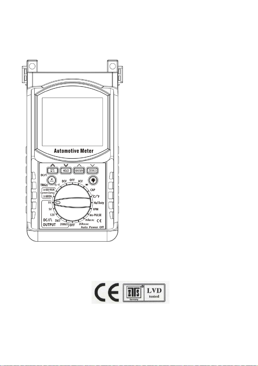
Front Panel
①AC/DC & and °C/°F switch
②Hold switch
③MAX / MIN switch
④ZERO switch
⑤Backlight switch
⑥RANGE & STROKE 4/2(DIS) & DC OUTPUT / Square wave output
⑦Function / Range dial: Select a function or turn the meter OFF.
⑧Safety protector
Selecting Functions
Turn the rotary switch in either direction to select a function.
The range is automatically selected by the meter. But you can also select a
range within a function by pressing the range button. Always select a range
higher than you expect the measurement to be. Then select a lower range if
better accuracy is needed.
•If the range is too high, then reading are less accurate.
•If the range is too low, the meter will show OL (over limit).

8
Push Button Functions
DC/AC Button
Press this button to select the following functions:
AC/DC Voltage & Current Diode/Continuity °C/°F.
RANGE & Stroke 4/2(DIS) ms TRIGGER ±
DC OUTPUT/ Square wave output BUTTON
Press this button to select:
RPM x 10 RPM position
STROKE 4 2 DIS
ms-Pulse
TRIGGER ±
Signal Ouput
DC Output / Square Wave Output
V/A Resistance Position
Manual Range
Manual Ranging
The meter turns on by default in the autorange mode. Press the Range button
to change to manual ranging. The icon " " will appear. Each press of the
range button will step to the next range as indicated by the units and decimal
point location. Press and hold the Range button for two secondsto return to
autoranging.
NOTE:
•If the range is too high, then readings are less accurate.
•If the range is too low, the meter will show OL (over limit).
Data Hold
The Data Hold feature stores the last reading in memory.
•Press the HOLD button once to hold the present reading.
•Press the HOLD button again to exit and resume readings.
Always select a range higher than you expect the measurement to be. Then
select a lower range if better accuracy is needed.
•If the range is too high, then reading are less accurate.
•If the range is too low, the meter will show OL (over limit).
9
Min / Max Button
Press the MAX/MIN button to activate the MAX/MIN recording mode. The
display icon "MAX or MIN" will appear. The meter will change to manual ranging
& display and hold the maximum or minimum reading and will update only when
a new “max or min” occurs.
Press the MAX/MIN key and a blinking “MAX MIN” will appear. The meter will
display the present reading, but will continue to update and store the max and
min readings.
To exit MAX/MIN mode press and hold the MAX/MIN key for 2 seconds.
Zero Button
When testing small capacitance(≤9.999nF), to ensure measurement accuracy,
first press "ZERO", before taking any measurements.
Push the key, the present display value will be stored in memory, then the new
display value is the difference between input value and stored data
Backlight Button
Press the BACKLIGHT button to turn the backlight ON. Press the
BACKLIGHT button again to turn the backlight OFF.
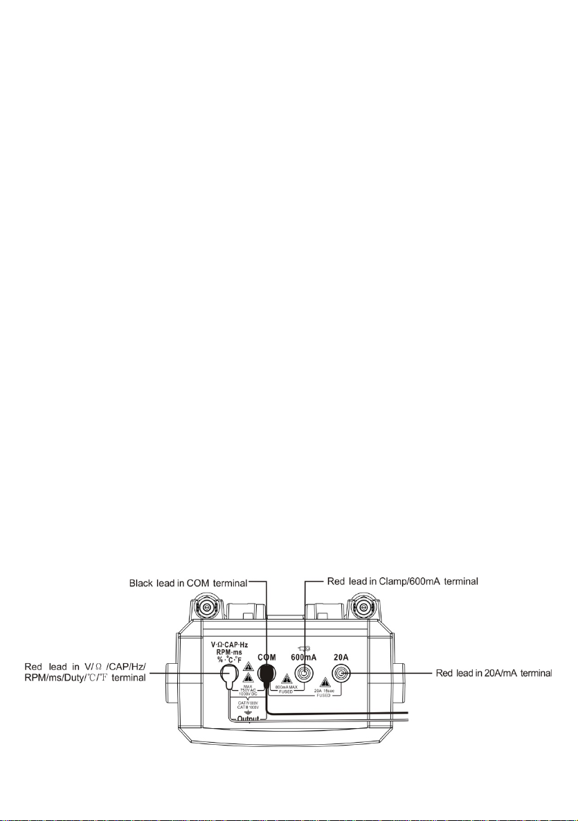
Connection Diagram
1.Black lead in COM terminal

1
Red lead in V/Ω/CAP/Hz/RPM/ms/Duty/℃/℉terminal
2.Black lead in COM terminal | Red lead in Clamp / 600mA terminal
3.Black lead in COM terminal | Red lead in 20A / mA terminal
Fuse Maintenance and Battery Replacement
WARNING:
Avoid electrical shock; remove test leads before opening the case.
Do not operate the meter or rotate the meter switch when the case is open.
1. To replace a battery or fuse, loosen the four screws in the back of the case
and remove the case by lifting up and forward. Replace the battery with a 9V
alkaline battery.
2. To replace the fuse, firmly grasp the printed circuit board by the edges and lift
up and out of the case.
IMPORTANT:
To prevent contamination of the circuitry, your hands must be clean and the
printed circuit board must be held by its edges.
·Replace the fuse with the same type of fuse.
◎10A is a F10A, 250V high energy, fast acting fuse.
◎mA is a F500mA, 250V high energy, fast acting fuse.
·Mark sure the replacement fuse is centered in the fuse holder.
Carefully re-insert the PC board into the case. Re-assemble the case, then
fasten the four screws.
Troubleshooting
1.Meter will not turn ON.
·Check the battery contacts for a tight fit.
·Check for a minimum battery voltage of 8.0 Volts.
·Make sure the battery wires are not pinched in the case.
2.Ampere reading is erratic or there is no reading at all.
·Disassemble the meter back cover and test the fuses for continuity.
3. Meter reading is erratic.
·Printed circuit board contaminated from handling with hands.
·Low battery.
·Open circuit in a test lead (frayed or broken wire).
·Wrong range selected.
·For frequencies below 1Hz, the display will show 00.00Hz.

1
·“Blown” fuse.
4. Meter reading does not change.
·“ Hold”feature is still toggled ON.

AUTOMOTIVE MULTIMETER
INSTRUCTION MANUAL
This manual suits for next models
1
Table of contents
Other ENDEAVOUR Multimeter manuals

Popular Multimeter manuals by other brands

Unit
Unit UT71C operating manual

YATO
YATO YT-73084 operating manual

Extech Instruments
Extech Instruments 382100 user manual

Faithfull
Faithfull FAI DETMULTI instruction manual

3B SCIENTIFIC PHYSICS
3B SCIENTIFIC PHYSICS Escola 30 instruction sheet

Elenco Electronics
Elenco Electronics M-2625 Operator's instruction manual


